Product / JCC
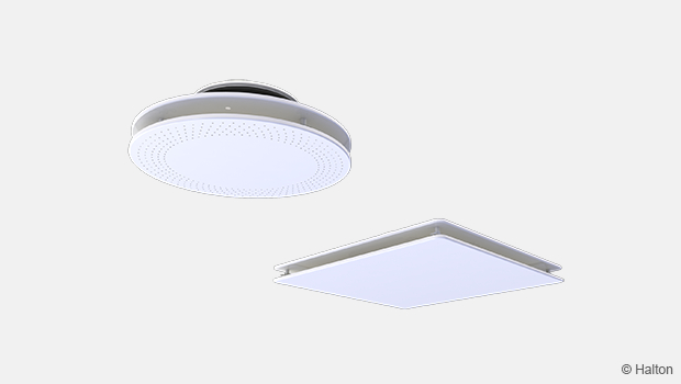
Halton Jaz JCC – Diffuser
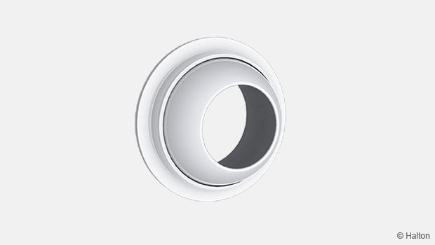
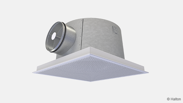
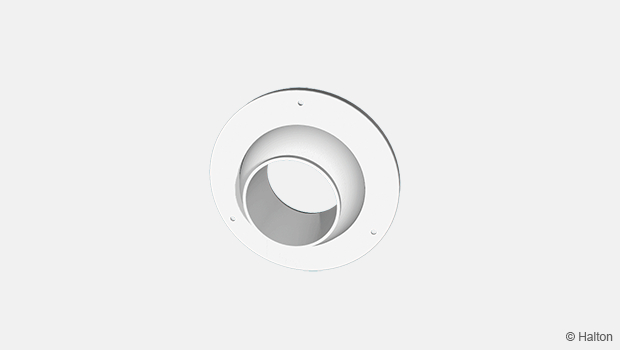
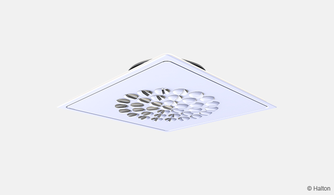
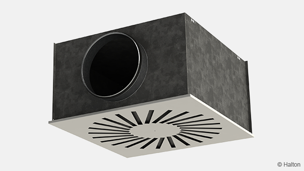
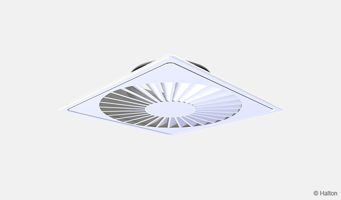
This Halton Jaz diffuser is ideal for renovated buildings and cabins due to the low construction size of the product. It is also available in stainless steel which gives the product an esthetical outlook, perforated options also available.
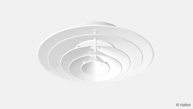
- Ceiling diffuser with side slot in square and circular shape
- Deflector panels available for selection of flow pattern in 1-4 directions
Link to Revit object (MagiCAD Cloud)
Overview
Features
- Ceiling diffuser with side slot in square and circular shape
- Low construction height minimizes the installation space
- Diffuser is available for air supply and exhaust
- Installation either directly to ductwork or to balancing plenum
- Detachable front panel enables the cleaning of the diffuser and ductwork
- Deflector panels available for selection of flow pattern in 1-4 directions
Accessories
- Deflector panel to provide control for flow pattern direction
- Balancing plenum with measurement and adjustment functions
- Installation panel for modular ceiling
- Control knob when in use with cabin units (ships and ferries)
Product models
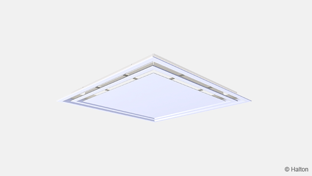
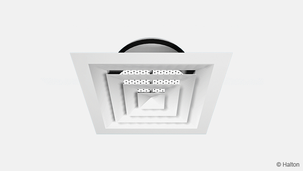
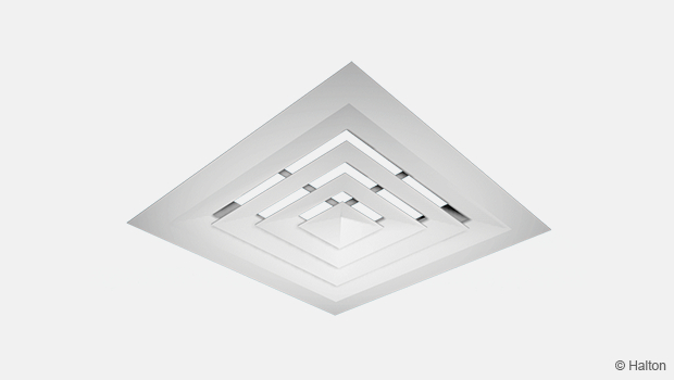
- Square, with solid or perforated front panel
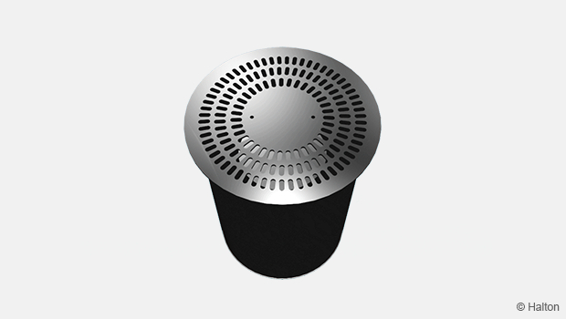
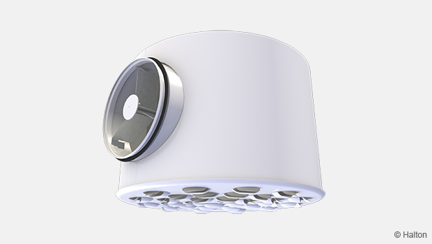
- Circular, with solid or perforated front panel
- Direct installation to the standard T-bar ceiling opening
- Material alternative in stainless steel (EN1.4404/AISI316L)
Operating principle

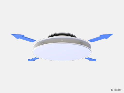
Air is supplied into the space through the side slots and mixed with the room air outside the diffuser.
Recommended maximum air temperature difference between supply and room air is 10 °C.
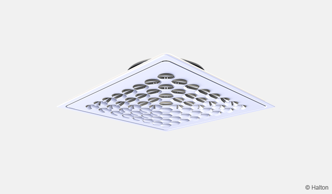
The throw pattern can be deflected in different (1, 2 and 3) directions with the deflection parts (included in delivery).
Deflection part not needed for 4 direction supply or exhaust airflow .
Features and options
| Accessory | Code | Description |
| Deflector part | DP | A set of parts for providing the flow pattern in 3, 2 and 1 directions (not needed for 4 direction flow). See Fig.1. |
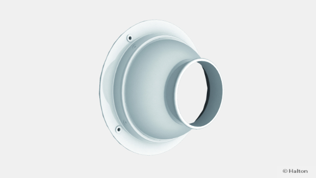
| Balancing plenum | PDI | For balancing and equalising the airflow and attenuating the duct noise |
| Installation panel | PI-N | For standard 600×600 module ceiling installation, colour white (RAL 9003). See Fig.2. and 3. |
| Control knob | CK | For controlling cabin unit (ships and ferries). See Fig.4. |
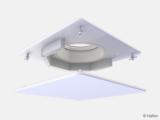
Fig.1. Deflector part attached to diffuser (DP)
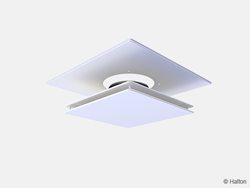
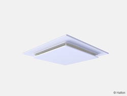
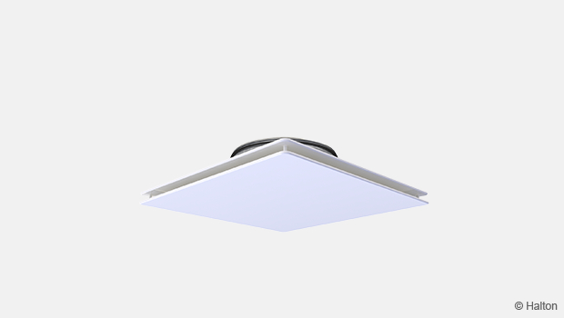
Fig.2. Square diffuser with installation panel (PI)
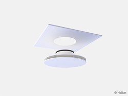
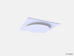
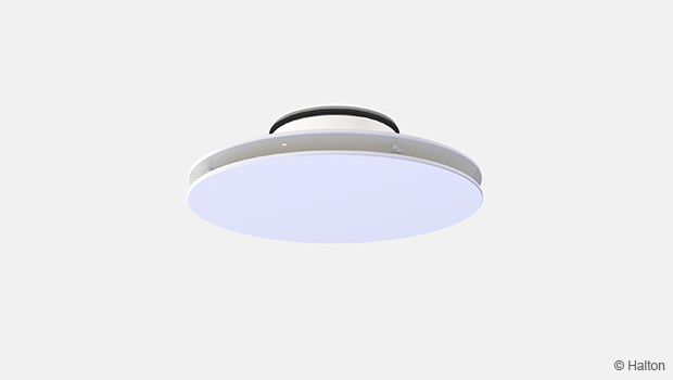
Fig.3. Circular diffuser with installation panel (PI)
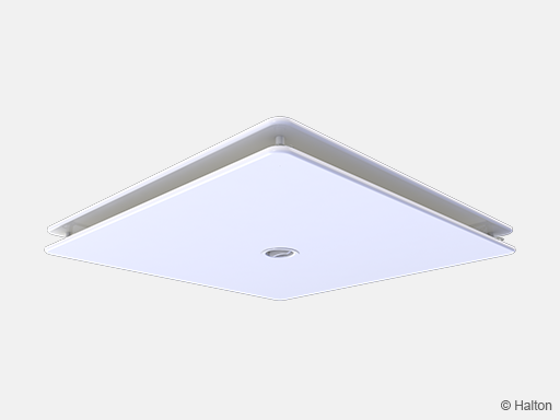
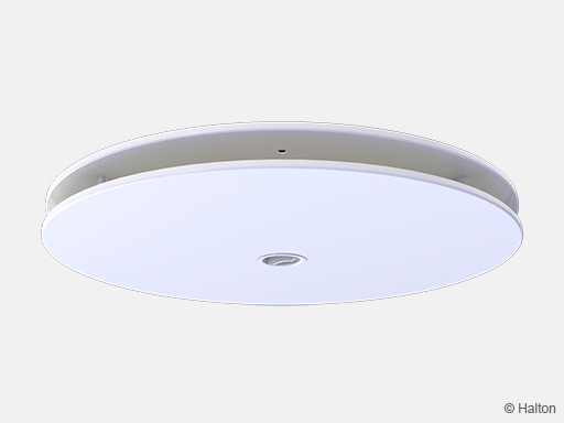
Fig.4. Diffuser with control knob (CK)
Quick selection
Values with adjustment module (MSM) fully open.
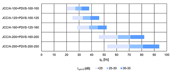
Fig. 5. Quick selection for square front panel (models A and C), supply with unit l/s

Fig. 6. Quick selection for circular front panel (models B and D), supply with unit l/s
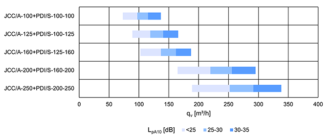
Fig. 7. Quick selection for square front panel (models A and C), supply with unit m3/h
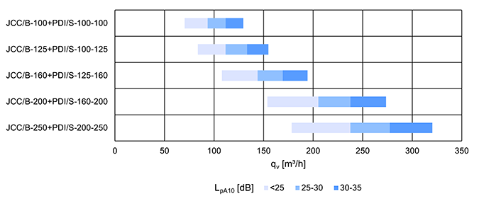
Fig. 8. Quick selection for circular front panel (models B and D), supply with unit m3/h
Stucture and materials
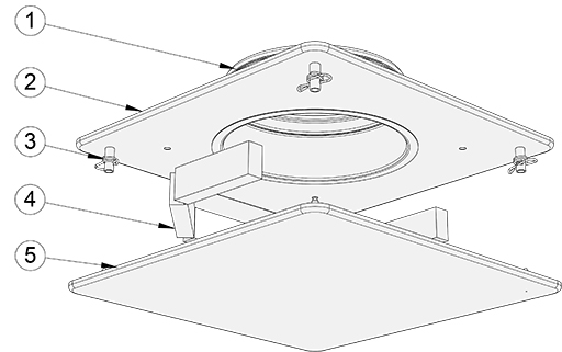
| Key | Part | Material | Note |
| 1 | Duct seal gasket | Rubber | – |
| 2 | Upper plate | Steel or stainless steel (EN1.4404/AISI 316L) |
Powder paint, white (RAL 9003) Special colours available on request |
| 3 | Spring lock | Steel or stainless steel (EN1.4404/AISI 316L) |
– |
| 4 | Deflector part | Foamed plastic | – |
| 5 | Front panel | Steel or stainless steel (EN1.4404/AISI 316L) |
Powder paint, white (RAL 9003) Special colours available on request |
Note: Same material options available for circular and square models.
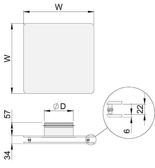
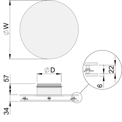
Dimensions and weight
Halton Jaz JCC, square model (A,C)
Halton Jaz JCC, circular model (B,D)
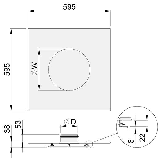
Halton Jaz JCC, square ceiling integrated model (WS)
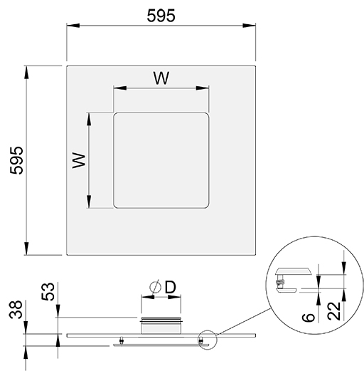
Halton Jaz JCC, circular ceiling integrated model (WS)
| NS | W [mm] |
ØD [mm] |
Weight, square [kg] |
Weight, circular [kg] |
Weight, square + WS [kg] |
Weight, circular +WS [kg] |
| 100 | 300 | 99 | 1.4 | 1.2 | 3.6 | 3.4 |
| 125 | 300 | 124 | 1.4 | 1.2 | 3.6 | 3.4 |
| 160 | 300 | 159 | 1.4 | 1.2 | 3.6 | 3.4 |
| 200 | 450 | 199 | 2.9 | 2.3 | 4.9 | 4.4 |
| 250 | 450 | 249 | 2.8 | 2.3 | 4.9 | 4.4 |
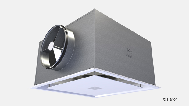
Halton Jaz JCC with Halton Pop PDI plenum
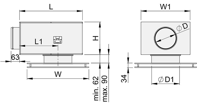
Fig. 9. Halton Jaz JCC with Halton Pop PDI plenum, externally positioned connection spigot
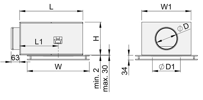
Fig. 10. Halton Jaz JCC with Halton Pop PDI plenum, internally positioned connection spigot
| JCC | W [mm] |
PDI | ØD [mm] |
ØD1 [mm] |
L [mm] |
W1 [mm] |
H [mm] |
L1 [mm] |
Weight, square [kg] |
Weight, circular [kg] |
| 100 | 300 | 100-100 | 99 | 102 | 308 | 282 | 172 | 168 | 4.1 | 3.9 |
| 125 | 300 | 100-125 | 99 | 127 | 308 | 282 | 172 | 168 | 4.1 | 3.9 |
| 300 | 125-125 | 124 | 127 | 308 | 282 | 172 | 168 | 4.2 | 4.0 | |
| 160 | 300 | 125-160 | 124 | 162 | 308 | 282 | 172 | 168 | 4.1 | 3.9 |
| 300 | 160-160 | 159 | 162 | 458 | 358 | 239 | 280 | 6.4 | 6.2 | |
| 200 | 450 | 160-200 | 159 | 202 | 458 | 358 | 239 | 280 | 7.8 | 7.2 |
| 450 | 200-200 | 199 | 202 | 458 | 358 | 239 | 280 | 7.9 | 7.3 | |
| 250 | 450 | 200-250 | 199 | 252 | 458 | 358 | 239 | 280 | 7.7 | 7.2 |
| 450 | 250-250 | 249 | 252 | 520 | 480 | 359 | 280 | 11.0 | 10.5 |
Product models
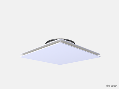
Fig.11. Halton Jaz JCC, square with solid front panel (A)
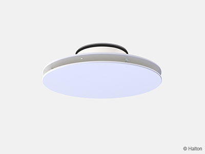
Fig.12. Halton Jaz JCC, circular with solid front panel (B)
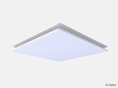
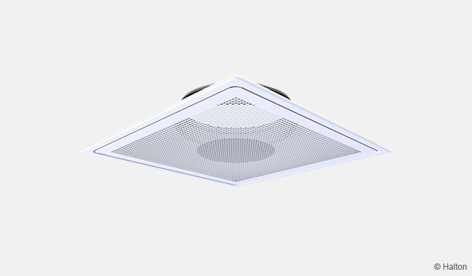
Fig.13. Halton Jaz JCC, square with perforated front panel (C)
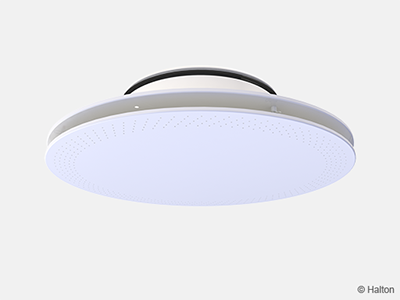
Fig.14. Halton Jaz JCC, circular with perforated front panel (D)
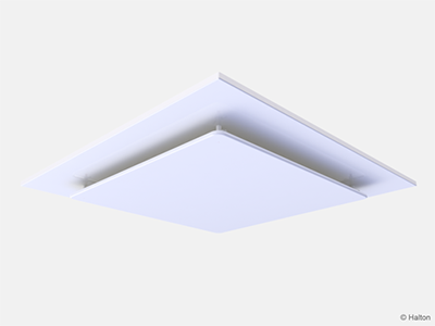
Fig.15. Halton Jaz JCC, square solid ceiling integrated model (WS=T)
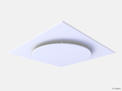
Fig.16. Halton Jaz JCC, circular solid ceiling integrated model (WS=T)
Specification
The diffuser is made of painted steel with a white (RAL 9003) standard colour or stainless steel (EN1.4404/AISI 316L). Air is introduced into the space through the side slot, ensuring a high mixing rate. The flow pattern of the diffuser is as standard for 4 directions. It is adjustable in 1, 2, or 3 -way directions by shaping the deflector.
Alternative 1: Without balancing plenum
The diffuser has a spigot with integral gasket for connection to circular duct.
The diffuser has a detachable solid or perforated front panel to provide access to the duct.
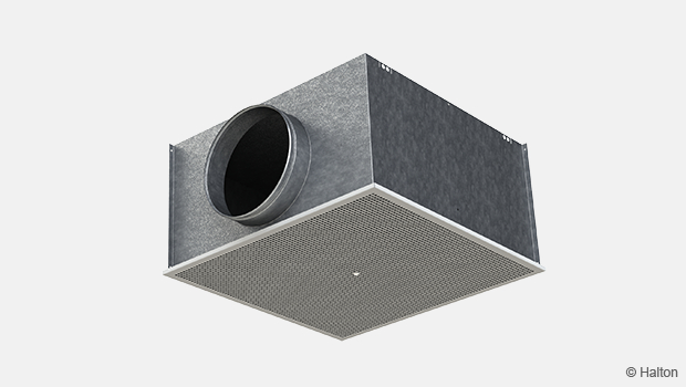
Alternative 2: With balancing plenum
The diffuser is connected to a balancing plenum equipped with a measurement and adjustment module.
The diffuser has a detachable solid or perforated front panel to provide access to the measurement and adjustment module in the plenum.
The balancing plenum has a spigot with integral gasket for airtight duct connection.
The balancing plenum comprises sound attenuation material made of polyester fibre with a washable surface or mineral wool.
Installation
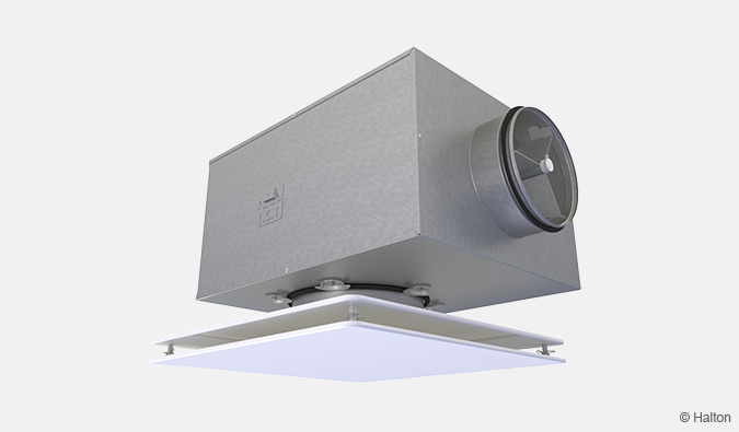
Fig. 17. Halton Jaz JCC diffuser with square front panel connected to a Halton Pop PDI plenum
The diffuser is connected usually to balancing plenum Halton Pop PDI. Alternatively, it can be connected direct to the duct by riveting or screwing. In that case, minimum safety distance to the next T-branch or curve is three times the duct diameter (3xD).
The desired flow pattern is selected during installation with the deflector parts, according to the installation manual. In exhaust application the deflector part is not used.
Commissioning
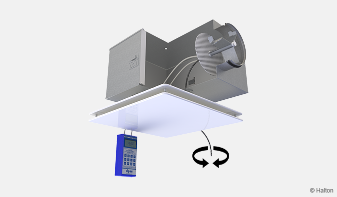
Fig. 18. Adjustment of airflow of diffuser and plenum combination
Airflow control
The diffuser itself has no airflow adjustment. To adjust and measure the supply airflow rate, the diffuser shall be combined with Halton Pop PDI balancing plenum with measurement and adjustment module MSM. In case of exhaust air, use of adjustment module MEM is recommended. It is not possible to measure exhaust airflow rate with adjustment module MEM.
Open the front plate and pass the tubes and control spindle through the front panel (Fig. 18.). Replace the front panel. Measure the differential pressure with a manometer. The flow rate is calculated using the formula below:
![]()
where
- qv Airflow rate [l/s] or [m3/h]
- ∆pm Measured pressure [Pa]
- k The k factor (see the table below)
Adjust the airflow rate by rotating the control spindle until the desired airflow rate (pressure difference) is achieved.
Set the tubes and spindle back into the plenum. Damper position can be locked with a knurled head screw of the adjuster.
| Duct connection (PDI) | k factor of MSM adjuster, opening >0 [l/s] | |
| > 8D | Min. 3D | |
| 100 | 5.7 | 7.5 |
| 125 | 9.6 | 12.6 |
| 160 | 16.4 | 21.9 |
| 200 | 26.3 | 31.0 |
| 250 | 47.1 | 51.5 |
| 315 | 78.8 | – |
| Duct connection (PDI) | k factor of MSM adjuster, opening >0 [m3/h] | |
| > 8D | Min. 3D | |
| 100 | 20.6 | 27.0 |
| 125 | 34.4 | 45.4 |
| 160 | 59.0 | 78.8 |
| 200 | 94.8 | 111.6 |
| 250 | 169.5 | 185.4 |
| 315 | 283.6 | – |
Maintenance
Open the front panel of the diffuser and clean the parts by wiping them with a damp cloth.
Push the front panel back into place so that the springs lock.
Option with balancing plenum
Open the front panel of the diffuser.
Remove the measurement and adjustment module by gently pulling the shaft.
Note: Not the control spindle or measurement tubes!
Wipe the parts with a damp cloth, instead of immersing in water.
Remount the measurement and adjustment module by pushing in the shaft until the unit meets the stopper.
Push the front panel back into place so that the springs lock.
Order code
JCC-M-D; MA-CO-WS-DP-CK-ZT
| Main options | |
| M = Model | |
| A | Square with solid front panel |
| B | Circular with solid front panel |
| C | Square with perforated front panel |
| D | Circular with perforated front panel |
| D = Diffuser duct connection size [mm] | 100, 125, 160, 200, 250 |
| Other options and accessories | |
| MA = Material | |
| ST | Steel |
| AS | Stainless steel (EN1.4404/AISI 316L) |
| CO = Colour | |
| SW | Signal white (RAL 9003) |
| X | Special colour (RAL xxxx) |
| NA | Not assigned |
| WS = Ceiling integration model | |
| NA | Not assigned |
| T | T-bar ceiling, tile 600×600 (standard) |
| DP = Deflection parts | |
| Y | Yes |
| N | No |
| CK = Control knob (for cabin units only) | |
| N | No |
| Y | Yes |
| ZT = Tailored product | |
| N | No |
| Y | Yes (ETO) |
| Sub product (ordered separately) | |
| PI-N | Panel for T-bar ceiling installation |
| Halton Pop PDI | Balancing plenum |
Order code example
JCC-A-200; MA=ST, CO=SW, WS=NA, DP=Y, CK=N, ZT=N
Downloads
-
Halton Jaz JCC – Diffuser
Data
en
-
Halton Jaz JCC – Hajottaja
Data
fi
-
Halton Jaz JCC – Diffuseur plafonnier
Data
fr
-
Halton Jaz JCC – Spridare
Data
se
-
Installation and maintenance guide – Halton Jaz Cloud Ceiling (JCC)
Data
en_GB -
Environmental Product Declaration (EPD) – Halton Jaz JCC, JDA, JSC (diffusers)
Data
English (en) -
Halton Jaz JCC – Fiche technique
Data
fr_FR
"*" indicates required fields
Halton APL – Jet air diffuser
product
Halton APS – Jet air diffuser
product
Halton BCF – Floor diffuser
product
Halton CAR – Conical diffuser
product
Halton DAC – Square diffuser
product
Halton DCS – Modular diffuser
product
Halton DFA – Square conical diffuser
product
Halton DFB – Conical diffuser
product
Halton DRV – Multi-nozzle terminal unit
product
Halton IAO – Jet nozzle diffuser
product
Halton Jaz JCC – Diffuser
product
Halton Jaz JDA – Diffuser with side slot
product
Halton Jaz JDB – Diffuser with side slot
product
Halton Jaz JDS – Variable air volume diffuser unit (VAV)
product
Halton Jaz JMC – Nozzle diffuser
product
Halton Jaz JRC – Perforated diffuser
product
Halton Jaz JRP – Swirl diffuser
product
Halton Jaz JSC – Nozzle diffuser
product
Halton Jaz JTH – Swirl diffuser
product
Halton Jaz JWC – Swirl diffuser
product