Product / FDA
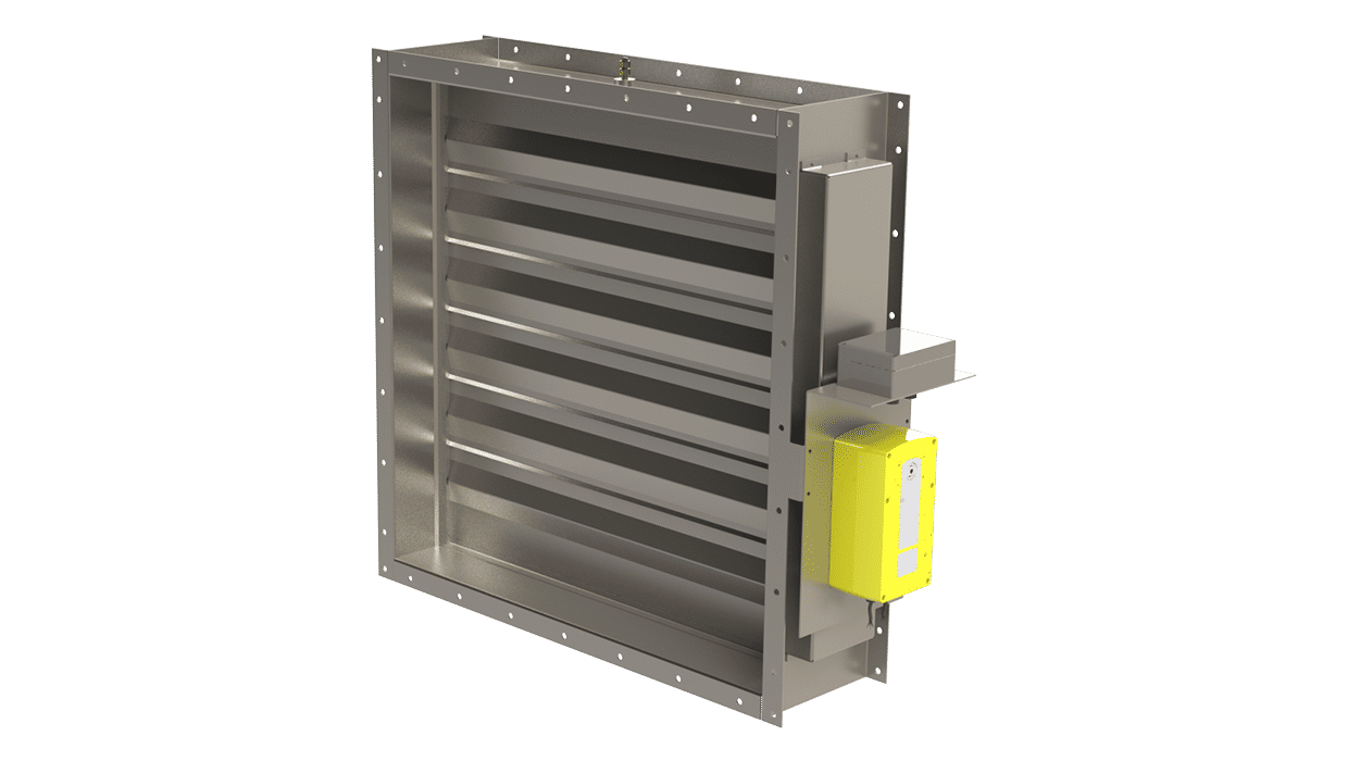
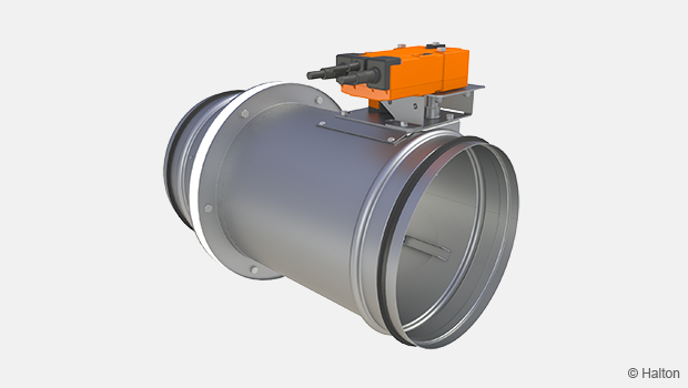
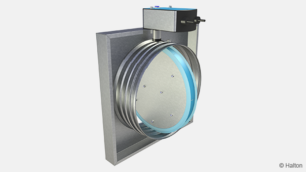
FDA – A0(A60) Fire and gas damper
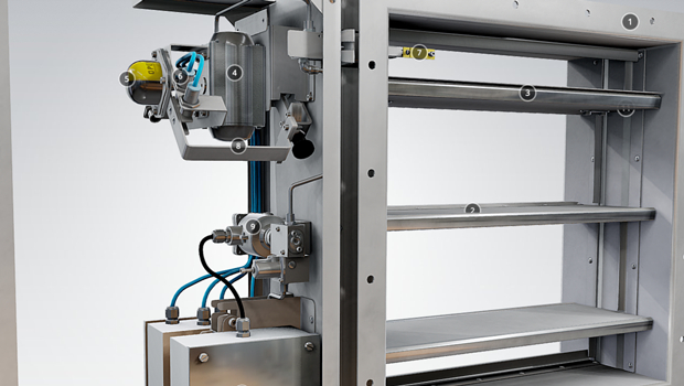
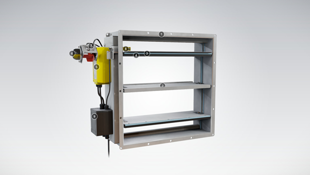
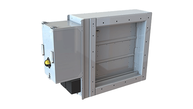
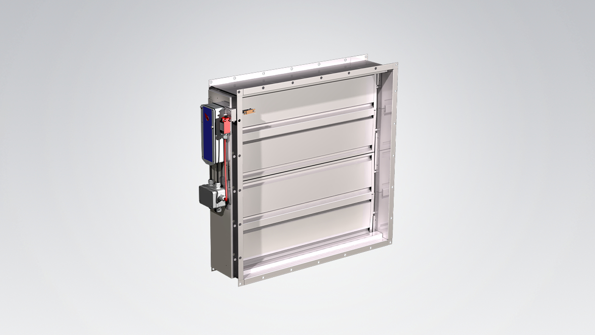
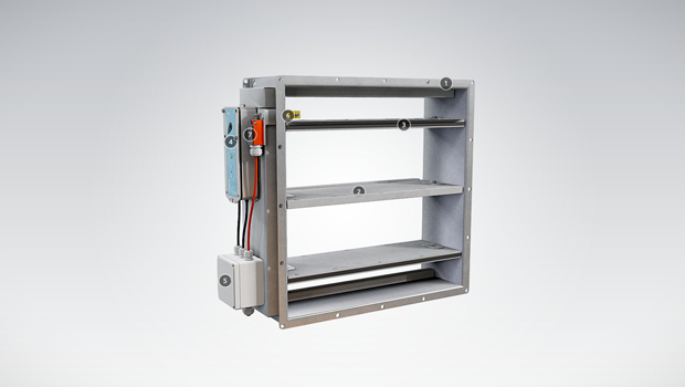
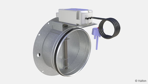
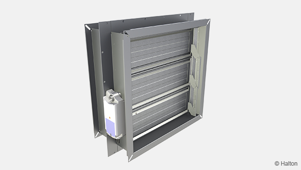
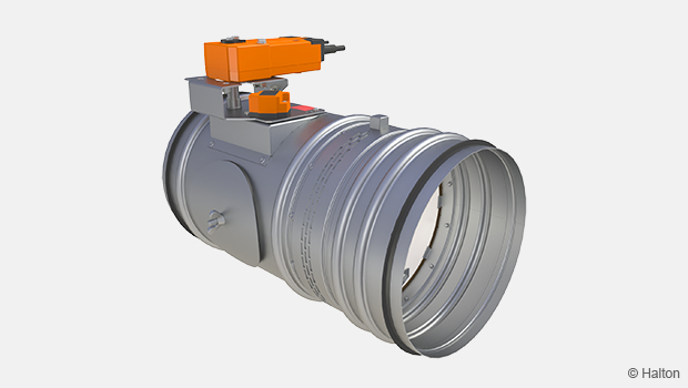
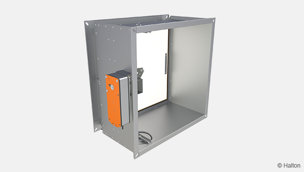
Halton FDA fire and gas damper – a new tighter fire and gas damper.

Overview
- Type-approved by most recognized classification societies: A0 without insulation, A-15 to A-60 when suitably insulated
- Blades contain stainless steel spring seals for low leakage in normal conditions and thermal expansion graphite seals (effective from 150ºC) to seal the damper in case of fire. Silicon sealing as an option
- Closed damper fulfills the requirement of leakage class 3 (EN1751:2014) for size > 300×300 mm and for size > 200×200 mm (silicon seals). Casing leakage class C
- The nominal strip fuse release temperature is 50 ºC, 74 ºC or 100 ºC. Other temperatures available
- Nominal glass bulb fuse release is available as an option with temperatures of 68 ºC or 93 ºC. Other temperatures available
- Low weight due to double skin blade structure
- Electrical or pneumatic operation system available
- Maximum duct pressure for damper construction 5000 Pa and maximum air velocity 15 m/s
- Normal operation temperature for damper between -50 ºC to +80 ºC. Actuator and component selection can affect this temperature range. Other temperatures available on request
- Available as ATEX/IECEx certified
- SIL 2 safety assessment certificate available for the damper on specific terms
Specification
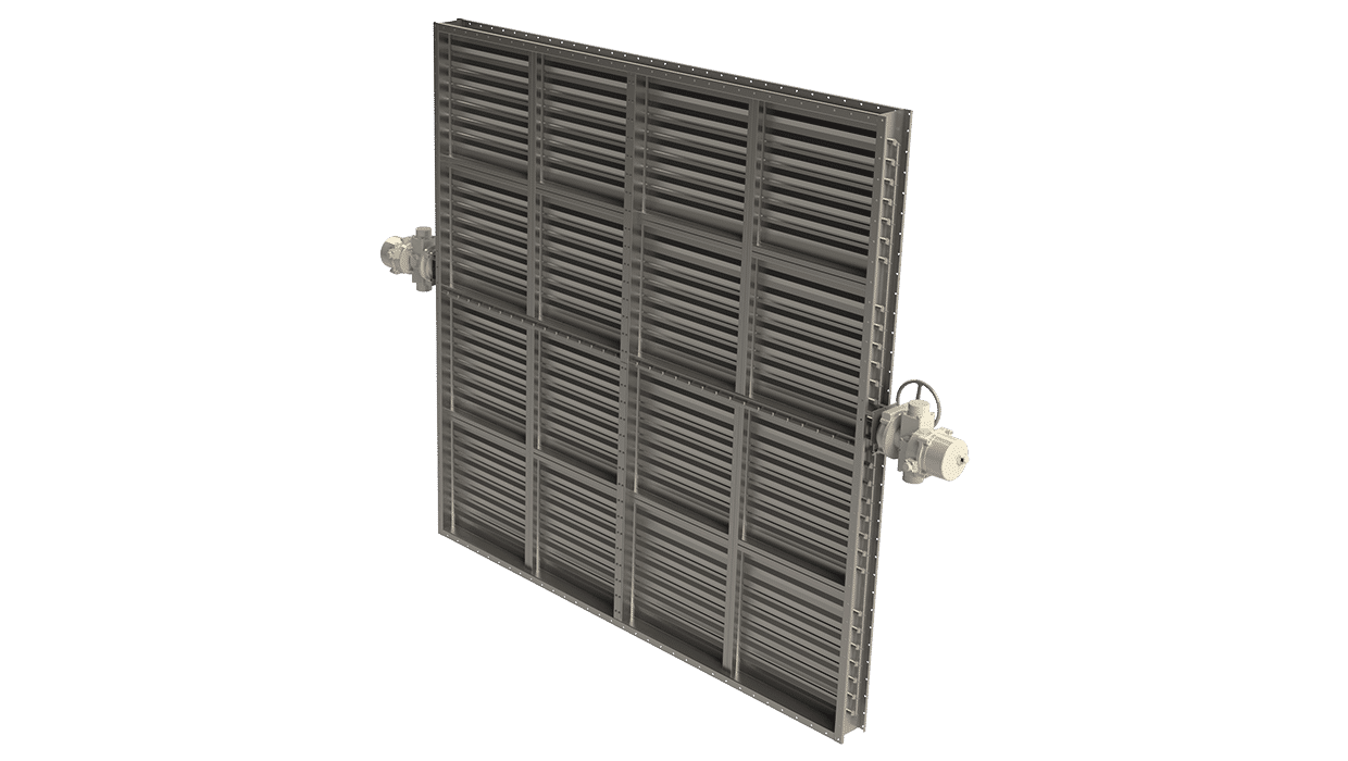
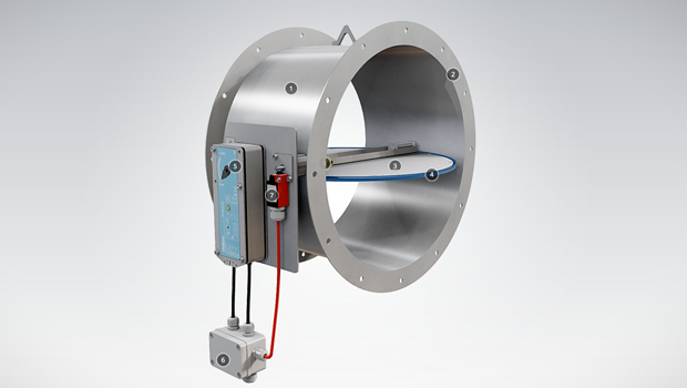
Halton FDA fire dampers are type-approved class A0(A60) fire and gas dampers for use in offshore, marine and navy ventilation systems. The FDA can be installed in rectangular or circular ducts. All fire dampers have a fusible link and they prevent the spread of fire and gases within the ventilation ductwork. When the blades are in the open position, the device does not cause significant pressure loss, noise or flow disturbance. An open-closed indicator is visible on the outside of the damper. Fire dampers with non-standard dimensions can be supplied on request.
Dimensions and Material Thickness
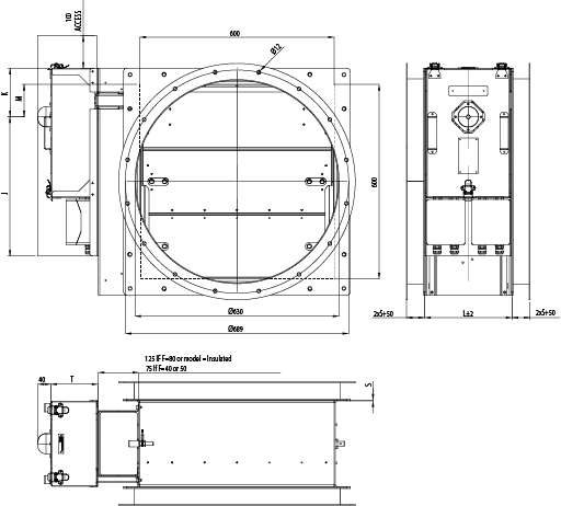
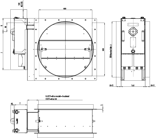
FDA fire dampers meet international standards for both rectangular (width B 200-1200 mm with 25 mm division and height H 200-1600 mm with 50 mm division) and circular ducts (Ø200-1250 mm). Modular constructions up to 2500×2600 mm available.
Non-standard dimensions and flange drilling available on request. Standard flanges and drilling according to ISO 15138 standards. Frame thickness 3 mm or 3-5 mm according to SOLAS.
Blades are made of two sheets, each of them being 1 mm thick (sandwich design).
Frame thickness according to SOLAS
| DIMENSIONS | S |
| If B or H > 100, but < 449 | 3 |
| If B or H > 450 but < 649 | 4 |
| If B or H > 650 | 5 |
Frame thickness according to SOLAS, Edition Dec. 2015
| DIMENSIONS | S |
| If A < 0.075 m2 | 3 |
| If A > 0.075 and A < 0.45 m2 | 4 |
| If A > 0.45 m2 | 5 |
Flange dimensions according to ISO 15138
| DIMENSIONS | ØC | F | P1 | P2 | BM |
| If longest side < 350 | 10 | 40 | 75…150 | 75…150 | 20 |
| If longest side 351…1000 | 12 | 50 | 75…150 | 75…150 | 30 |
| If longest side > 1001 | 14 | 80 | 75…150 | 75…150 | 40 |
Circular flange dimensions according to ISO 15138
| DIMENSIONS | ØC | F |
| If Ø D < 355 | 10 | 40 |
| If Ø D 356…1000 | 12 | 50 |
| If Ø D > 1001 | 14 | 80 |
FDA, General Drawings
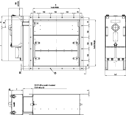
| Actuator | J | K | T |
| AT100 | 430 | 150 | 145 |
| AT100 + Halton smart override | 510 | 150 | 255 |
| AT200 | 510 | 150 | 165 |
| AT200 + Halton smart override | 510 | 150 | 275 |
| AT300 | 510 | 180 | 190 |
| AT300 + Halton smart override | 510 | 180 | 300 |
| Belimo BF | 430 | 150 | 125 |
| Belimo BF (Damper height<200) | 430 | 90 | 125 |
| Schischek S | 430 | 150 | 145 |
| Schischek S (Damper height<200) | 430 | 90 | 145 |
| Schischek S + Halton smart override | 440 | 220 | 235 |
| Schischek M | 510 | 150 | 175 |
| Schischek M + Halton smart override | 440 | 220 | 165 |
| H Normal height |
HF Free height |
M Drive |
| 200 | 200 | 100 |
| 250 | 250 | 125 |
| 300 | 250 | 125 |
| 350 | 250 | 125 |
| 400 | 400 | 100 |
| 450 | 450 | 125 |
| 500 | 500 | 125 |
| 550 | 500 | 125 |
| 600 | 600 | 100 |
| 650 | 650 | 125 |
| 700 | 700 | 125 |
| 750 | 750 | 125 |
| 800 | 800 | 100 |
| 850 | 850 | 125 |
| 900 | 900 | 125 |
| 950 | 950 | 125 |
| 1000 | 1000 | 125 |
| 1050 | 1050 | 125 |
| 1100 | 1100 | 125 |
| 1150 | 1150 | 125 |
| 1200 | 1200 | 125 |
| 1250 | 1250 | 125 |
| 1300 | 1300 | 125 |
| 1350 | 1350 | 125 |
| 1400 | 1400 | 125 |
| 1450 | 1450 | 125 |
| 1500 | 1500 | 125 |
| 1550 | 1500 | 125 |
| 1600 | 1500 | 125 |
| Material Thickness |
Depth |
| S | L |
| 3 | 270 |
| 4 | 272 |
| 5 | 275 |
Flange dimensions according to ISO 15138
| Nominal duct size (Ø D) |
Bolt circle (Ø E) | Bolt hole size (Ø C) |
No. of bolts |
| 100 | 145 | 10 | 4 |
| 125 | 170 | 10 | 4 |
| 150 | 195 | 10 | 4 |
| 160 | 205 | 10 | 4 |
| 200 | 245 | 10 | 8 |
| 250 | 295 | 10 | 8 |
| 275 | 320 | 10 | 8 |
| 300 | 345 | 10 | 8 |
| 315 | 360 | 10 | 8 |
| 355 | 400 | 10 | 8 |
| 400 | 459 | 12 | 8 |
| 450 | 509 | 12 | 12 |
| 500 | 559 | 12 | 12 |
| 560 | 619 | 12 | 12 |
| 600 | 659 | 12 | 16 |
| 630 | 689 | 12 | 16 |
| 700 | 759 | 12 | 16 |
| 710 | 769 | 12 | 16 |
| 800 | 859 | 12 | 24 |
| 900 | 959 | 12 | 24 |
| 1000 | 1059 | 12 | 24 |
| 1120 | 1209 | 14 | 24 |
| 1200 | 1289 | 14 | 32 |
| 1250 | 1339 | 14 | 32 |
| 1400 | 1489 | 14 | 32 |
Material and Finishing
| PART | MATERIAL | FINISHING |
| Frame | Carbon steel | Painted or galvanised |
| Frame | Stainless steel EN 1.4301 (AISI304), EN 1.4404 (AISI316L), EN 1.4432 (AISI316L) |
|
| Blades | Steel | Galvanised |
| Blades | Stainless steel EN 1.4301 (AISI304), EN 1.4404 (AISI316L), EN 1.4432 (AISI316L) |
– |
| Maintenance-free bearings | Oil bronze. Stainless steel EN 1.4404 (AISI316L) available as an option. | – |
| Shafts | Stainless steel EN 1.4404 (AISI316L) |
– |
Product Models and Accessories
Halton FDA is available with following actuators:
- FDA-EL: Electrical spring return actuator; standard actuators being 24 VAC/DC or 230 VAC or 120 VAC. Depending on the choice of actuator, the actuator might contain built-in open-closed limit switches. Separate junction box included in the EL-model. A wide range of Ex actuators available, including a one second closing time function as an option.
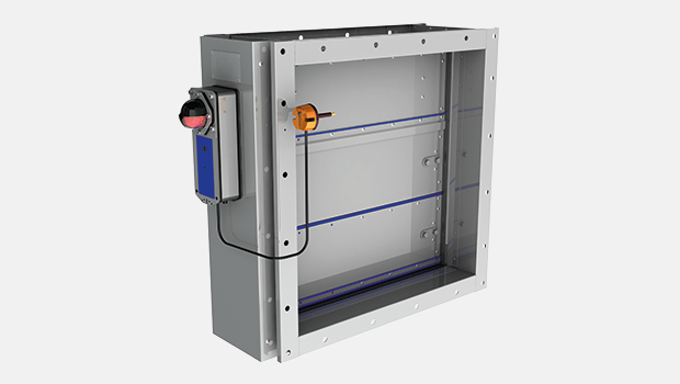
- FDA-PNR: Pneumatic rotating actuator
A wide range of accessories available.
Operation principles
In the event of a temperature rise in ductwork:
- FDA-EL: fusible link releases and cuts off operating voltage to the spring return motor, allowing the spring to close the damper blades. The fire damper opens automatically when the fuse has been changed and the operating voltage to the motor is re-established.
- FDA-PNR: fusible link releases and cuts off operating pressure to the spring return actuator, allowing springs to close the damper blades. The fire damper opens automatically when the fuse has been changed and the pneumatic air supply is re-established.
Weights
Weights of standard FDA dampers without actuator (KG). Frame thickness 3 mm.
| H/Height
(mm) |
B/Width (mm) | ||||||||||
| 200 | 300 | 400 | 500 | 600 | 700 | 800 | 900 | 1000 | 1100 | 1200 | |
| 200 | 18 | 20 | 23 | 26 | 29 | 32 | 35 | 38 | 40 | 43 | 46 |
| 300 | 21 | 24 | 27 | 29 | 32 | 35 | 38 | 41 | 44 | 47 | 49 |
| 400 | 26 | 29 | 33 | 36 | 39 | 42 | 46 | 49 | 52 | 56 | 59 |
| 500 | 30 | 33 | 36 | 40 | 43 | 46 | 50 | 53 | 56 | 59 | 63 |
| 600 | 35 | 39 | 42 | 46 | 50 | 54 | 57 | 61 | 65 | 69 | 72 |
| 700 | 39 | 42 | 46 | 50 | 54 | 57 | 61 | 65 | 69 | 72 | 76 |
| 800 | 44 | 48 | 52 | 56 | 60 | 65 | 69 | 73 | 77 | 81 | 86 |
| 900 | 47 | 52 | 56 | 60 | 64 | 68 | 73 | 77 | 81 | 85 | 89 |
| 1000 | 51 | 55 | 60 | 64 | 68 | 72 | 76 | 81 | 85 | 89 | 93 |
| 1100 | 56 | 61 | 66 | 70 | 75 | 80 | 84 | 89 | 93 | 98 | 103 |
| 1200 | 60 | 65 | 69 | 74 | 79 | 83 | 88 | 93 | 97 | 102 | 106 |
| 1300 | 65 | 70 | 75 | 80 | 86 | 91 | 96 | 101 | 106 | 111 | 116 |
| 1400 | 69 | 74 | 79 | 84 | 89 | 94 | 99 | 105 | 110 | 115 | 120 |
| 1500 | 73 | 78 | 83 | 88 | 93 | 98 | 103 | 108 | 113 | 119 | 124 |
| 1600 | 76 | 82 | 87 | 92 | 97 | 102 | 107 | 112 | 117 | 122 | 127 |
Approximate weights without an actuator. Flanges according to ISO 15138.
Weights of standard FDA dampers without actuator (KG). Frame thickness according to SOLAS (based on longest duct model).
| H/Height
(mm) |
B/Width (mm) | ||||||||||
| 200 | 300 | 400 | 500 | 600 | 700 | 800 | 900 | 1000 | 1100 | 1200 | |
| 200 | 18 | 21 | 24 | 31 | 34 | 43 | 48 | 52 | 56 | 60 | 65 |
| 300 | 21 | 24 | 27 | 35 | 38 | 48 | 52 | 57 | 61 | 65 | 69 |
| 400 | 26 | 30 | 33 | 42 | 46 | 57 | 62 | 66 | 71 | 76 | 80 |
| 500 | 34 | 38 | 42 | 46 | 50 | 62 | 67 | 72 | 76 | 81 | 86 |
| 600 | 40 | 45 | 49 | 54 | 48 | 71 | 76 | 81 | 86 | 92 | 97 |
| 700 | 50 | 56 | 61 | 66 | 71 | 76 | 81 | 87 | 92 | 97 | 102 |
| 800 | 57 | 63 | 68 | 74 | 79 | 85 | 91 | 96 | 102 | 107 | 113 |
| 900 | 62 | 68 | 73 | 79 | 85 | 90 | 96 | 101 | 107 | 113 | 118 |
| 1000 | 68 | 73 | 79 | 84 | 90 | 95 | 101 | 107 | 112 | 118 | 123 |
| 1100 | 74 | 80 | 86 | 92 | 98 | 104 | 110 | 116 | 122 | 128 | 134 |
| 1200 | 79 | 85 | 91 | 97 | 103 | 110 | 116 | 122 | 128 | 134 | 140 |
| 1300 | 86 | 92 | 99 | 105 | 112 | 118 | 125 | 131 | 138 | 144 | 151 |
| 1400 | 91 | 98 | 104 | 111 | 117 | 124 | 130 | 137 | 143 | 150 | 156 |
| 1500 | 96 | 103 | 109 | 116 | 122 | 129 | 135 | 142 | 148 | 155 | 161 |
| 1600 | 102 | 108 | 115 | 121 | 128 | 134 | 141 | 147 | 154 | 160 | 166 |
Approximate weights without an actuator. Flanges according to ISO 15138.
Weights of standard FDA dampers without actuator (KG). Frame thickness according to SOLAS Edition Dec. 2015 (based on duct cross-section area).
| H/Height
mm |
B / Width (mm) | ||||||||||
| 200 | 300 | 400 | 500 | 600 | 700 | 800 | 900 | 1000 | 1100 | 1200 | |
| 200 | 18 | 21 | 27 | 31 | 34 | 38 | 41 | 45 | 48 | 52 | 55 |
| 300 | 21 | 28 | 31 | 35 | 38 | 42 | 45 | 49 | 52 | 56 | 60 |
| 400 | 30 | 34 | 38 | 42 | 46 | 50 | 54 | 58 | 62 | 66 | 80 |
| 500 | 34 | 38 | 42 | 46 | 50 | 54 | 58 | 62 | 76 | 81 | 86 |
| 600 | 40 | 45 | 49 | 54 | 58 | 62 | 76 | 81 | 86 | 92 | 97 |
| 700 | 45 | 49 | 54 | 58 | 63 | 76 | 81 | 87 | 92 | 97 | 102 |
| 800 | 51 | 56 | 60 | 65 | 79 | 85 | 91 | 96 | 102 | 107 | 113 |
| 900 | 55 | 60 | 65 | 70 | 85 | 90 | 96 | 101 | 107 | 113 | 118 |
| 1000 | 60 | 65 | 70 | 84 | 90 | 95 | 101 | 107 | 112 | 118 | 123 |
| 1100 | 66 | 71 | 76 | 92 | 98 | 104 | 110 | 116 | 122 | 128 | 134 |
| 1200 | 70 | 75 | 91 | 97 | 103 | 110 | 116 | 122 | 128 | 134 | 140 |
| 1300 | 76 | 82 | 99 | 105 | 112 | 118 | 125 | 131 | 138 | 144 | 151 |
| 1400 | 80 | 86 | 104 | 111 | 117 | 124 | 130 | 137 | 143 | 150 | 156 |
| 1500 | 85 | 91 | 109 | 116 | 122 | 129 | 135 | 142 | 148 | 155 | 161 |
| 1600 | 90 | 108 | 115 | 121 | 128 | 134 | 141 | 147 | 154 | 160 | 166 |
Approximate weights without an actuator. Flanges according to ISO 15138.
Pneumatic actuators for FDA according to size of the damper
| H/Height (mm) |
B/Width (mm) | ||||||||||
| 200 | 300 | 400 | 500 | 600 | 700 | 800 | 900 | 1000 | 1100 | 1200 | |
| 200 | AT100 | AT100 | AT100 | AT100 | AT100 | AT100 | AT200 | AT200 | AT200 | AT200 | AT200 |
| 300 | AT100 | AT100 | AT100 | AT100 | AT100 | AT100 | AT200 | AT200 | AT200 | AT200 | AT200 |
| 400 | AT100 | AT100 | AT100 | AT100 | AT200 | AT200 | AT200 | AT200 | AT200 | AT200 | AT200 |
| 500 | AT100 | AT100 | AT100 | AT100 | AT200 | AT200 | AT200 | AT200 | AT200 | AT200 | AT200 |
| 600 | AT100 | AT100 | AT200 | AT200 | AT200 | AT200 | AT200 | AT200 | AT200 | AT300 | AT300 |
| 700 | AT100 | AT100 | AT200 | AT200 | AT200 | AT200 | AT200 | AT200 | AT200 | AT300 | AT300 |
| 800 | AT100 | AT100 | AT200 | AT200 | AT200 | AT200 | AT200 | AT300 | AT300 | AT300 | AT300 |
| 900 | AT100 | AT100 | AT200 | AT200 | AT200 | AT200 | AT200 | AT300 | AT300 | AT300 | AT300 |
| 1000 | AT100 | AT100 | AT200 | AT200 | AT200 | AT200 | AT200 | AT300 | AT300 | AT300 | AT300 |
| 1100 | AT100 | AT200 | AT200 | AT200 | AT200 | AT200 | AT300 | AT300 | AT300 | AT300 | AT300 |
| 1200 | AT100 | AT200 | AT200 | AT200 | AT200 | AT200 | AT300 | AT300 | AT300 | AT300 | AT300 |
| 1300 | AT100 | AT200 | AT200 | AT200 | AT200 | AT300 | AT300 | AT300 | AT300 | AT300 | AT300 |
| 1400 | AT100 | AT200 | AT200 | AT200 | AT200 | AT300 | AT300 | AT300 | AT300 | AT300 | AT300 |
| 1500 | AT100 | AT200 | AT200 | AT200 | AT200 | AT300 | AT300 | AT300 | AT300 | AT300 | AT300 |
| 1600 | AT100 | AT200 | AT200 | AT200 | AT200 | AT300 | AT300 | AT300 | AT300 | AT300 | AT300 |
Approximate weights of pneumatic rotary actuator Air Torque. FDA-PNR AT101 as aluminium +1,8 kg, AT104 as stainless steel 4,0 kg, AT201 as aluminium +3,2kg, AT204 as stainless steel +6,4 kg, AT301 as aluminium +6,0 kg, AT304 as stainless steel +13,3 kg.
Other actuators available on request.
Electrical actuators for FDA according to size of the damper
| H/Height (mm) | B/Width (mm) | ||||||||||
| 200 | 300 | 400 | 500 | 600 | 700 | 800 | 900 | 1000 | 1100 | 1200 | |
| 200 | Ex/Inmax-15-SF | Ex/Inmax-15-SF | Ex/Inmax-15-SF | Ex/Inmax-15-SF | Ex/Inmax-15-SF | Ex/Inmax-15-SF | Ex/Inmax-15-SF | Ex/Inmax-15-SF | Ex/Inmax-30-SF | Ex/Inmax-30-SF | Ex/Inmax-30-SF |
| 300 | Ex/Inmax-15-SF | Ex/Inmax-15-SF | Ex/Inmax-15-SF | Ex/Inmax-15-SF | Ex/Inmax-15-SF | Ex/Inmax-15-SF | Ex/Inmax-15-SF | Ex/Inmax-15-SF | Ex/Inmax-30-SF | Ex/Inmax-30-SF | Ex/Inmax-30-SF |
| 400 | Ex/Inmax-15-SF | Ex/Inmax-15-SF | Ex/Inmax-15-SF | Ex/Inmax-15-SF | Ex/Inmax-15-SF | Ex/Inmax-30-SF | Ex/Inmax-30-SF | Ex/Inmax-30-SF | Ex/Inmax-30-SF | Ex/Inmax-30-SF | Ex/Inmax-30-SF |
| 500 | Ex/Inmax-15-SF | Ex/Inmax-15-SF | Ex/Inmax-15-SF | Ex/Inmax-15-SF | Ex/Inmax-15-SF | Ex/Inmax-30-SF | Ex/Inmax-30-SF | Ex/Inmax-30-SF | Ex/Inmax-30-SF | Ex/Inmax-30-SF | Ex/Inmax-30-SF |
| 600 | Ex/Inmax-15-SF | Ex/Inmax-15-SF | Ex/Inmax-15-SF | Ex/Inmax-30-SF | Ex/Inmax-30-SF | Ex/Inmax-30-SF | Ex/Inmax-30-SF | Ex/Inmax-30-SF | Ex/Inmax-30-SF | Ex/Inmax-30-SF | Ex/Inmax-30-SF |
| 700 | Ex/Inmax-15-SF | Ex/Inmax-15-SF | Ex/Inmax-15-SF | Ex/Inmax-30-SF | Ex/Inmax-30-SF | Ex/Inmax-30-SF | Ex/Inmax-30-SF | Ex/Inmax-30-SF | Ex/Inmax-30-SF | Ex/Inmax-30-SF | Ex/Inmax-30-SF |
| 800 | Ex/Inmax-15-SF | Ex/Inmax-15-SF | Ex/Inmax-30-SF | Ex/Inmax-30-SF | Ex/Inmax-30-SF | Ex/Inmax-30-SF | Ex/Inmax-30-SF | Ex/Inmax-30-SF | Ex/Inmax-30-SF | Ex/Inmax-50-SF | Ex/Inmax-50-SF |
| 900 | Ex/Inmax-15-SF | Ex/Inmax-15-SF | Ex/Inmax-30-SF | Ex/Inmax-30-SF | Ex/Inmax-30-SF | Ex/Inmax-30-SF | Ex/Inmax-30-SF | Ex/Inmax-30-SF | Ex/Inmax-30-SF | Ex/Inmax-50-SF | Ex/Inmax-50-SF |
| 1000 | Ex/Inmax-15-SF | Ex/Inmax-15-SF | Ex/Inmax-30-SF | Ex/Inmax-30-SF | Ex/Inmax-30-SF | Ex/Inmax-30-SF | Ex/Inmax-30-SF | Ex/Inmax-30-SF | Ex/Inmax-30-SF | Ex/Inmax-50-SF | Ex/Inmax-50-SF |
| 1100 | Ex/Inmax-15-SF | Ex/Inmax-15-SF | Ex/Inmax-30-SF | Ex/Inmax-30-SF | Ex/Inmax-30-SF | Ex/Inmax-30-SF | Ex/Inmax-30-SF | Ex/Inmax-50-SF | Ex/Inmax-50-SF | Ex/Inmax-50-SF | Ex/Inmax-50-SF |
| 1200 | Ex/Inmax-15-SF | Ex/Inmax-15-SF | Ex/Inmax-30-SF | Ex/Inmax-30-SF | Ex/Inmax-30-SF | Ex/Inmax-30-SF | Ex/Inmax-30-SF | Ex/Inmax-50-SF | Ex/Inmax-50-SF | Ex/Inmax-50-SF | Ex/Inmax-50-SF |
| 1300 | Ex/Inmax-15-SF | Ex/Inmax-30-SF | Ex/Inmax-30-SF | Ex/Inmax-30-SF | Ex/Inmax-30-SF | Ex/Inmax-30-SF | Ex/Inmax-50-SF | Ex/Inmax-50-SF | Ex/Inmax-50-SF | Ex/Inmax-50-SF | Ex/Inmax-50-SF |
| 1400 | Ex/Inmax-15-SF | Ex/Inmax-30-SF | Ex/Inmax-30-SF | Ex/Inmax-30-SF | Ex/Inmax-30-SF | Ex/Inmax-30-SF | Ex/Inmax-50-SF | Ex/Inmax-50-SF | Ex/Inmax-50-SF | Ex/Inmax-50-SF | Ex/Inmax-50-SF |
| 1500 | Ex/Inmax-15-SF | Ex/Inmax-30-SF | Ex/Inmax-30-SF | Ex/Inmax-30-SF | Ex/Inmax-30-SF | Ex/Inmax-30-SF | Ex/Inmax-50-SF | Ex/Inmax-50-SF | Ex/Inmax-50-SF | Ex/Inmax-50-SF | Ex/Inmax-50-SF |
| 1600 | Ex/Inmax-15-SF | Ex/Inmax-30-SF | Ex/Inmax-30-SF | Ex/Inmax-30-SF | Ex/Inmax-30-SF | Ex/Inmax-30-SF | Ex/Inmax-50-SF | Ex/Inmax-50-SF | Ex/Inmax-50-SF | Ex/Inmax-50-SF | Ex/Inmax-50-SF |
Electric rotary actuator Schischek ExMax or InMax
| ACTUATOR OPTIONS | CLOSING TIME | MATERIAL | WEIGHT (APPR.) |
| Ex/InMax-15-SF | 3 seconds | Aluminium | 3,5 kg |
| Ex/InMax-15-SF | 3 seconds | Stainless steel | 7,0 kg |
| Ex/InMax-15-SF1 | 1 second | Aluminium | 3,5 kg |
| Ex/InMax-15-SF1 | 1 second | Stainless steel | 7,0 kg |
| Ex/InMax-30-SF3 | 3 second | Aluminium | 9,5 kg |
| Ex/InMax-50-SF3 | 3 second | Aluminium | 9,5 kg |
Installation
Installation on wall or roof.
At wall installation the blade orientation must always be in horizontal plane.
Copies of Installation, Operation and maintenance manuals are available from Halton Marine Sales offices and distributors.
Product Code
(S)=Shape of Connection
(A) Circular (D1)
(C ) Circular (D2)
(R) Rectangular
(W)=Width
200-1200
step 25 mm
(H)=Height
200-1600
step 50 mm
(D)=Diameter
200-1200
step max(step W, step H) = step H = 50 mm
Specifics and accessories
(EX)=Atex Class
(NA) No ATEX class (safe area)
(X1) EX II 2 G (Zone 1)
(SF)=Flange Option
(N0) Connection flange in circular connections ISO15138
(N1) Connection + loose flange in circular connections ISO15138
(NA) Not Assigned (circular connection)
(NR) Flanges (2 sides) ISO15138
(FS)=Frame Dimensioning
(N0) Connection flange in circular connections ISO15138
(N1) Connection + loose flange in circular connections ISO15138
(NA) Not Assigned (circular connection)
(NR) Flanges (2 sides) ISO15138
(MA)=Material
(AS) Stainless steel (1.0) EN1.4404
(CS) Carbon steel (1.0)
(LS) Stainless steel (1.0) EN1.4432
(SS) Stainless steel (1.0) EN1.4301
(FM)=Frame Material
(A3) Stainless steel (3.0) EN1.4404
(A3) Stainless steel (4.0) EN1.4404
(A3) Stainless steel (5.0) EN1.4404
(C3) Carbon steel (3.0)
(C4) Carbon steel (4.0)
(C5) Carbon steel (5.0)
(L3) Stainless steel (3.0) EN1.4432
(L4) Stainless steel (4.0) EN1.4432
(L5) Stainless steel (5.0) EN1.4432
(S3) Stainless steel (3.0) EN1.4301
(S4) Stainless steel (4.0) EN1.4301
(S5) Stainless steel (5.0) EN1.4301
(FI)=Finishing
(HG) Hot galvanized
(NA) Not Assigned (acid treatment)
(PN) Painting
(PX) Special Painting C5-M ISO12944
(BM)=Bearing Material
(BR) Phosphor-bronze-iolite
(AS) Stainless steel EN1.4404
(IN)=Insulation
(N) No insulation
(Y) Insulation
(RE)=Actuator
(I1) InMax 15-SF
(I2) InMax 15-SF VAS
(I3) InMax 15-SF1 VAS
(I5) InMax 30-SF3
(I6) InMax 15-SF1
(I7) InMax 50-SF3
(P0) Pneumatic – Air Torque, AT101, Aluminium
(P3) Pneumatic – Air Torque, AT104, AISI316
(P4) Pneumatic – Air Torque, AT201 FA, Aluminium
(P5) Pneumatic – Air Torque, AT204 FA, AISI316
(Q5) Pneumatic -Air Torque, AT301 FA, Aluminium
(Q6) Pneumatic – Air Torque, AT304 FA, AISI316
(Q7) Pneumatic – Air Torque, AT351 FA, Aluminium, Module
(Q8) Pneumatic – Air Torque, AT404 FA, AISI316, Aluminium, Module
(U0) Pneumatic – Air Torque, AT301 FA STR, Aluminium
(U1) Pneumatic – Air Torque, AT304 FA STR, AISI316
(U2) Pneumatic – Air Torque, AT351 FA STR, Aluminium, Module
(U3) Pneumatic – Air Torque, AT404 FA STR, AISI316, Module
(Z2) Ex-proofed ExMax 15-SF
(Z4) Ex-proofed ExMax 15-SF VAS
(Z5) Ex-proofed ExMax 15-SF1 VAS
(Z7) Ex-proofed ExMax 15-SF1
(Y1) Ex-proofed ExMax 30-SF3
(Y3) Ex-proofed ExMax 50-SF3
(FU)=Fuse
144 °C
100 °C
95 °C
74 °C
72 °C
70 °C
65 °C
50 °C
(AC)=Accessories
(L2) Limit switch 2 pcs IP65 (Plastic) (Bernstein)
(L4) EX Limit switch 2 pcs (Plastic) (Bartec)
(L5) EX Limit switch 4 pcs (Plastic) (Bartec)
(L6) EX Magnetic switch 2 pcs (AISI6118) (Elobau)
(L7) EX Magnetic switch 4 pcs (AISI6118) (Elobau)
(M1) Solenoid valve 24 VDC (Aluminium) (SMC)
(M2) Solenoid valve 230 VAC (Aluminium) (SMC)
(M3) EX solenoid valve 24 VDC (Brass) (ASCO)
(M4) EX solenoid valve 230 VAC (SS) (ASCO)
(M5) EX solenoid valve 24 VDC (AISI316) (Bifold)
(P1) Pneumatic valve manual (Aluminum) (SMC)
(P2) Pneumatic valve manual (AISI316) (Bifold)
(SC) Stainless steel cover box (Steel) (Halton)
(ST) Stainless steel tubing (AISI316) (Halton)
(O1) Halton Smart Override, manual EL Ex/InMax S-serie
(O2) Halton Smart Override, manual PN AT100, 200
(O3) Halton Smart Override, manual PN AT300, 350, 400
(O4) Halton Smart Override, manual EL Ex/InMax M-serie
Code example
FDA/R-1200-1600,EX=X1,SF=NR,FS=SO,MA=CS,FM=C5,FI=HG,BM=AS,IN=N,RE=P4,FU=74,ZT=Y,AC=E2,L8,M4,SC,O2
Downloads
-
Halton FDA datasheet 2025
Data
English -
Halton FDA datasheet 2020 – Chinese
Data
Chinese -
ABS Certificate for Halton FDA
Data
English -
DNV Certificate for Halton FDA
Data
English -
EAC Certificate for Halton FDA, FDB2, FDO, FDH, FCE, UTA, UTG, BDH, BRD, BLD
Data
Русский (ru) -
LR Certificate for Halton FDA
Data
English -
LR Transport Canada Certificate for Halton FDA
Data
English -
MED BV Certificate for Halton FDA
Data
English -
RMRS Certificate for Halton FDA
Data
Русский (ru) -
Halton Marine Oy MED Quality System Module D Certificate
Data
English -
SIL 2 Safety Assessment Certificate
Data
English -
ATEX Certificare for FDB2, FDL, FDO, FDA
Data
English
Request for Quotation
"*" indicates required fields
CFD-01 – A0 (A60) E120S Fire damper
product
CFD-02TM – High temperature tunnel damper
product
FCE – Fire damper (EI 60 S)
product
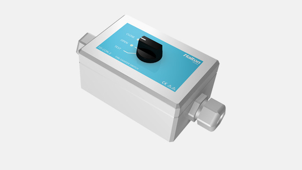
FD-CON-2 – Fire damper control unit
product
FD-CON-A – Fire damper control unit
product
FDA – A0(A60) Fire and gas damper
product
FDB2 – A0(A60) Fire and gas damper
product
FDH – H0(H120) Fire and gas damper
product
FDK – A0(A60) Fire damper
product
FDL – A0(A60) Fire damper
product
FDO – A0(A60) Fire and gas damper
product
Halton Exe EDC – Fire damper (EI 120 S)
product
Halton Exe EFC – Fire damper (EI 120 S)
product
Halton Exe ELC – Fire damper (E 120 S)
product
Halton Exe ELR – Fire damper (E 120 S)
product
Halton Exe ESC – Fire damper (EI 120 S)
product
Halton Exe ESR – Fire damper (EI 120 S)
product
Halton Exe ETC – Fire damper (EI 120 S)
product

Halton Exe ETR – Fire damper (EI 120 S)
product
Halton FDI – Fire damper (EI 60 S)
product