Product / CFD01
CFD-01 – A0 (A60) E120S Fire damper
Designed to operate in the most arduous conditions and extremes of climate and temperature, Flamgard Calidair dampers have a proven record of reliability and high performance across multiple industries.
Overview
- Certified IMO Annex FTP 1, Part 3 certified by Lloyds Register of Shipping, DNV, ABS and BV.
- Type tested/approved and compliant to EN1366-2 Fire Resistant to E (Integrity) S (Smoke) and I (Insulation) from 30 to 120 minutes. (Patented).
- BS 15650 accredited.
- Type tested/approved for Hydrocarbon applications H0-H120.
- Type tested/approved BS476
- Type tested/approved GOST R 55301-2009. (Patented).
- NORSOK case and blade leakage compliant.
- Case and Blade leakage compliant to EN 1751.
- Independent SIL2 Certified
- ATEX Compliant.
- ISO 9001:2015 accredited
- Independent Pressure Drop Tested
- Independent Noise Tested
- Independent Seismic and Blast tested
Specification
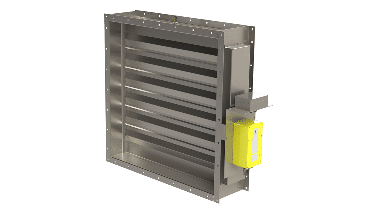
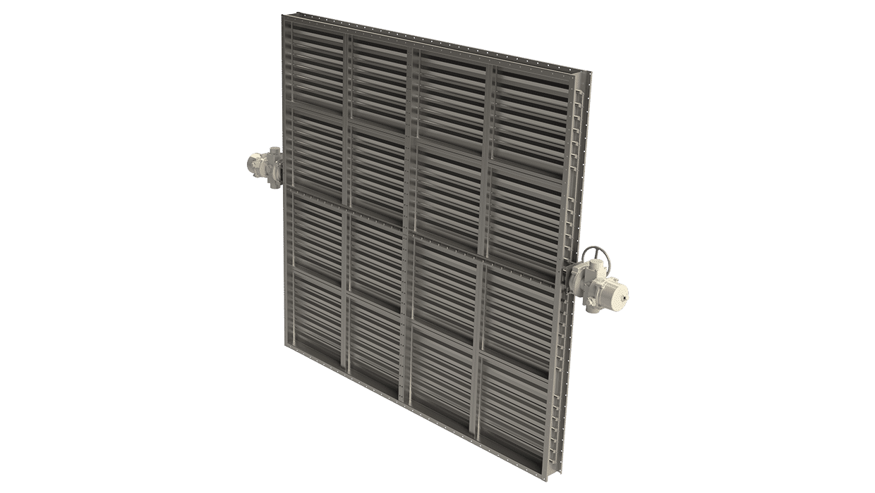
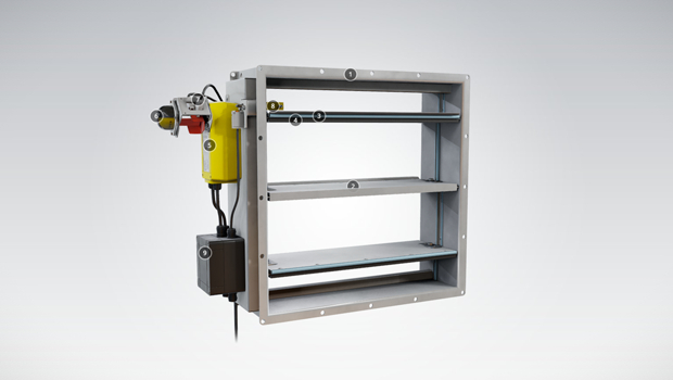
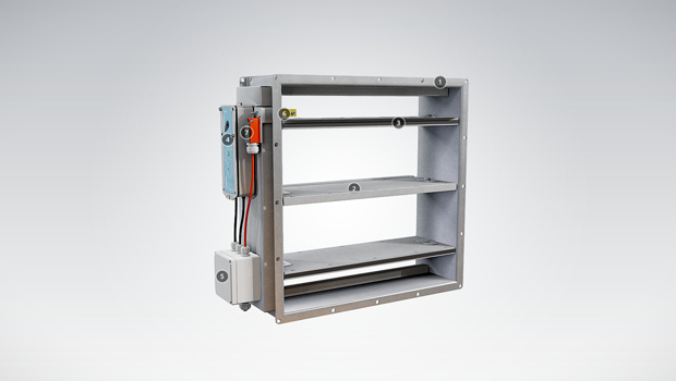
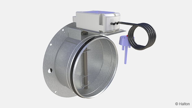
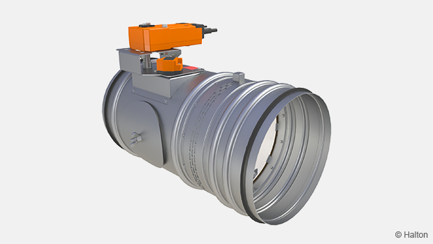
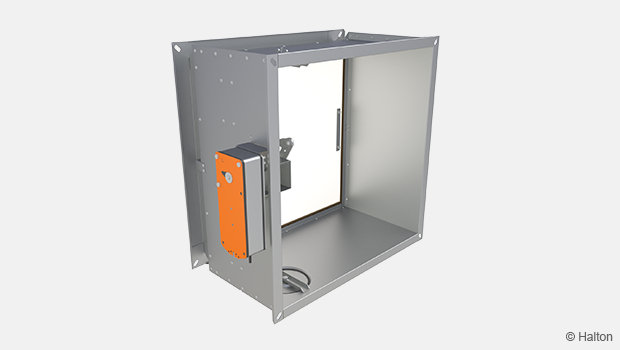
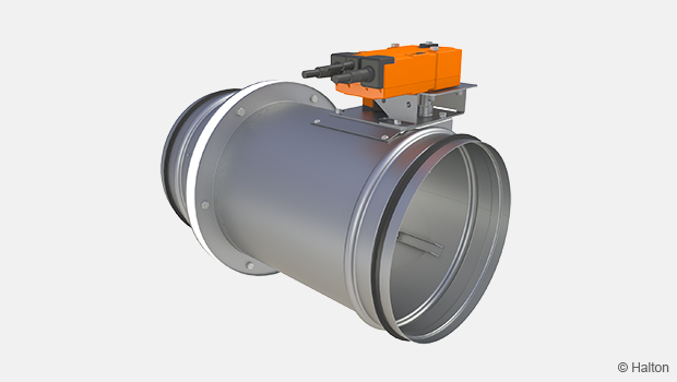
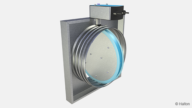
The type CFD-01 Fire and Smoke Dampers are utilised in ventilation systems to prevent the passing and spread of fire and smoke between designated divisions. The Flamgard Calidair Fire Damper is designed for bolting to steel bulkheads & decks, fixing to walls or floors or connecting directly to ductwork. All bolted connections are made via integral bolted angle flanges. The damper has been successfully tested to global international standards highlighted above.
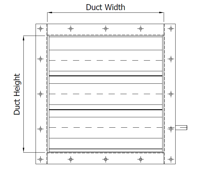
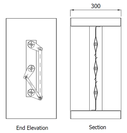
Dimensions
Casing
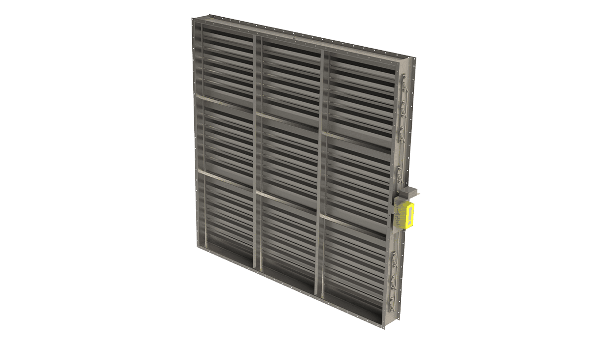
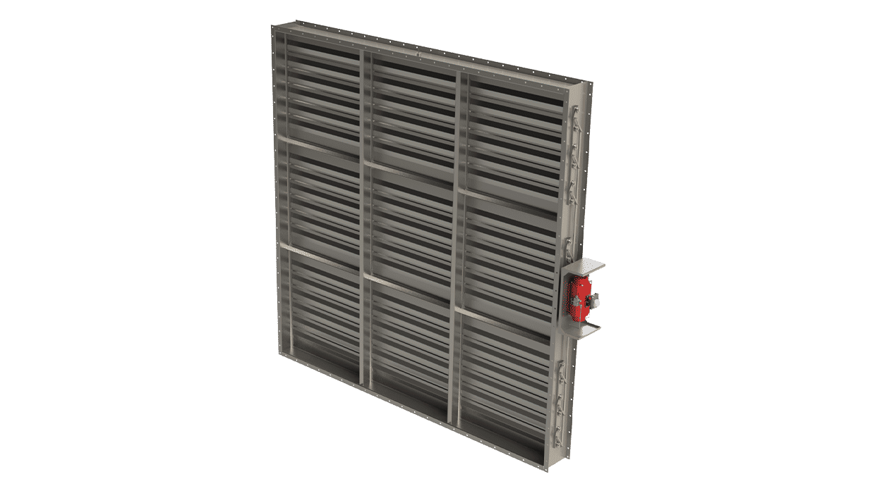
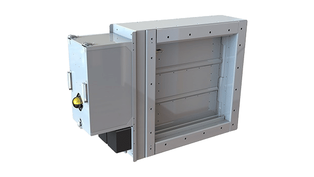
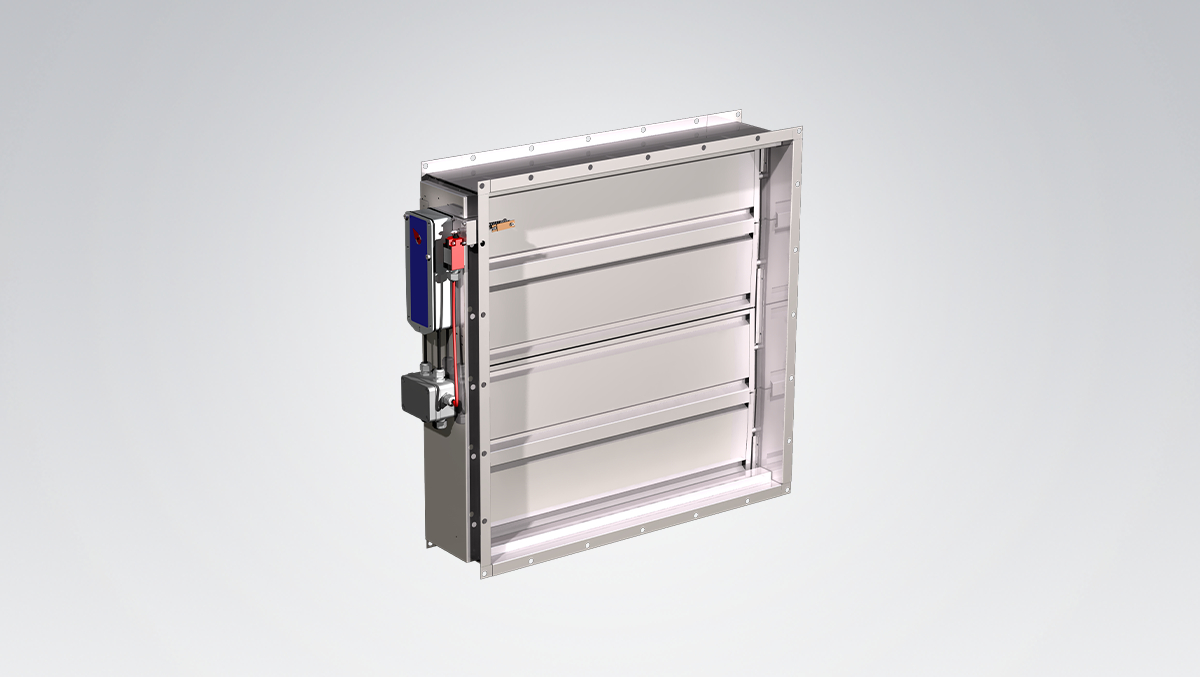
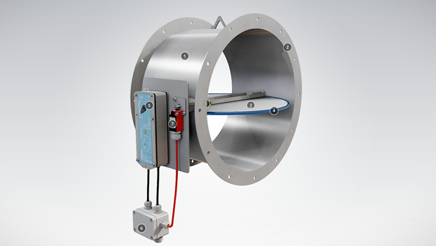
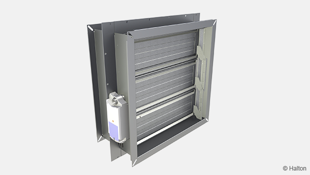
The damper casing is formed from 3.0 mm thick sheet steel into a rigid channel section to ensure proper alignment of blades and shafts. Fire dampers are available as single units or as multi-module assemblies, with a maximum overall size of 2050 mm × 2050 mm. Where circular dampers or dampers with width or height dimensions less than 150 mm are required, additional spigot adaptors are used which increase the damper insertion length from 300 to 400 mm.
Blades
The blades are a formed double-skin aerofoil section of 1.5 mm sheet metal which operate on the ‘Firelock’ principle creating a 3-pass labyrinth between the blades which fire cannot penetrate. Blade stops at the top and bottom of the casing and sprung side seals provide excellent low leakage characteristics. Dependent on market sector or required certification of the Damper additional patented sealing and blade materials are utilized.
Shafts
Continuous Ø 19.05 mm with blades plug welded at each end.
CFD-01 General Drawings
Material and Finishing
| Part | Material | Finishing |
| Case | Mill Galvanised Mild Steel | Mill Finish |
| Case | Stainless Steel – 1.4307 (304L) Stainless Steel – 1.4404 (316L) |
Typically 2B finish |
| Blades | Mill Galvanised Mild Steel | Mill Finish |
| Blades | Stainless Steel – 1.4307 (304L) Stainless Steel – 1.4404 (316L) |
Typically 2B finish |
| Shafts | Stainless Steel – 1.4307 (304L) Stainless Steel – 1.4404 (316L) |
– |
| Bearings | Oil Impregnated Sintered Bronze (other options available on request) |
– |
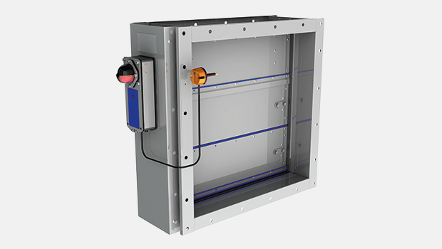
Product Models and Accessories
Flamgard Calidair CFD-01 Fire and Smoke Dampers are available with the following actuators:
- Manually operated damper with a spring pack and fusible link.
- Pneumatic spring return actuator.
- Electronic spring return actuators with a voltage range between 24V to 430V. Including models that can be used in Ex areas and hazardous locations.
- Electro-hydraulic actuators
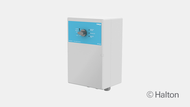
Damper control systems can be mounted within an enclosure to protect them from the elements and mechanical damage.
Dampers can be fitted with a with a range of controls components for safe and hazardous areas including suitable IP ratings where required.
For available options please contact sales team for more information.
Operation Principle
Under normal operation, Fire Dampers will remain in the open position allowing for the ventilation of the associated areas. By definition, Fire Dampers must fail-safe closed to protect the rating of the fire division. This is typically achieved using a spring return system ensuring the damper closes even on loss of power.
Automatic operation in the event of a temperature rise in ductwork:
- The fusible link will release and thus allowing the mechanical spring pack to close the dampers blades.
- The fusible link releases and operating pressure will be cut off to the pneumatic actuator, thus causing the damper blades to close fully.
- The fusible link releases and operating voltage will be cut off to the electric actuator, thus allowing the spring to close the damper blades fully.
Additional operations may include
- Remote operation of the fire damper.
- Local operation of the fire damper.
- Remote indication of the fire dampers status.
- Local indication of the fire dampers status.
- Facility for automatic operation from fire or gas detection systems.
- Facility for ‘black start’ operation.
Weights
Please note the below table gives bare shaft damper weights only at the given square dimensions. Weights for specific sizes are issued on the quotation document.
| Damper size (mm) | Est. weight | ||
| Width/Dia. | Height | Depth | |
| 150 | 150 | 300 | 10 kg |
| 200 | 200 | 300 | 12 kg |
| 250 | 250 | 300 | 15 kg |
| 300 | 300 | 300 | 20 kg |
| 350 | 350 | 300 | 23 kg |
| 400 | 400 | 300 | 26 kg |
| 450 | 450 | 300 | 31 kg |
| 500 | 500 | 300 | 35 kg |
| 550 | 550 | 300 | 39 kg |
| 600 | 600 | 300 | 44 kg |
| 650 | 650 | 300 | 48 kg |
| 700 | 700 | 300 | 53 kg |
| 750 | 750 | 300 | 59 kg |
| 800 | 800 | 300 | 64 kg |
| 850 | 850 | 300 | 68 kg |
| 900 | 900 | 300 | 76 kg |
| 950 | 950 | 300 | 81 kg |
| 1000 | 1000 | 300 | 86 kg |
Installation
Dampers are typically provided with integral drilled flanges that allow for bolting to ductwork, structural divisions, wall sleeves and similar. Flanges and drillings can be to Flamgard standard or customer specification.
Dampers can be fitted in any orientation with airflow in either direction.
Installation and maintenance instructions can be provided with each damper delivery.
Downloads
Request for Quotation
"*" indicates required fields
CFD-01 – A0 (A60) E120S Fire damper
product
CFD-02TM – High temperature tunnel damper
product
FCE – Fire damper (EI 60 S)
product
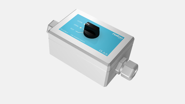
FD-CON-2 – Fire damper control unit
product
FD-CON-A – Fire damper control unit
product

FDA – A0(A60) Fire and gas damper
product
FDB2 – A0(A60) Fire and gas damper
product
FDH – H0(H120) Fire and gas damper
product
FDK – A0(A60) Fire damper
product
FDL – A0(A60) Fire damper
product
FDO – A0(A60) Fire and gas damper
product
Halton Exe EDC – Fire damper (EI 120 S)
product
Halton Exe EFC – Fire damper (EI 120 S)
product
Halton Exe ELC – Fire damper (E 120 S)
product
Halton Exe ELR – Fire damper (E 120 S)
product
Halton Exe ESC – Fire damper (EI 120 S)
product
Halton Exe ESR – Fire damper (EI 120 S)
product
Halton Exe ETC – Fire damper (EI 120 S)
product

Halton Exe ETR – Fire damper (EI 120 S)
product
Halton FDI – Fire damper (EI 60 S)
product