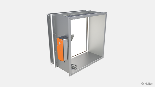
Product / FDV
Overview
- Possible to install in concrete, masonry or lightweight wall with fire resistance of
E 120 (ve – ho ) S or EI 15 (ve ) S in concrete slab EI 30 (ho ) S - Suitable for vertical and horizontal installation Ve, Ho
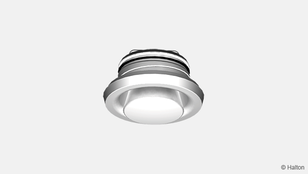
- Fuse 72 °C inside cone
- The integral installation frame is equipped with a sealing gasket and fire seal at its flange.
- Manufactured in accordance with ISO 9001 quality system.
Quick selection

Dimensions and weight
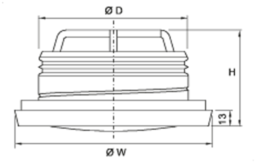
| NS [mm] |
ØW [mm] |
H [mm] |
ØD [mm] |
Weight [mm] |
| 100 | 139 | 88 | 99 | 0.4 |
| 125 | 165 | 88 | 124 | 0.5 |
| 160 | 200 | 88 | 159 | 0.7 |
| 200 | 251 | 86 | 199 | 1.0 |
Material
| Part | Material | Note |
| Collar | Steel | Epoxy painted |
| Central cone | Steel | Epoxy painted |
| Frame gasket | Polyurethane | – |
| Fireproof gasket | Silicate | – |
| Installation frame | Galvanised steel | – |
| Melting fuse | Brass | – |
Function
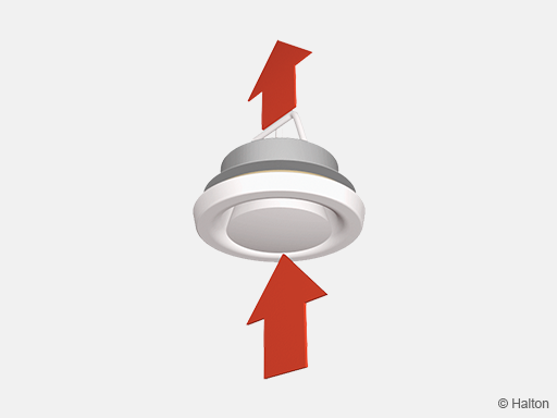
The Halton FDV is a circular fire valve. It prevents fire and smoke from spreading in ventilation ducts.
Operation as an exhaust valve normal mode
The valve throttles the exhaust airflow and attenuates the duct noise. The pressure drop is dependent on the position of the central cone. The desired exhaust rate is set during the balancing of the air flows in a ductwork system.
Operation as a fire damper emergency mode
The fire damper contains an integral thermal fuse. This fuse responds to a rise in temperature, which causes a spring-return central cone to close.
The thermal fuse is released at 72°C.
Installation
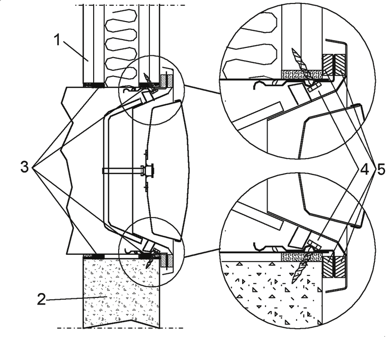
Key
1. Lightweight wall
2. Concrete or masonry wall or ceiling
3. Fire-stop mass (Würth Firebreak 22)
4. Screws
5. Fireproof silicate gaskets
The Halton FDV fire valve is approved for installation on concrete or masonry walls and ceilings and on lightweight walls.
Make an opening in the separating element for the air duct to be led through the structure.
The size of the installation opening is D + 20 mm.
Install the duct in the opening. Create the fire seal between duct and wall with a fire-stop mass (Würth Firebreak 22) and rockwool as indicated in the picture. Cut the duct flush with the wall surface.
Push the installation frame into the duct so that the flange is firmly pressed against the wall surface. Attach the installation to the duct and wall with two screws.
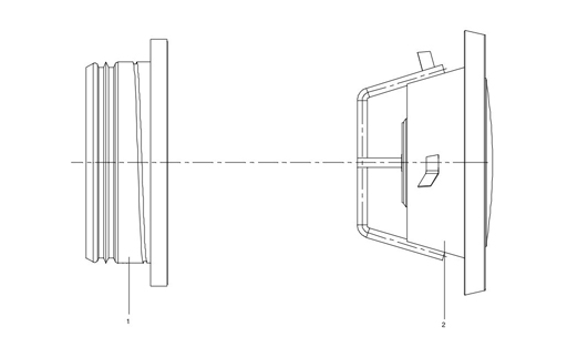
Push the valve (2) into the installation frame (1), and turn until it is firmly attached.
Detailed installation instructions, as well as an installer’s installation certificate form, are supplied with each product. For further information see also tab Documents / Installation Instructions .
Adjustment
The Halton FDV valve is adjusted by rotating the central cone. Measure the opening (A) position (in mm) of the central cone. Set a probe inside the valve, and measure the differential pressure with a manometer. The air flow rate is calculated by using the formula below. After the adjustment, lock the central cone with the locking nut.

| FDV 100 | FDV 125 | FDV 160 | FDV 200 | |||||||
| A | k | A | k | A | k | A | k | |||
| -15 | 0,43 | -15 | 0,65 | -12 | 1,16 | 3 | 1,78 | |||
| -12 | 0,63 | -12 | 0,92 | -9 | 1,51 | 6 | 2,46 | |||
| -9 | 0,83 | -9 | 1,22 | -6 | 1,9 | 9 | 3,24 | |||
| -6 | 1,02 | -6 | 1,53 | -3 | 2,31 | 12 | 3,97 | |||
| -3 | 1,22 | -3 | 1,84 | 0 | 2,75 | 15 | 4,69 | |||
| 0 | 1,42 | 0 | 2,17 | 3 | 3,25 | 20 | 5,88 | |||
| 3 | 1,65 | 3 | 2,52 | 6 | 3,73 | 25 | 6,95 | |||
| 6 | 1,88 | 6 | 2,83 | 9 | 4,22 | – | – | |||
| 9 | 2,11 | 9 | 3,14 | 12 | 4,67 | – | – | |||
| 12 | 2,33 | 12 | 3,46 | 15 | 5,12 | – | – | |||
| 15 | 3,77 | 18 | 5,58 | – | – | |||||
 –
–
Servicing
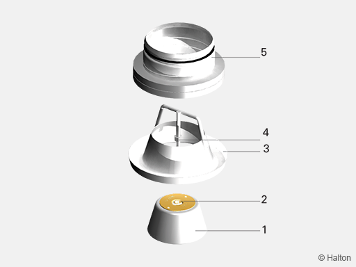
Key
1. Central cone
2. Fuse
3. Collar
4. Locking nut
5. Frame
Loosen the Halton FDV valve from the ductwork by turning anti-clockwise. Note the adjusted opening position of the central cone.
Wipe the parts with a damp cloth, instead of immersing in water. After cleaning, reattach the valve by pushing it into the installation frame and turning it until it is firmly attached.
Note: Do not use hot water or high temperatures during cleaning, as this could cause unnecessary release of the fuse.
Specification
The technical properties of the type-approved fire valve conforms to the EN 1366-2 and EN 135013 standards.
The valve has fire resistance class E 120 (ve – ho ) S, EI 15 (ve ) S
for lightweight concrete or masonry walls.
The valve has fire resistance class E 120 (ve – ho ) S, EI 30 (ho ) S
for installation on concrete slabs.
The fire valve is equipped with a thermal fuse and release spring and with fire sealing.
The integral installation frame is equipped with a sealing gasket and fire seal at its flange.
It is possible to install the valve from the room side.
The fire valve has an adjustable central cone and collar made of epoxy-painted steel, with white (RAL 9003) as the standard colour.
The opening position of the central cone is adjusted during balancing in order to achieve the required pressure loss and airflow rate. After balancing, the central cone is locked into the selected adjustment position.
The internal quality control system of the fire damper manufacturer is based on the ISO 9001 system. The manufacturer’s operations is subject to external third-party quality control by Eurofins Expert Services Oy.
Order code
FDV-D; CO-FU-ZT
D = Duct connection size (mm)
100, 125, 160, 200
Other options and accessories
CO = Colour
SW Signal white (RAL 9003)
X Special colour (RAL xxxx)
FU = Fuse release temperature (°C)
72
ZT = Tailored product
N No
Y Yes (ETO)
Order code example
FDV-100, CO=SW, FU=72, ZT=N
Downloads
-
Halton FDV – Fire valve (E 120 S)
Data
en
-
Halton FDV – Palorajotinventtiili
Data
fi
-
Halton FDV – Brandventil
Data
se
-
Installation instructions – Halton FDV
Data
English (en) -
Declaration of Performance (DoP) – Halton FDV
Data
English (en) -
Suoritustasoilmoitus (DoP) – Halton FDV
Data
Suomi (fi) -
Palo- ja savunhallintapeltien asennustodistus
Data
Suomi (fi) -
Installation Certificate for Fire Dampers (used in UK)
Data
English (en) -
Construction Product Regulation (CPR) – Fire dampers
Data
English (en)
