
Product / PLN
NEW! Halton Pop PLN – Plenum for nozzle diffuser
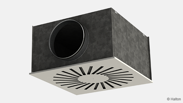
Halton Pop PLN is a high-performance plenum designed to optimise the functionality of linear nozzle diffusers.
It ensures efficient, balanced airflow distribution for both supply and exhaust applications while facilitating easy installation, maintenance, and acoustic control.
- Optional sound attenuation with mineral wool or polyester fibre
- Detachable module for airflow measurement and adjustment

Overview
Halton Pop PLN is a plenum for nozzle diffuser that connects the unit to ductwork for both supply and exhaust air applications, ensuring balanced airflow and optimal diffuser performance. It provides access for duct cleaning and can incorporate sound-attenuating materials, such as mineral wool or polyester fibre, to reduce noise levels.
Application areas
- Office buildings and workspaces
- Laboratories and health care facilities
- Commercial and public spaces
Product models and accessories
- Model with sound attenuation with mineral wool or polyester fibre
- A detachable airflow rate measurement and adjustment module.
Operating principle

Inside the balancing plenum, duct pressure and air velocity are reduced. Air is then supplied into the space through the diffuser, improving air distribution quality. When equipped with a measurement and adjustment module, the volume flow rate can be adjusted accurately.
Features and options
| Category | Feature (Order code) | Option (Order code) | Description |
|---|---|---|---|
| Sound attenuator | Sound attenuation material (IN) | NA | No attenuation material |
| 2W | Mineral wool on 2 sides | ||
| 5W | Mineral wool on 5 sides | ||
| 2P | Polyester fibre on 2 sides | ||
| 5P | Polyester fibre on 5 sides | ||
| Spigot | Spigot type (SG) | G | Spigot with gasket |
| W | Spigot without gasket | ||
| MSM | Airflow measurement and adjustment module (OM) | NA | Not assigned |
| S | Supply (MSM module) |
Structure and materials

| No. | Part | Material | Description |
|---|---|---|---|
| 1 | Balancing plenum | Galvanised steel | – |
| 2 | Spigot | Galvanised steel | Spigot equipped with rubber gasket |
| 3 | Sound attenuation material | Mineral wool or polyester fibre | The mineral wool is fixed with nails |
Dimensions

| Slots | H | K | ØD |
|---|---|---|---|
| 2 | 275 | 171 | 125, 160 or 200 |
| 3 | 275 | 221 | 125, 160 or 200 |
Standard dimensions for nozzle diffusers
| Diffuser active length [mm] | L [mm] | L1 [mm] | Duct connections |
|---|---|---|---|
| 375 | 374 | 188 | 1 |
| 430 | 429 | 215 | 1 |
| 485 | 484 | 243 | 1 |
| 540 | 539 | 270 | 1 |
| 650 | 649 | 325 | 1 |
| 595 | 594 | 298 | 1 |
| 705 | 704 | 353 | 1 |
| 760 | 759 | 380 | 1 |
| 815 | 814 | 408 | 1 |
| 870 | 869 | 435 | 1 |
| 925 | 924 | 463 | 1 |
| 980 | 979 | 490 | 1 |
| 1035 | 1034 | 518 | 1 |
| 1145 | 1144 | 573 | 1 |
| 1190 | 1189 | 595 | 1 |
| 1200 | 1199 | 600 | 1 |
| 1255 | 1254 | 628 | 1 |
| 1310 | 1309 | 655 | 1 |
| 1365 | 1364 | 683 | 1 |
| 1420 | 1419 | 710 | 1 |
| 1475 | 1474 | 738 | 1 |
| 1530 | 1529 | 765 | 1 |
| 1585 | 1584 | 793 | 1 |
| 1640 | 1639 | 410 | 2 |
| 1695 | 1694 | 424 | 2 |
| 1750 | 1749 | 438 | 2 |
| 1805 | 1804 | 451 | 2 |
| 1860 | 1859 | 465 | 2 |
| 1915 | 1914 | 479 | 2 |
Specification
Function
- Includes an airflow measurement and adjustment module.
- Diffuser is detachable for access to the module inside the plenum.
- Reduces duct pressure and air velocity to supply air across the entire face area of the nozzle diffuser, improving air distribution quality.
Materials
- Plenum constructed from galvanised steel.
- Plenum comprises sound attenuation material made of mineral wool or polyester fibre.
Installation

| No. | Part |
|---|---|
| 1 | Plenum |
| 2 | Airflow measurement and adjustment module |
- Install the plenum into the suspended ceiling using M8 drop rods (not supplied).
- Connect the plenum to the ductwork via a spigot equipped with an integrated rubber gasket.
- When using a measurement and adjustment module, maintain a recommended safety distance upstream of at least 3D to ensure reliable airflow rate measurement.
Avoid excessive bending of the unit’s control spindle.
Commissioning
- For airflow adjustment and measurement, connect the diffuser to a plenum equipped with the MSM module.
- Determine the supply flow rate using the MSM module.
- Detach the nozzle diffuser and pass the tubes and control spindle through the diffuser.
- Reinstall the diffuser/exhaust unit after adjustments.
Measure the differential pressure using a manometer. The flow rate is calculated using the formula below:

| ∆Pm | Measured pressure [Pa] |
| k | k-factor given as a function of mounting and diameter |
| qv | Airflow rate [l/s] |
The k-factor for installations with different safety distances(D= duct diameter):
| Duct connection (NS) | k-factor of MSM adjuster, opening > 0 [l/s] | |
|---|---|---|
| >6D | min 3D | |
| 125 | 9.9 | 12.6 |
| 160 | 19 | 22 |
| 200 | 49 | 32 |
Maintenance
- Remove the measurement and adjustment module by gently pulling the shaft (not the control spindle).
- Clean parts with a damp cloth. Do not immerse in water.
Reassemble by pushing the shaft back until the module meets the stopper.
Order code
PLN-S-L-D-N; AT-SG- OM- ZT
| Main options | |
|---|---|
| S = Number of rows | 2, 3 |
| L = Active length [mm] | 375, 430, 485, 540, 595, 650, 705, 760, 815, 870, 925, 980, 1035, 1190, 1145, 1200, 1255, 1310, 1365, 1420, 1475, 1530, 1585, 1640, 1695, 1750, 1805, 1860, 1915 |
| D = Duct connection size [mm] | 125, 160, 200 |
| N = Number of duct connections | 1, 2 |
| Other options and accessories | |
|---|---|
| AT = Sound attenuation material | |
| NA | Not assigned |
| 2W | 2 sides, mineral wool |
| 5W | 5 sides, mineral wool |
| 2P | 2 sides, polyester fibre |
| 5P | 5 sides, polyester fibre |
| SG = Spigot type | |
| G | With gasket |
| W | Without gasket |
| OM = Measurement / adjustment module | |
| NA | Not assigned |
| S | Supply (MSM adjuster) |
| ZT = Tailored product | |
| N | No |
| Y | Yes (ETO) |
| Order code example | |
|---|---|
| PLN-2-1255-160-2; AT=2W, SG=G, OM=N, ZT=N. |
Downloads
"*" indicates required fields
Halton APL – Jet air diffuser
product

Halton APS – Jet air diffuser
product
Halton BCF – Floor diffuser
product
Halton CAR – Conical diffuser
product
Halton DAC – Square diffuser
product
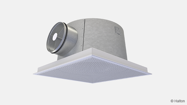
Halton DCS – Modular diffuser
product
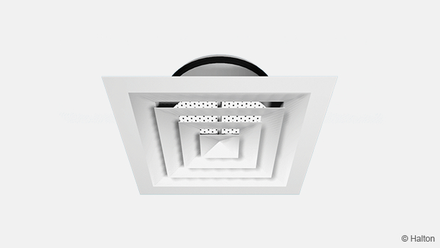
Halton DFA – Square conical diffuser
product

Halton DFB – Conical diffuser
product

Halton DFP – Modular ceiling diffuser
product
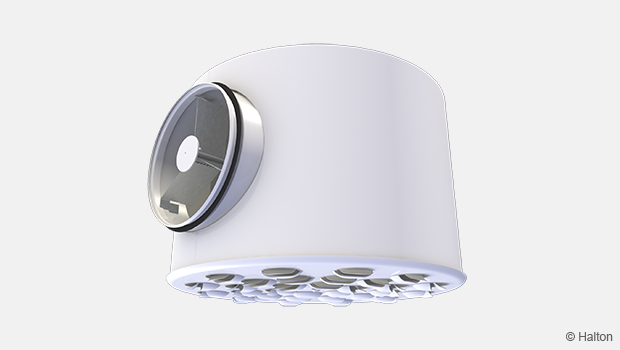
Halton DRV – Multi-nozzle terminal unit
product
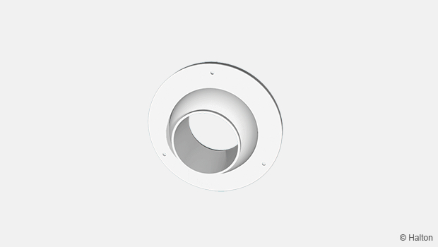
Halton IAO – Jet nozzle diffuser
product
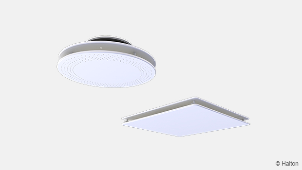
Halton Jaz JCC – Diffuser
product
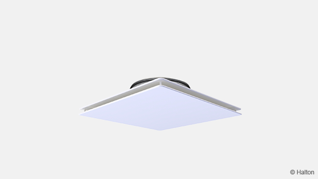
Halton Jaz JDA – Diffuser with side slot
product
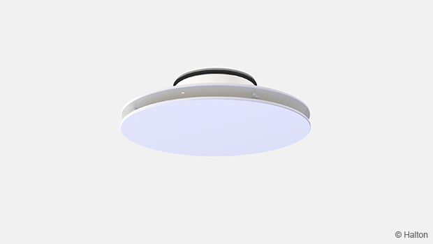
Halton Jaz JDB – Diffuser with side slot
product
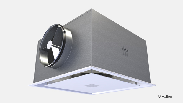
Halton Jaz JDS – Variable air volume diffuser unit (VAV)
product
Halton Jaz JMC – Nozzle diffuser
product
Halton Jaz JRC – Perforated diffuser
product
Halton Jaz JRP – Swirl diffuser
product
Halton Jaz JSC – Nozzle diffuser
product
Halton Jaz JTH – Swirl diffuser
product