Product / SCS
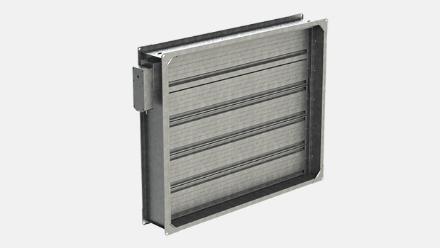
Halton Sec SCS – Smoke control damper (MAsingle, AAsingle)
This CE marked single compartment smoke control damper for automatically (AA) and manually (MA) activated systems is one of the narrowest in the market.
- Sizes from 200×200 up to 1250×1000 mm available
- Model with stainless steel (AISI 316L) material available
Overview
- CE marked according to the product standard EN 12101-8:2011
- Fire resistance class
- E600 120 (hodw-i↔o) S 1500C10000 AAsingle
- E600 120 (hodw-i↔o) S 1500C10000 MAsingle
- E600 120 (vew-i↔o) S 1500C10000 AAsingle
- E600 120 (vew-i↔o) S 1500C10000 MAsingle
- Certificate of constancy of performance 0809-CPR-1018
- Classification of casing leakage EN 1751 class C
- Manufacturing in accordance with the ISO 9001 quality standard.
- Third party certification product audit by Eurofins Expert Services Oy.
- Suitability for use in smoke extraction ducts with a maximum of 1500 Pa under pressure
- Suitability for use in ducts with a maximum air speed of 15 m/s.
- Suitability for rectangular smoke extraction ducts from size 200 mm x 200 mm to 1250 mm x 1000 mm.
Product models and accessories
- Suitable for the automatically activated fire alarm systems (AA)
- Suitable for the manual activated fire alarm systems (MA)
- Models equipped with electric actuator (no fuse, no spring return)
- Actuator with a visual position indicator
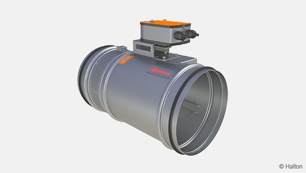
- Circular duct connections
- Modular damper casing extension for optional protecting mesh (L+210 mm)
- Model with stainless steel AISI 316 material also available
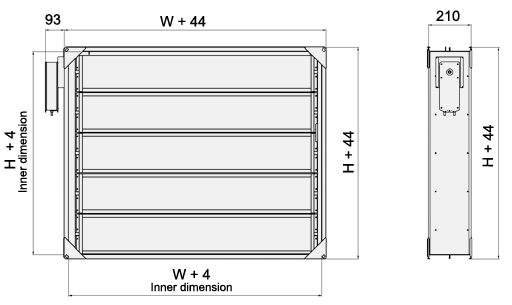
Dimensions
Rectangular connections (R)
| H/W [mm] |
200-1000 [mm] |
1050 [mm] |
1100 [mm] |
1150 [mm] |
1200 [mm] |
1250 [mm] |
| 200 | B | H | H | H | H | H |
| 300 | B | H | H | H | H | H |
| 350 | B | H | H | H | H | H |
| 400 | B | H | H | H | H | H |
| 450 | B | H | H | H | H | H |
| 500 | B | H | H | H | H | H |
| 550 | B | H | H | H | H | H |
| 600 | B | H | H | H | H | H |
| 650 | B | H | H | H | H | H |
| 700 | B | H | H | H | H | H |
| 750 | B | H | H | H | H | H |
| 800 | B | H | H | H | H | H |
| 850 | B | H | H | H | H | H |
| 900 | B | H | H | H | H | H |
| 950 | B | H | H | H | H | H |
| 1000 | B | H | H | H | H | H |
B Both horizontal and vertical blade direction allowed
H Horizontal blade direction only
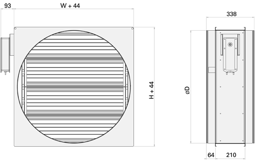
Circular connections (C)
| ØD [mm] |
W x H [mm] |
| 100 | 200×200 |
| 125 | 200×200 |
| 160 | 200×200 |
| 200 | 200×200 |
| 250 | 300×300 |
| 315 | 300×300 |
| 400 | 400×400 |
| 500 | 500×500 |
| 630 | 600×600 |
| 800 | 800×800 |
| 1000 | 1000×1000 |
Material
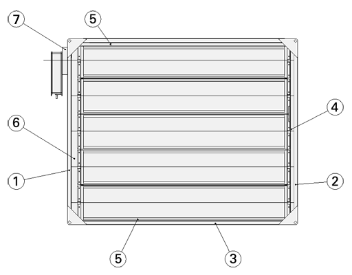
| Number | Part | Material | Note |
| 1, 2, 3 | Casing | Galvanised steel | Stainless steel available (EN 1.4404 / AISI 316L) |
| 4 | Blade stopper | Stainless steel (AISI 316) | – |
| 5 | Support beam, W sides | Stainless steel (AISI 316) | – |
| 6 | Bearing list, form actuator side |
Galvanised steel | Stainless steel available (EN 1.4404 / AISI 316L) |
| 7 | Actuator mounting bridge |
Galvanised steel | Stainless steel available (EN 1.4404 / AISI 316L) |
Accessories and actuators
| Accessory | Code | Description |
| Damper casing extension | CE | Length 210 mm, for structual thickness >200 mm |
| E600 120 (hodw-i↔o) S 1500C10000 AAsingle E600 120 (vew-i↔o) S 1500C10000 AAsingle |
A | Non insulated actuator |
| E600 120 (hodw)-i↔o) S 1500C10000 MAsingle E600 120 (vew-i↔o) S 1500C10000 MAsingle |
M | Actuator with heat insulated box |
Electric actuator options
Actuators do not have a fuse and are equipped with a limit switch.
R1 BEN24, operating voltage AC/DC 24 V, 15 Nm (H or W < 400 mm)
R2 BEN230, operating voltage AC 230 V, 15 Nm (H or W < 400 mm)
R3 BE24, operating voltage AC/DC 24 V, 40 Nm
R4 BE230, operating voltage AC 230 V, 40 Nm
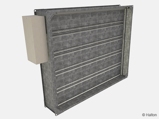
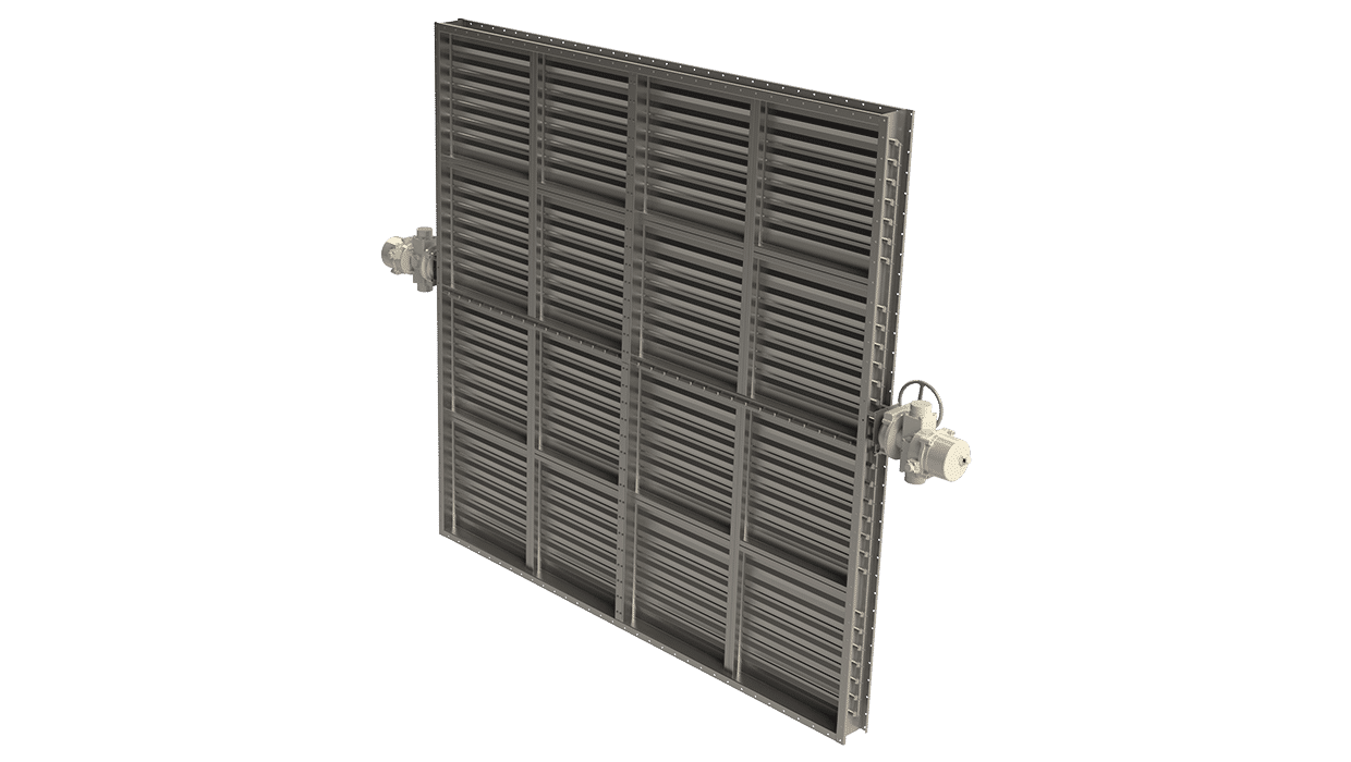
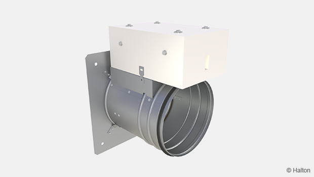
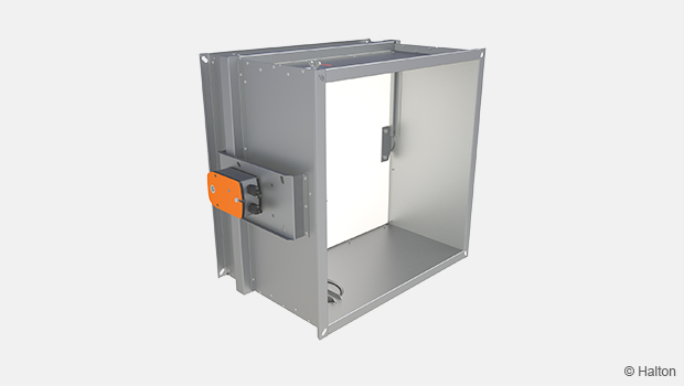
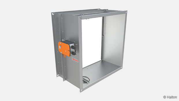
Fig.1. Halton Sec SCS, model M = Actuator with insulated box, for manual activation system.
Function
The Halton Sec SCS is a motorised rectangular smoke control damper that allows smoke to be extracted from the single compartment space by dedicated smoke extraction system.
The smoke damper is made of fireproof materials with incombustible glass fiber blade gaskets. They are preventing the air to infiltrate the extraction ducts to collect smoke from closed dampers.
The Halton Sec SCS smoke control damper shall be connected to the control and testing system delivered by Halton or to common building automation systems. The smoke control damper can be used in fully automatic (SCS/A) or manual activation (SCS/M) systems.
In case of fire sequence of operation is important, smoke extract fans should not be started before the smoke control dampers are opened.
Installation
Smoke control damper Halton Sec SCS can be installed on the certified single compartment ducts. Damper can be also installed on the wall or floor surface. The blade direction may be either horisontal or vertical.
The correct operation of the smoke control damper must be ensured before and after installation.
After fixing the smoke control damper check the diagonal dimension.
The damper should be cleaned after installation.
Detailed installation instructions, as well as an installer’s installation certificate form, are supplied with each product.
See also the section Downloads for detailed installation guidance.
Installation on the single compartment duct
All dampers are delivered with an installation flange, which is used to fasten the fire damper with screws to the surface of steel duct or to a connection.
The gap between the damper and the supporting structure is filled with fireproof seal rock wool or firestop mastic, after fixing of the damper.
When Halton Sec SCS is used as manual activated (MA) smoke control damper, connect the connection cables for electrical actuator inside of heat insulated box. Use nonflammable cables
Use M10 threaded rod for supporting the smoke control damper. See drawings below.
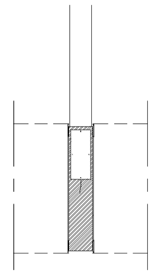
Installed to side of horisontal duct
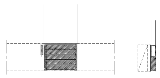
Installed to side of vertical duct
Note! Need to use CE marked smoke ducts.
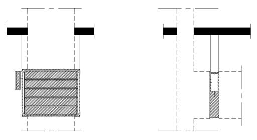
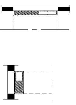
Installed on the top and bottom of duct
Installed in the horisontal duct
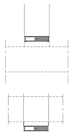
Installed on the wall or floor surface
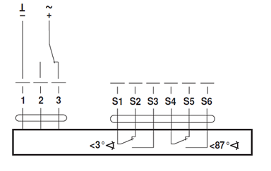
Electric actuator wiring diagram
Diagram below is used for actuators:
R1 BEN24 R3 BE24
R2 BEN230 R4 BE230
Servicing
No regular maintenance is required for the product.
Regular testing with the separate testing system is recommended twice a year.
Upon failure during testing of the smoke damper, a Halton representative shall be connected to ensure appropriate operation of the product
Specification
Multi-blade-type single zone smoke control damper Halton Sec SCS for rectangular and circular ducts with electric actuator and position indicator.
Damper has to fulfill the requirements from harmonized product standard EN 12101-8 and tested according to demands in standard EN 1366-10 and be labeled with CE Mark.
Damper has to be classified as:
E600 120(hodw-i↔o) S 1500C10000 AAsingle
E600 120(hodw-i↔o) S 1500C10000 MAsingle
E600 120 (vew-i↔o) S 1500C10000 AAsingle
E600 120 (vew-i↔o) S 1500C10000 MAsingle
The casing and blades of the smoke control damper shall be made of galvanised or stainless steel and the blade gaskets made of incombustible material.
The smoke control damper shall be installed horisontal and vertical position, CE marked, single compartment duct with incombustible sealing mass to ensure tightness of the connection
Order code
SCS-W-H; CM-MA-CT-SF-RE-AC-ZT
S = Type of connection
R Rectangular
C Circular
D = Connection size – if circular connection [mm]
100, 125, 160, 200, 250, 315, 400, 500, 630, 800, 1000
W = Width – if rectangular connection [mm]
200, +50, …, 1250
H = Height – if rectangular connection [mm]
200, 300, +50, …, 1000
Other options and accessories
CM = Model
A Actuator without heat insulated box (for automatic activation system)
M Actuator with heat insulated box (for manual activation system)
MA = Material
CS Galvanised Steel
AS Stainless steel (EN 1.4404/AISI 316L)
CT = Type of circular connection
D2 Circular connections on both sides
D1 Circular connection only on actuator side
SF = Flange option
NA Standard
L1 Standard + flange connection
L2 Flange connection on both sides
R2 Flange connection with holes
RE = Release type
R1 BEN24 (no fuse), 15 Nm (H or W < 400 mm)
R2 BEN230 (no fuse, 15 Nm (H or W < 400 mm)
R3 BE24 (no fuse), 40 Nm
R4 BE230 (no fuse), 40 Nm
AC = Accessories
CE Casing extension of 210 mm, for structural thickness > 200mm
ZT = Tailored product
N No
Y Yes (ETO)
Order code example
SCS/R-200-200 , CM=A, MA=CS, CT=D2, SF=NA, RE=B3, AC=NA, ZT=N
Downloads
-
Halton Sec SCS – Smoke control damper (MAsingle, AAsingle)
Data
en
-
Halton Sec SCS – Savunhallintapelti (MAsingle, AAsingle)
Data
fi
-
Halton Sec SCS – Rökkontrollspjäll (MAsingle, AAsingle)
Data
se
-
Halton SCS – huolto-ohje
Data
fi_FI -
Halton SCS – Installation Instructions and Proof of Installation
Data
en_GB -
Construction Product Regulation (CPR) – SCS
Data
en_GB -
Declaration of Performance (DoP) – Halton Sec SCS
Data
English (en) -
Halton SCS – asennusohjeet ja asennustodistus
Data
fi_FI -
Palo- ja savunhallintapeltien asennustodistus
Data
Suomi (fi)
"*" indicates required fields
CFD-02TM – High temperature tunnel damper
product
Halton Sec SCS – Smoke control damper (MAsingle, AAsingle)
product
Halton Sec SFC – Smoke control damper (MAsingle)
product
Halton Sec SFR – Smoke control damper (AAsingle)
product
Halton Sec SMR – Smoke control damper (MAmulti, AAmulti)
product
Halton Sec SSC – Smoke control damper (AAmulti)
product
Halton Sec SSR – Smoke control damper (AAmulti)
product