Product / CSW
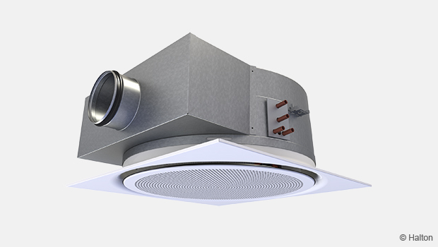
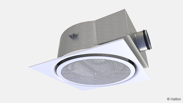
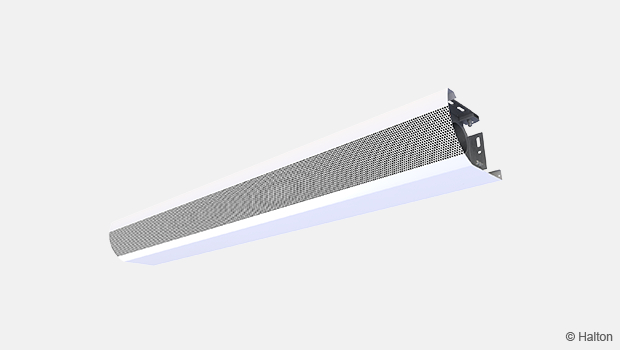
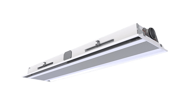
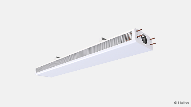
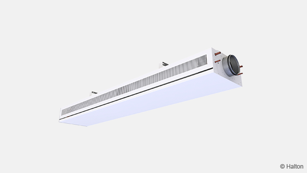
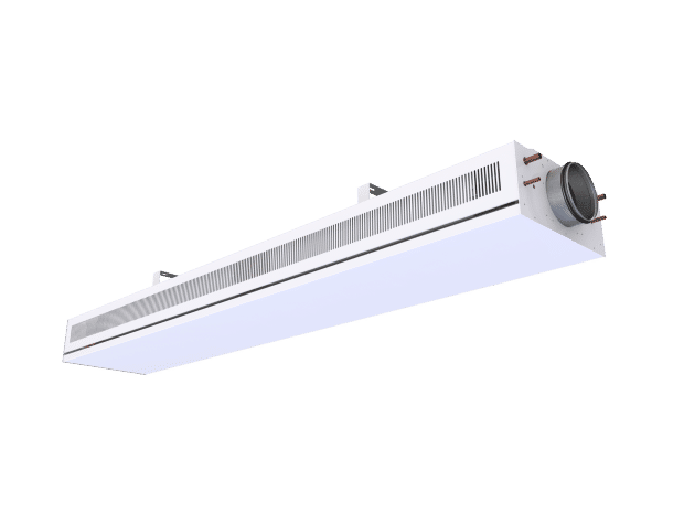
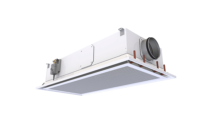
Halton CSW – Swirl comfort unit
This aesthetic chilled beam creates draught free environments and is suitable for many different styles of suspended ceiling designs.
- A combined cooling, heating, and supply-air unit for flush installation within a suspended ceiling.
- An ideal solution for applications in which high-quality environmental conditions and individual room control are appreciated.
Overview
The swirl comfort unit is a compact air-conditioning unit providing swirl jet air supply.
- A combined cooling, heating, and supply-air unit for flush installation within a suspended ceiling.
- An ideal solution for applications in which high-quality environmental conditions and individual room control are appreciated.
- A high-induction swirl jet to ensure efficient mixing and fast air-velocity decay.
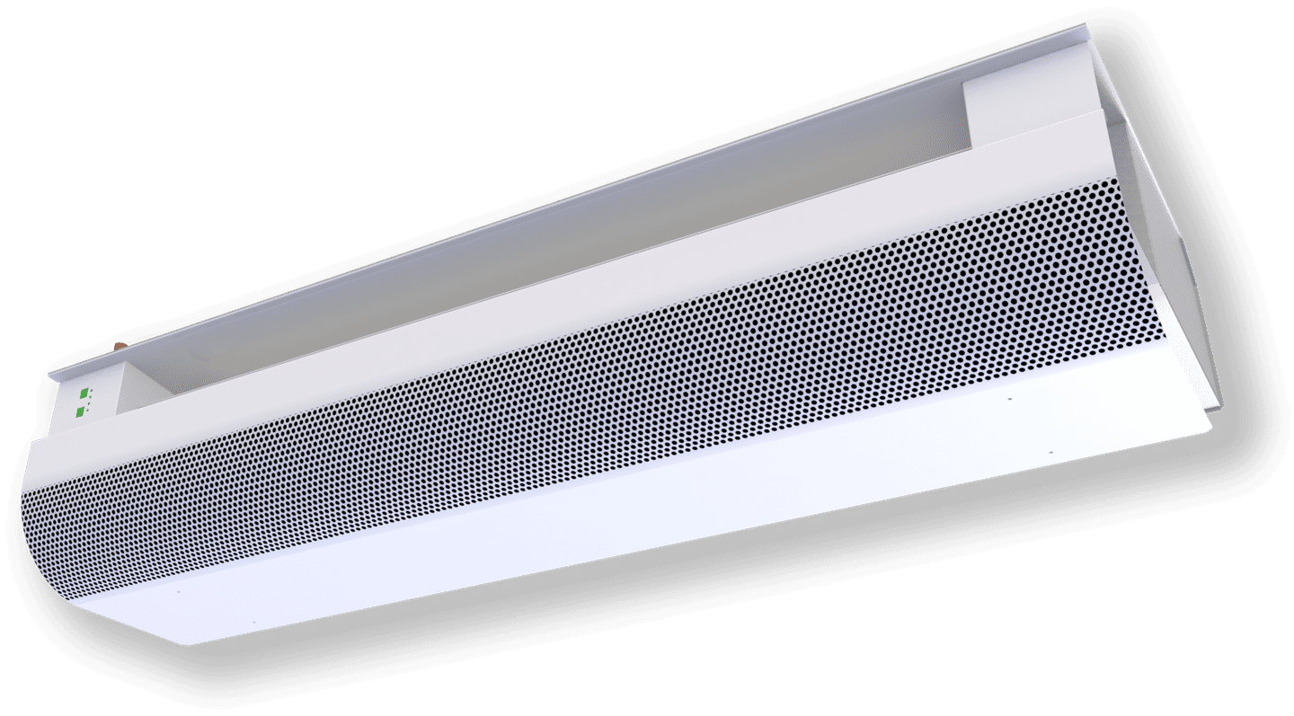
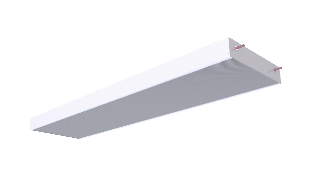
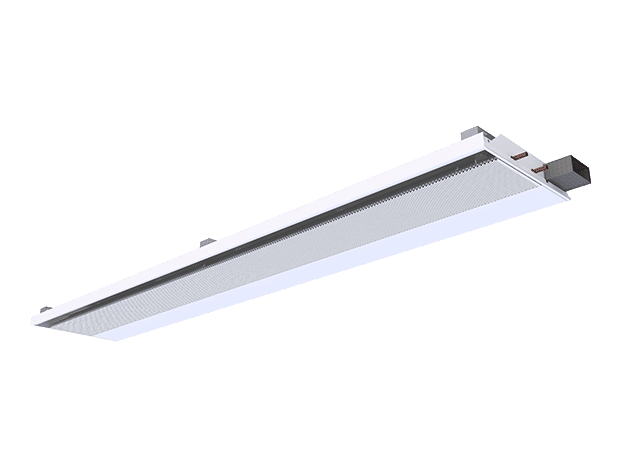
- A product range comprising the following units, all with a look matching that of the swirl comfort unit: supply-air diffuser, exhaust unit, variable airflow swirl comfort unit, and variable airflow exhaust air unit.
- Airflow rate that can be adjusted over a wide range by opening or closing of nozzles (the units have two sets of nozzles, of different sizes, and the nozzle pattern is radial 360º).
- No need for special tools to open/close nozzles.
- Typical applications that include small office rooms, landscape offices, team rooms, patient care rooms, lobbies, and relaxation and isolation rooms, with the unit especially well-suited to internal zones of office buildings.
- Modular construction ceiling sizes: 600 x 600 and 675 x 675 mm.
- Enhanced life-cycle performance with low airflow and waterflow rates.
- Individually adjustable velocity conditions with Halton Induction Control.
Halton chilled beams are certified by Eurovent Certita.

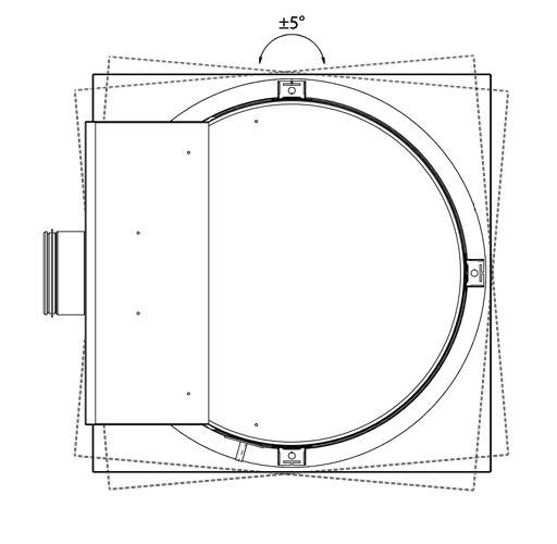
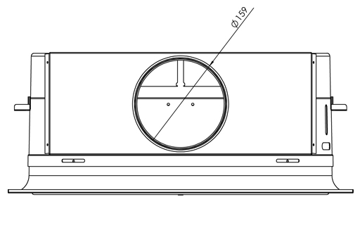
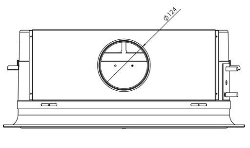
Dimensions and weight
Location of the water pipe & air duct connections
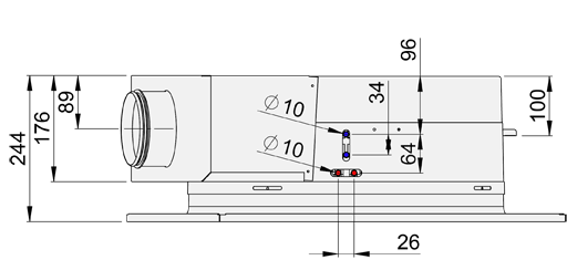
Threaded drop rods locations
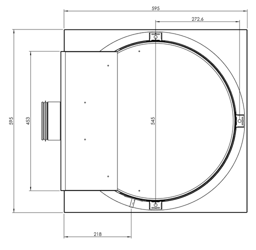
Front panel frame alignment
Exhaust model duct connection, size and location
Supply model duct connection, size and location
Weight
| Water excluded (kg/unit) |
Water included (kg/unit) |
| 17,8 | 18,3 |
Materials
| Part | Material | Finishing | Note |
| Front panel | Pre-painted galvanised steel |
Epoxy-painted, white (RAL 9003, 20% gloss) |
Special colours available, polyester-epoxy -painted |
| Front panel frame | Pre-painted galvanised steel |
Epoxy-painted, white (RAL 9003, 20% gloss) |
Special colours available, polyester-epoxy -painted |
| Casing | Galvanised steel | – | – |
| Nozzles | Plastic | – | – |
| Supply air plenum | Galvanised steel | – | – |
| Brackets | Galvanised steel | – | – |
| Coil pipes | Copper | – | – |
| Coil fins | Aluminium | – | – |
Accessories
Harmonised appearance of units for different functions:
Room air-conditioning unit
- Air–water cooling, and additionally ventilation: CSW/S-C, AQ = A or R
- Air–water cooling and heating, and additionally ventilation: CSW/S-H ,AQ = A or R
- Availability also in corresponding models with variable air-flow rate for demand-controlled ventilation in constant-pressure ductwork zone applications: CSW/S-C, AQ = B and CSW/S-H, AQ = B
VAV beam operation
- Individually adjustable supply-air-flow rate for changes in space layout by means of Halton Air Quality (HAQ) control
- Demand-based control of supply-air flow, for efficient use of energy in constant-pressure ductwork zone applications
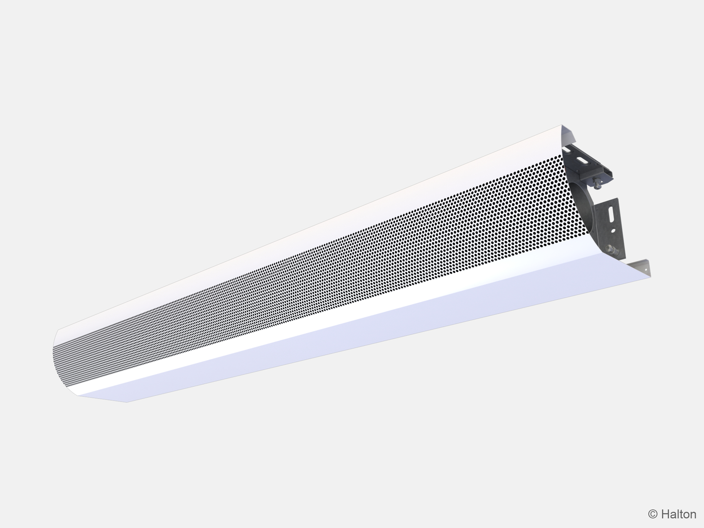
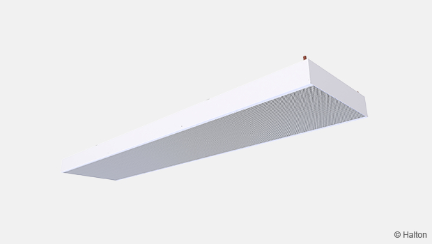
High-induction diffuser
- All-air room air conditioning and ventilation with constant air flow: CSW/S-N, AQ = A or R
- All-air room air conditioning and ventilation with variable air flow: CSW/S-N, AQ = B
- High-induction diffuser to provide high comfort with cold supply air
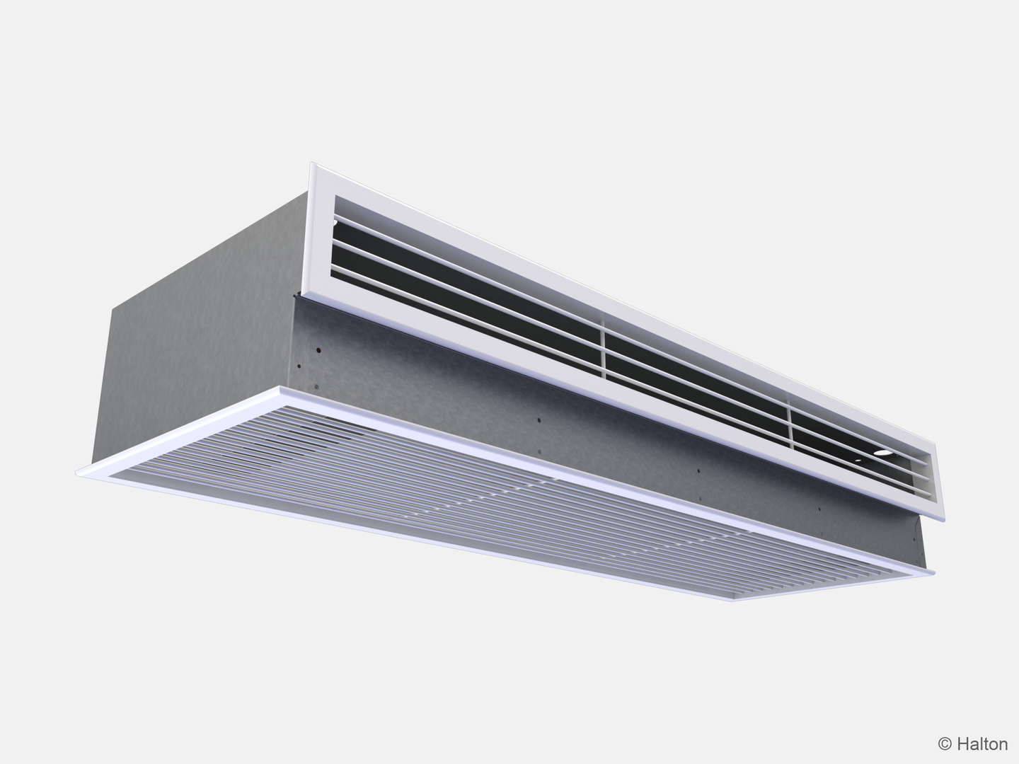
Exhaust unit
- Adjustable constant air flow: CSW/E, EQ = A
- Variable air-flow rate for demand-controlled ventilation in constant-pressure ductwork zone applications: CSW/E, EQ = B
- Easy and fast setting and adjustment of minimum and maximum values, integrated into the unit
- The same appearance as other options in the CSW range
Options for integration into various ceiling module sizes and ceiling types
- T-profile 600 x 600 mm
- T-profile 675 x 675 mm
Note: Please contact sales for other options.
Cooling water pipe connections are Cu10 with a wall thickness of 0.9–1.0 mm, fulfilling the requirements of European standard EN 1057:1996.
The maximum chilled-water circuit operating pressure is 1.0 MPa.
The supply-air duct connection diameter is 125 mm. With exhaust model connection diameter is 160mm.
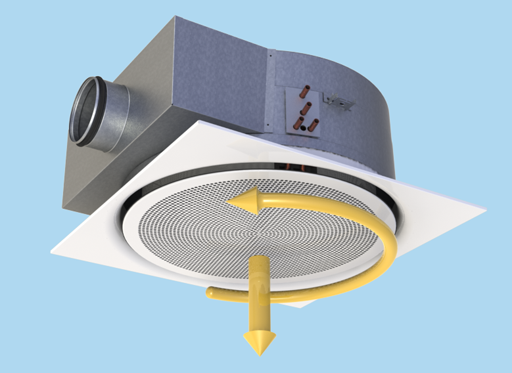
Operating principle
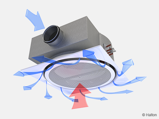
The Halton CSW swirl comfort unit is designed to be installed flush with a suspended ceiling.
The primary supply air enters the plenum of the swirl comfort unit, from which it is diffused into the room with a swirl effect through nozzles and supply slots at the bottom of the swirl comfort unit. Nozzles are in a circle supplying air 360º radially. The supply air nozzle jets efficiently induce ambient room air. Induced air flows through the heat exchanger, where it cools. The supply air jet is supplied from the nozzles, creating swirl functioning. Some of the nozzles are openable, to enable different supply airflow rates.
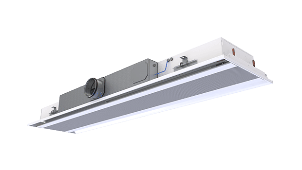
The swirl comfort units and high-induction diffuser can be used in constant or variable airflow applications.
In variable airflow operation mode, the air flow is controlled by means of an integrated motorised Halton Air Quality control damper, with either room temperature or CO2 content as the ventilation demand indicator. Supply air supplied by the HAQ damper is mixed with the induction air at high efficiency.
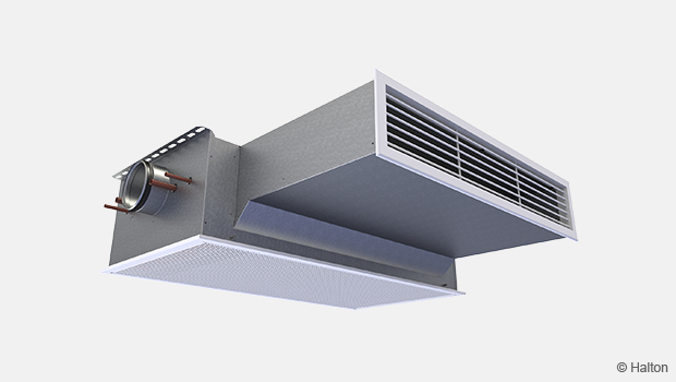
It is also possible to use a Halton CSW unit for exhaust. The Halton CSW exhaust unit has integrated airflow adjustment dampers. Air flow can be adjusted later also, with ease – just open the front panel and adjust the damper position. An actuator can also be incorporated, to enable continuous control of the air-flow rate. It is also possible to install the motorised version afterwards.
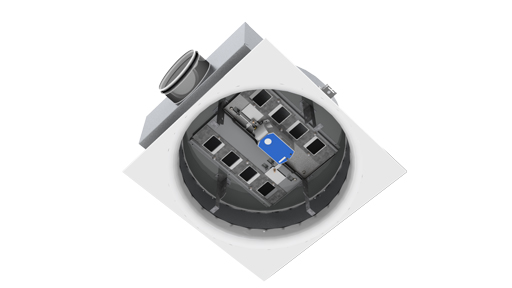
Induction control in the occupied zone
Halton Induction Control is used for adjusting room air velocity conditions either when room layout is changed (e.g., in cases where the partition wall is located near the chilled beam) or when local, individual velocity conditions need to be altered. Induction adjustment has an impact on the induced room airflow through the heat exchanger, and therefore it either increases or decreases both the velocities in the occupied zone and the cooling capacity of the comfort unit.
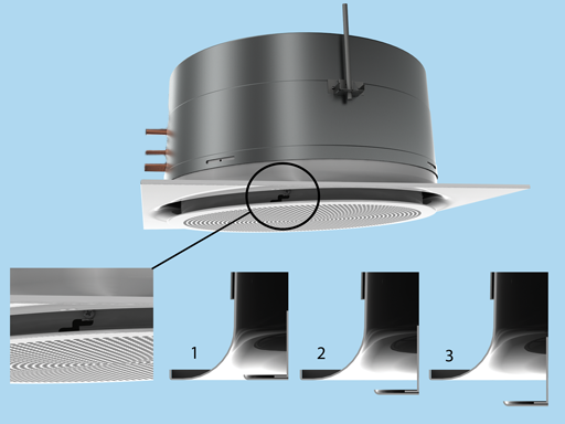
Pos.1 = Flush Pos. 2 = Enhanced Pos.3 = Boost.
Halton Induction Control uses manual velocity adjustment with three settings.
Control of airflow rate
The supply airflow of the swirl comfort unit nozzle jets depends on the static chamber pressure, which can be adjusted by means of a separate air-flow adjustment damper, for example.
Halton Air Quality control is an option for adjusting and/or controlling the rate of outdoor air flow in a room space. The air-flow rate is dependent on the opening position of the control damper and the static chamber pressure.
Airflow adjustment is needed when the use of the space changes and there is need to adapt the supply-air flows. Air-flow rate can also be automatically adjusted to demand via a motorised control damper. When there is a need for demand-based ventilation, motorised HAQ can be used for adjusting air flow in VAV operation.
A swirl comfort unit equipped with HAQ manual air-flow rate adjustment can be retrofitted for motorised operation for demand-based ventilation.
It is recommended that swirl comfort units for demand-based air flow be connected to a constant‑pressure ductwork zone when
- the HAQ adjustment has no impact on nozzle jet airflow
- the HAQ airflow control has no significant impact on ductwork pressure conditions and, respectively, on airflow rates of other swirl comfort units in the relevant ductwork zone
The appearance of different units with constant, adjustable, or variable air flow is identical.
The Halton Air Quality control unit’s position and the selection of swirl comfort unit nozzle size allow adjustment of the primary air-flow rate in the space. The separate air-flow-adjustment damper installed in the duct branch is used for balancing the air flows in the ductwork. When a motorised air quality control (HAQ) unit is used, the maximum and minimum air flow are adjusted with the stroke-limiters of the damper.
The primary air-flow rate of each beam is adjusted by means of the Halton Air Quality control unit during installation and commissioning.
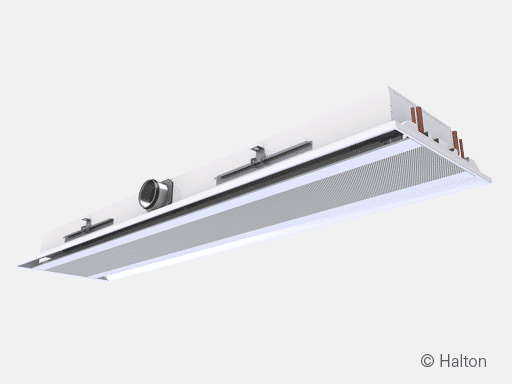
Exhaust model for constant and variable airflow
The Halton CSW exhaust model can be used for constant- or variable-flow exhaust applications.
The exhaust version is equipped with a built-in damper for easy adjustment of airflow rates to meet the flow demands as they change during the building’s service life.
In variable airflow applications, the exhaust damper is equipped with an actuator enabling control on the basis of the required exhaust‑air flow. Minimum and maximum air-flow rates can be set for different demands at any point in the building’s service life without any special tools, just by changing the position of stroke-limiters.
The appearance of both exhaust-air models is the same as that of supply-air diffuser units.
Air quality and temperature control
The cooling and heating capacities of the swirl comfort unit are controlled by regulation of the water-flow rate on the basis of the control signal of the room temperature controller.
Air quality control for a room space can be arranged via, for example, a CO2 sensor when room airtemperature is controlled separately through regulation of water flow. Alternatively, a temperature sensor can be used for air quality control, with the air flow modulated in the first sequence;, if the temperature exceeds that set, the water valve starts to open in the second sequence.
For heating mode, it is recommended that the temperature difference between jet outlet and room air be no greater than 3 °C. The inlet water temperature of the heat exchanger should not be higher than 35 °C. Optimal heating performance requires an appropriate primary air-flow rate, so the air-handling unit operates during heating season to ensure appropriate heating performance.
Installation
The Halton CSW swirl comfort unit is suitable for ceiling mounting flexibly in different positioning patterns in the room space. Air and water connections can be connected from any of four directions.
The variable airflow model is equipped with a motorised HAQ unit:
- Power supply: 24 VAC
- Control signal: 0 to 10 VDC
Each swirl comfort model is equipped with three brackets attached to the casing of the unit. The unit can be attached directly to the ceiling surface (H1 = 241 mm) or suspended by means of threaded drop rods (8 mm). Install the main pipelines of the chilled-water circuit above the level of the swirl comfort unit, in order to enable venting of the pipework.
Commissioning
Cooling
The recommended chilled-water mass flow rate for Halton CSW is 0.02 to 0.06 kg/s, resulting in a temperature increase of 1 to 4 °C in the heat exchanger. For avoiding condensation, the recommended inlet water temperature of the heat exchanger is 14 to 16 °C.
Balancing and control of water flow
Balance the water-flow rates of the swirl comfort unit by using adjustment valves, ideally for installation on the outlet side of the chilled-water loops. The cooling capacity of the swirl comfort unit is controlled by regulation of the water mass flow rate. The water mass flow rate can be controlled by means of an ON/OFF valve or a two- or three-way proportional valve.
Adjustment of supply airflow rate
Connect a manometer at the measurement tap, and measure the static pressure in the swirl comfort unit. The air-flow rate is calculated according to the formula below.
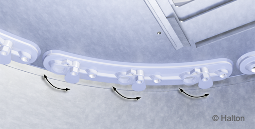
Nozzle jet air-flow rate (qv)
| N | Number of opened big nozzles |
| ∆pm | Measured static chamber pressure [Pa] |
| (l/s) | (m3/h) | |
| K1 | 0.73 | 2.63 |
| K2 | 0.097 | 0.35 |
Air quality control diffuser airflow rate (qv2)
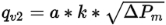
| a | HAQ unit position |
| ∆pm | Measured static chamber pressure [Pa] |
| k (l/s) | k (m3/h) |
| 0.08 | 0.29 |
Total airflow rate, qv
qv = qv1 + qv2
| qv | Total airflow rate, l/s or m3/h |
| qv1 | Nozzle jet airflow rate, l/s or m3/h |
| qv2 | Air quality control diffuser airflow rate, l/s or m3/h |
Adjustment of exhaust airflow
Connect a manometer to the measurement tap, and measure the static pressure in the swirl comfort unit. The air-flow rate is calculated according to the formula below.
Total air-flow rate, qv
![]()
| a1 | Position of HAQ unit 1 |
| a2 | Position of HAQ unit 2 |
| ΔPm | Measured static chamber pressure [Pa] |
| k (l/s) | k (m3/h) |
| 0.16 | 0.59 |
Adjustment of the airflow in constant-air-flow applications, for Halton CSW, both supply and exhaust
Determine the position, in millimetres, of the HAQ unit that corresponds to the air-flow rate at the actual chamber pressure level.
Adjustment of HAQ is done manually with the aid of the position scale by adjusting the opening of the unit. It is possible to verify the opening, in millimetres, from the position scale.
To ensure accurate adjustment, it is recommended to adjust HAQ position and at the same time read the target chamber pressure by using the manometer.
It is also possible to remove the HAQ unit from the frame, by opening the two knurled-head adjustment screws (4).
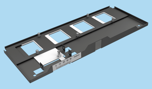
Manual HAQ damper unit for constant-air-flow adjustment.
Adjustement of the flow range in variable-air-flow applications, both supply and exhaust
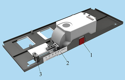
Variable flow adjustments of the HAQ damper unit.
| No. | Description |
| 1 | Release of the actuator |
| 2 | Limiter of the maximum opening |
| 3 | Limiter of the minimum opening |
Switch off the power supply to the actuator.
Disengage the actuator gear for manual override position by releasing the knob (1).
Determine the maximum and minimum positions, in millimetres, that correspond to maximum and minimum air-flow rates at the actual chamber pressure level. The maximum and minimum positions are adjusted with two hexagonal socket set screws (2, 3). It is possible to verify the opening from the position scale (in millimetres).
Switch on the power supply of the actuator (24 VAC). The actuator calibrates the minimum and maximum positions automatically according to the limits set.
The actuator can be controlled from this point on via a 0 to 10 VDC control signal (0 VDC = min. position, 10 VDC = max. position).
It is also possible to remove the HAQ unit from the frame for adjustment, by opening the two knurled-head screws (4).
Exhaust models of Halton CSW unit are equipped with two adjustable dampers. In variable-flow operation, the second of these is equipped with an actuator, which controls the damper position.
Maintenance
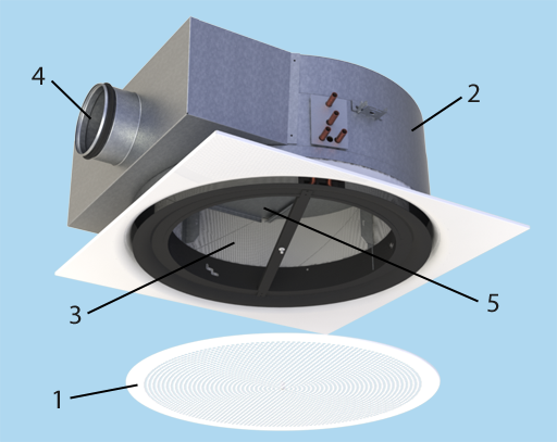
| No. | Description |
| 1 | Front panel |
| 2 | Casing; plenum box |
| 3 | Heat exchanger |
| 4 | Supply air connection |
| 5 | Access panel |
Open the front panel (1) of the supply-air plenum in order to gain access to the ductwork and to the heat exchanger (3). Clean the supply-air plenum and finned coils of the heat exchanger with a vacuum cleaner, taking care not to damage the finned coils.
Clean the front panel, using a damp cloth.
Check at regular intervals that the chilled-water flow control valve is working.
The access panel enables access for duct-cleaning. Unscrew the screws of the access panel to open it.
Specification
Function
- The comfort unit has an integral re-circulation air path through the perforated front panel. The induced room airflow is manually adjustable via three settings without affecting the primary air supply flow rate.
- The comfort unit’s primary airflow rate is adjustable by opening and closing the nozzles.
- The comfort unit has as options a manual airflow adjustment damper and a motorised airflow control damper unit for increasing the supply airflow rate, in addition to the nozzle airflow. The manual damper unit can be easily replaced with a motorised unit.
- Control of the outdoor air flow rate has no effect on coil cooling capacity. The comfort with adjustable airflow has only one duct connection.
Materials
- The casing is made of galvanised steel plate.
- All visible parts are white, painted to RAL 9003 (20% gloss).
- All pipes are manufactured from copper, and connection pipes with a wall thickness of 0.9–1.0 mm.
- The fins are manufactured from aluminium. All joints are soldered and factory pressure-tested.
Structure
- The product has an option for exhaust operation equipped with either manual or motorised control. Adjusting airflow is easily implemented without removing ceiling panels or using external access panels.
- The units are available for air, water and all-air room air conditioning. The appearance of the comfort unit, supply air diffuser, and exhaust unit is the same.
- The front panel is openable to allow general maintenance and cleaning.
- The air supply to the room is radially distributed over 360º.
- The comfort unit has an inlet duct diameter of 125 mm.
- The maximum operation pressure of the pipework is 1.0 MPa.
- The comfort unit has a measurement tap for airflow measurement.
- Adjustment is effected by opening of the product, with no need to remove ceiling panels or use external access panels.
Packaging and transport
- Each comfort unit is protected by removable plastic film and individually packed in a plastic bag.
- The duct connection and pipe ends remain sealed during transport.
- The comfort units are identified by a serial number printed on labels attached to both the comfort unit and its plastic packaging.
Order code
CSW-S-IN-TC; AQ-EQ-CO-ZT
| Main options | |
| S = Model | |
| S | Supply device |
| E | Exhaust device |
| IN = Ceiling type installation option | |
| NA | Standard for T-profile 600 |
| T2 | T-profile 675 |
| TC = Cooling / Heating functions (Coil type) | |
| C | Cooling |
| H | Cooling and heating |
| N | Without coil |
| Other options and accessories | |
| AQ = Air quality control | |
| A | Manual |
| B | Motorised |
| R | Retrofit |
| EQ = Exhaust control | |
| A | Manual |
| B | Motorised |
| CO = Colour | |
| SW | Signal white (RAL9003) |
| X | Special colour (RALxxxx) |
| ZT = Tailored product | |
| N | No |
| Y | Yes (ETO) |
Order code example
CSW-S-NA-C2; AQ=A, EQ=NA, CO=SW, ZT=N
References

Fig.1. Meeting room in Helsinki, Finland

Fig.2. Meeting room in Helsinki, Finland
Downloads
"*" indicates required fields
Halton CaBeam – Chilled beam for exposed wall installation
product
Halton CaBeam – Chilled beam for integrated installation
product
Halton CaBeam – Chilled beam for recessed installation
product
Halton CBH – Chilled beam
product
Halton CHB – Chilled beam
product
Halton CPA – Passive chilled beam
product
Halton CSW – Swirl comfort unit
product
Halton Rex R6W – Variable air volume chilled beam (VAV)
product
Halton Rex RE6 – Chilled beam
product
Halton Rex REE – Chilled beam
product
Halton Rex REO – Chilled beam (VAV)
product
Halton Rex REW – VAV chilled beam
product
Halton Rex RXP – Chilled beam (CAV/VAV)
product

Halton Vita VPR – Hygienic chilled beam
product
NEW! Halton CaBeam REC – For Passenger and Crew Cabins
product
NEW! Halton Rex REP – Passive chilled beam
product
NEW! Halton Rex RSI – Slim induction unit
product