Product / ESR
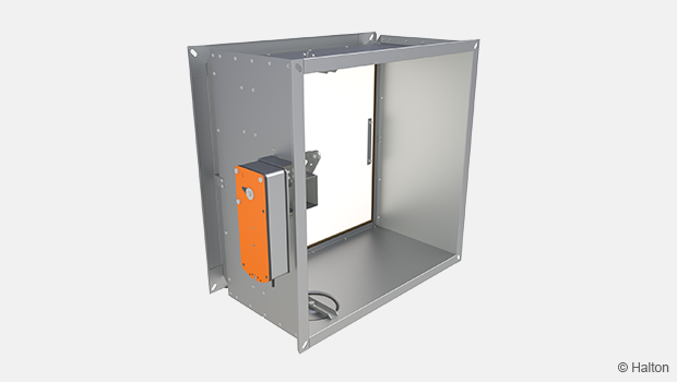
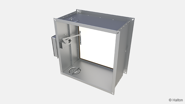
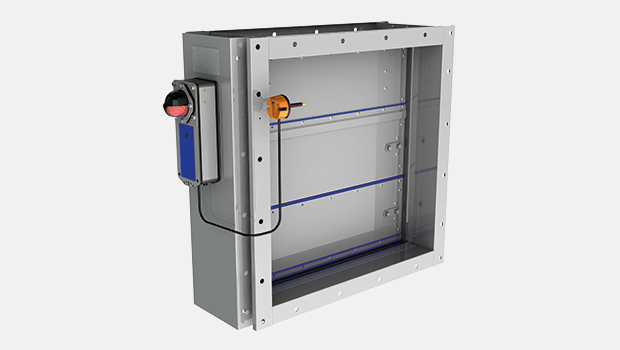
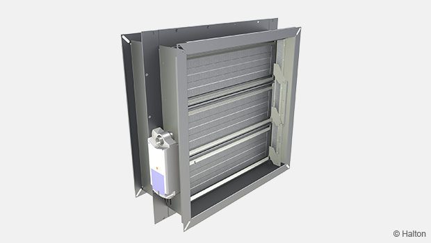
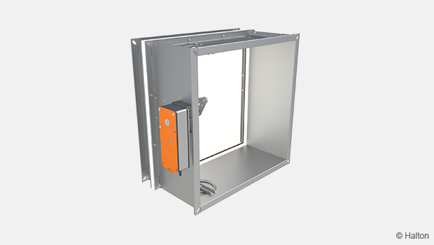
Halton Exe ESR – Fire damper (EI 120 S)
This CE marked fire damper needs minimum free space around its body in case of installation. Installation option up to 1.0 meter away from the structure (up to EI 90 S) has been certified. Fire resistance class is provided up to EI 120 S requirements.
- Suitable for vertical (wall) and horizontal (ceiling/floor) installation
- Frame construction is galvanised steel as standard. Stainless steel option available on request.
Overview
This fire damper model needs minimum free space around its body in case of installation. It is suitable for both vertical and horizontal installation in concrete, masonry or lightweight structures. Installation option up to 1.0 meter away from the structure (up to EI 90 S) has been certified. Fire resistance class is provided up to EI 120 S requirements.
Features
- Supplied with electrical spring return actuator (24 V or 230 V), or mechanical spring release (failsafe)
- Sizes from 200×200 mm up to 1000×500 mm are available
- Maximum air velocity through fire damper in open position is 12 m/s
- Suitable for use in ducts with a maximum pressure difference of 1200 Pa
- Frame construction is galvanised steel as standard. Stainless steel option available on request.
- No spare parts or additional installation frames needed for basic installation method
Installation options
- Suitable for vertical (wall) and horizontal (ceiling/floor) installation
- Vertical installation (wall) with spindle of the blade in either vertical or horizontal position
- Can be installed up to 1.0 m away from the separate element (up to EI 90 S)
- CE marked for installation in concrete, masonry or lightweight structures with fire resistance classes of EI 120, EI 90 or EI 60
- Limit switch(es) available as an accessory for mechanical spring release (failsafe)
Standards
This product complies with the following standards:
- CE certified according to product standard EN 15650
- Fire classification according to EN 13501-3+A1 standard
EI 120 (ve hoi↔o) S, EI 90 (ve ho i↔o) S, EI 60 (ve ho i↔o) S - Fire testing according to EN 1366-2
- CE certificate of Constancy of Performance 1391-CPR-2018/0202
- Declaration of Performance No:10034-ESR-2019/01/01
- Fire damper internal leakage is class 2 according to EN 1751
- Damper casing tightness class C according to EN 1751
- Corrosion resistance: Salt mist test EN 60068-2-52
Dimensions and weight
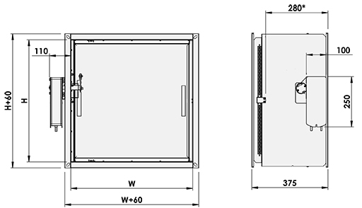
| W = Width [mm] | H = Height [mm] |
| 200, 250, 300, 350, 400, 450, 500, 550, 600, 700, +100, … 1000 | 200, 250, 300, 350, 400, 450, 500, 550, 600, 700, 800 |
* Space reservation for fire damper
Overlap of blade (mm
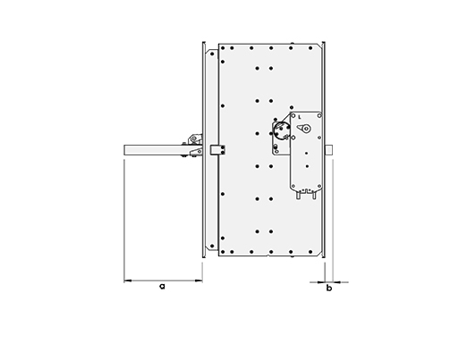
| width x height | a | b | width x height | a | b | width x height | a | b |
| 200 x 200 | 6,5 | 40 | 400 x 200 | 40 | – | 600 x 200 | 40 | – |
| 200 x 250 | 7,5 | 65 | 400 x 250 | 65 | – | 600 x 250 | 65 | – |
| 200 x 300 | 8,0 | 90 | 400 x 300 | 90 | – | 600 x 300 | 90 | – |
| 200 x 350 | 117,5 | – | 400 x 350 | 117,5 | – | 600 x 350 | 117,5 | – |
| 200 x 400 | 140 | – | 400 x 400 | 140 | – | 600 x 400 | 140 | – |
| 200 x 450 | 165 | – | 400 x 450 | 165 | – | 600 x 450 | 165 | – |
| 200 x 500 | 190 | – | 400 x 500 | 190 | – | 600 x 500 | 190 | – |
| 200 x 550 | 215 | – | 400 x 550 | 215 | – | 600 x 550 | 215 | – |
| 200 x 600 | 240 | – | 400 x 600 | 240 | – | 600 x 600 | 240 | – |
| 200 x 700 | 290 | – | 400 x 700 | 290 | – | 600 x 700 | 290 | – |
| 200 x 800 | 340 | 40 | 400 x 800 | 340 | 40 | 700 x 200 | 40 | – |
| 250 x 200 | 40 | – | 450 x 200 | 40 | – | 700 x 250 | 65 | – |
| 250 x 250 | 65 | – | 450 x 250 | 65 | – | 700 x 300 | 90 | – |
| 250 x 300 | 90 | – | 450 x 300 | 90 | – | 700 x 350 | 117,5 | – |
| 250 x 350 | 117,5 | – | 450 x 350 | 117,5 | – | 700 x 400 | 140 | – |
| 250 x 400 | 140 | – | 450 x 400 | 140 | – | 700 x 450 | 165 | – |
| 250 x 450 | 165 | – | 450 x 450 | 165 | – | 700 x 500 | 190 | – |
| 250 x 500 | 190 | – | 450 x 500 | 190 | – | 700 x 550 | 215 | – |
| 250 x 550 | 215 | – | 450 x 550 | 215 | – | 700 x 600 | 240 | – |
| 250 x 600 | 240 | – | 450 x 600 | 240 | – | 800 x 200 | 40 | – |
| 250 x 700 | 290 | – | 450 x 700 | 290 | – | 800 x 250 | 65 | – |
| 250 x 800 | 340 | 40 | 450 x 800 | 340 | 40 | 800 x 300 | 90 | – |
| 300 x 200 | 40 | – | 500 x 200 | 40 | – | 800 x 350 | 117,5 | – |
| 300 x 250 | 65 | – | 500 x 250 | 65 | – | 800 x 400 | 140 | – |
| 300 x 300 | 90 | – | 500 x 300 | 90 | – | 800 x 450 | 165 | – |
| 300 x 350 | 117,5 | – | 500 x 350 | 117,5 | – | 800 x 500 | 190 | – |
| 300 x 400 | 140 | – | 500 x 400 | 140 | – | 800 x 550 | 215 | – |
| 300 x 450 | 165 | – | 500 x 450 | 165 | – | 800 x 600 | 240 | – |
| 300 x 500 | 190 | – | 500 x 500 | 190 | – | 900 x 200 | 40 | – |
| 300 x 550 | 215 | – | 500 x 550 | 215 | – | 900 x 250 | 65 | – |
| 300 x 600 | 240 | – | 500 x 600 | 240 | – | 900 x 300 | 90 | – |
| 300 x 700 | 290 | – | 500 x 700 | 290 | – | 900 x 350 | 117,5 | – |
| 300 x 800 | 340 | 40 | 500 x 800 | 340 | 40 | 900 x 400 | 140 | – |
| 350 x 200 | 40 | – | 550 x 200 | 40 | – | 900 x 450 | 165 | – |
| 350 x 250 | 65 | – | 550 x 250 | 65 | – | 900 x 500 | 190 | – |
| 350 x 300 | 90 | – | 550 x 300 | 90 | – | 900 x 550 | 215 | – |
| 350 x 350 | 117,5 | – | 550 x 350 | 117,5 | – | 1000 x 200 | 40 | – |
| 350 x 400 | 140 | – | 550 x 400 | 140 | – | 1000 x 250 | 65 | – |
| 350 x 450 | 165 | – | 550 x 450 | 165 | – | 1000 x 300 | 90 | – |
| 350 x 500 | 190 | – | 550 x 500 | 190 | – | 1000 x 350 | 117,5 | – |
| 350 x 550 | 215 | – | 550 x 550 | 215 | – | 1000 x 400 | 140 | – |
| 355 x 600 | 240 | – | 550 x 600 | 240 | – | 1000 x 450 | 165 | – |
| 355 x 700 | 290 | – | 550 x 700 | 290 | – | 1000 x 500 | 190 | – |
| 355 x 800 | 340 | 40 | 550 x 800 | 340 | 40 |
Weight [kg]
With electric actuator
| H [mm] | W [mm] | ||||||||||||
| 200 | 250 | 300 | 350 | 400 | 450 | 500 | 550 | 600 | 700 | 800 | 900 | 1000 | |
| 200 | 8.0 | 8.5 | 9.5 | 10.0 | 10.5 | 11.0 | 11.5 | 13.5 | 14.0 | 15.5 | 16.5 | 18.0 | 19.0 |
| 250 | 9.0 | 9.5 | 10.0 | 11.0 | 11.5 | 12.0 | 13.0 | 15.0 | 15.5 | 16.5 | 18.0 | 19.5 | 20.5 |
| 300 | 9.5 | 10.0 | 11.0 | 11.5 | 12.5 | 13.0 | 13.5 | 16.0 | 16.5 | 18.0 | 19.5 | 20.5 | 22.0 |
| 350 | 10.5 | 11.5 | 12.0 | 13.0 | 13.5 | 14.5 | 15.0 | 17.5 | 18.0 | 19.5 | 21.0 | 22.5 | 24.0 |
| 400 | 11.0 | 12.0 | 12.5 | 13.5 | 14.5 | 15.0 | 16.0 | 18.0 | 19.0 | 20.5 | 22.5 | 24.0 | 25.5 |
| 450 | 13.0 | 14.0 | 15.0 | 16.0 | 16.5 | 17.5 | 18.5 | 19.0 | 20.0 | 22.0 | 23.5 | 25.5 | 27.0 |
| 500 | 13.5 | 14.5 | 15.5 | 16.5 | 17.5 | 18.5 | 19.5 | 20.0 | 21.0 | 23.5 | 25.0 | 26.5 | 28.5 |
| 550 | 14.5 | 15.5 | 16.5 | 17.5 | 18.5 | 19.5 | 20.0 | 21.0 | 22.0 | 26.5 | 26.0 | 28.0 | – |
| 600 | 15.0 | 16.0 | 17.0 | 18.0 | 19.0 | 20.0 | 21.0 | 22.0 | 23.5 | 28.0 | 27.5 | – | – |
| 700 | 16.0 | 17.5 | 18.5 | 20.0 | 21.0 | 22.0 | 23.0 | 24.5 | 25.5 | – | – | – | – |
| 800 | 17.5 | 18.5 | 20.0 | 21.5 | 22.5 | 23.5 | 25.0 | 26.0 | 27.5 | – | – | – | – |
– = Size not available
With mechanical spring release
| H [mm] | W [mm] | ||||||||||||
| 200 | 250 | 300 | 350 | 400 | 450 | 500 | 550 | 600 | 700 | 800 | 900 | 1000 | |
| 200 | 6.5 | 7.0 | 7.5 | 8.5 | 9.0 | 9.5 | 10.0 | 10.5 | 11.0 | 12.5 | 13.5 | 15.0 | 16.0 |
| 250 | 7.5 | 8.0 | 8.5 | 9.5 | 10.0 | 10.5 | 11.0 | 12.0 | 12.5 | 13.5 | 15.0 | 16.5 | 17.5 |
| 300 | 8.0 | 8.5 | 9.5 | 10.0 | 10.5 | 11.5 | 12.0 | 13.0 | 13.5 | 15.0 | 16.5 | 17.5 | 19.0 |
| 350 | 9.0 | 9.5 | 10.5 | 11.5 | 12.0 | 13.0 | 13.5 | 14.5 | 15.0 | 16.5 | 18.0 | 19.5 | 21.0 |
| 400 | 9.5 | 10.5 | 11.0 | 12.0 | 13.0 | 13.5 | 14.5 | 15.0 | 16.0 | 17.5 | 19.5 | 21.0 | 22.5 |
| 450 | 10.0 | 11.0 | 12.0 | 13.0 | 13.5 | 14.5 | 15.5 | 16.0 | 17.0 | 19.0 | 20.5 | 22.5 | 24.0 |
| 500 | 10.5 | 11.5 | 12.5 | 13.5 | 14.5 | 15.5 | 16.5 | 17.0 | 18.0 | 20.5 | 22.0 | 23.5 | 25.5 |
| 550 | 11.5 | 12.5 | 13.5 | 14.5 | 15.5 | 16.5 | 17.0 | 18.0 | 19.0 | 22.0 | 23.0 | 25.0 | – |
| 600 | 12.0 | 13.0 | 14.0 | 15.0 | 16.0 | 17.0 | 18.0 | 19.0 | 20.5 | 23.5 | 24.5 | – | – |
| 700 | 13.0 | 14.5 | 15.5 | 17.0 | 18.0 | 19.0 | 20.0 | 21.5 | 22.5 | – | – | – | – |
| 800 | 14.5 | 15.5 | 17.0 | 18.5 | 19.5 | 20.5 | 22.0 | 23.0 | 24.5 | – | – | – | – |
– = Size not available
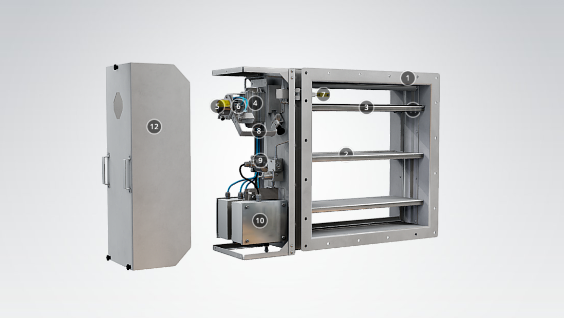
Material
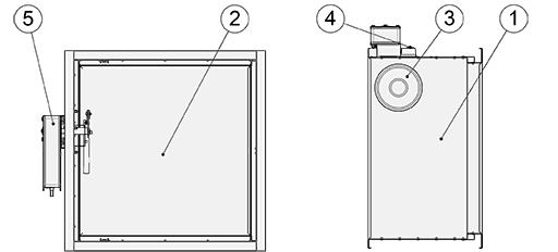
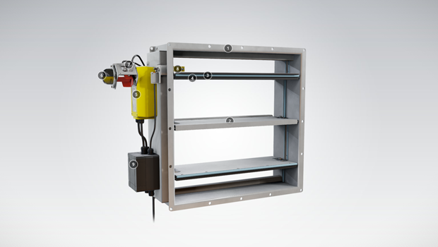
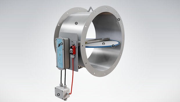
| Nr | Part | Material | Note |
| 1 | Casing | Galvanised steel | Stainless steel options available on request. |
| 2 | Blade | Asbestos free boards made of mineral fibre |
– |
| 3 | Inspection hatch covering | Galvanised steel | – |
| 4 | Fuse | – | Electrical model |
| 5 | Operating model (actuator) | – | Electrical model |
Operating Models
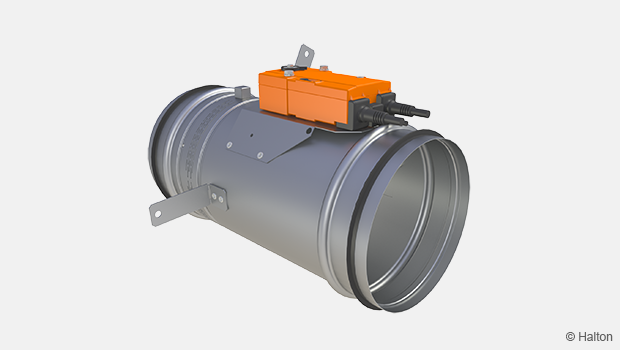
Electric actuator
In the electric actuator (24 V and 230 V) system when a signal from building automation reaches the actuator or the fuse reacts to a rise in temperature (72 °C) the power supply is switched off and the spring closes the damper blade. When the power supply is turned back on (e.g. during routine testing), the actuator opens the damper blade. The actuator is equipped with built-in limit switches for both open and closed position.
These actuators have a visual position indicator and fuses can be replaced from outside the device.
24 V (AC/DC)
The Halton Exe ESR fire damper with the 24 V electric actuator option must be connected to buildings fire damper management control system, e.g. We recommend our fully networked Halton Safe SM2 control and testing system. This system enables the use of smoke detectors in ductwork or room spaces.
Operationally, when the Halton Safe SM2 receives a signal from the fire alarm or smoke detector the power supply is turned off and the spring return actuator drives the damper blade to the closed position. When the power supply is reinstated (e.g. during routine testing) the actuator drives the damper blade to the open position.
The fire damper can also be connected to other commonly used building automation systems.
230 V (AC)
The Halton Exe ESR fire damper with the 230 V electric actuator option must be connected to buildings fire damper management control system.
| Order code | Operating model |
Damper sizes (WxH, mm) |
Operating voltage | Limit switch |
| L1 | BFL 24-T, 4 Nm | 200×200 – 1000×250 |
AC/DC 24 V | ✔ |
| L2 | BFL 230-T, 4 Nm | 200×200 – 1000×250 |
AC 230 V | ✔ |
| F1 | BFN 24-T, 7 Nm | 200×700 – 1000×450 |
AC/DC 24 V | ✔ |
| F2 | BFN 230-T, 7 Nm | 200×700 – 1000×450 |
AC 230 V | ✔ |
| B1 | BF 24-T, 18 Nm | 350×800 – 1000×500 |
AC/DC 24 V | ✔ |
| B2 | BF 230-T, 18 Nm | 350×800 – 1000×500 |
AC 230 V | ✔ |
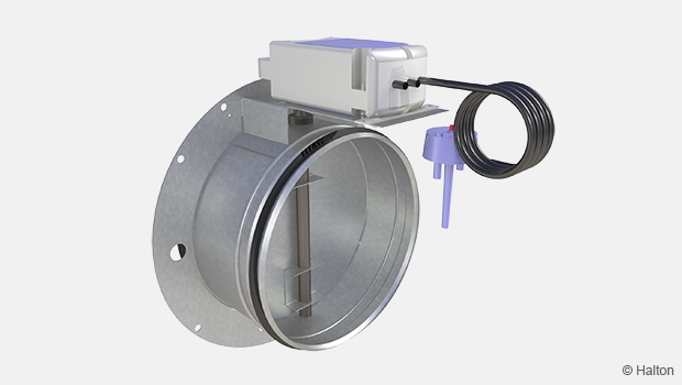
Mechanical spring release (failsafe)
In Halton Exe ESR fire damper with mechanical spring release, the fuse reacts to the rise of temperature (72 ºC) and the mechanical spring closes the damper blade. It needs to be opened manually.
This operating model has a visual position indicator and fuses can be replaced from outside the device.
The fire damper can limit switch (accessory) indicates the damper blade position. When the damper blade is open (safe position), the limit switch indicates this position. If the damper blade is closed (fail safe), the limit switch sends an impulse to the monitoring system. This system triggers an alarm and/or stops/starts fans, depending on the designed system. The limit switch has no influence on the thermal fuse or release mechanism.
The maximum operating voltage and current is 230 V, 5A.
| Limit switch | LS1 | Closed position indication, enclosure class IP 65 |
| Limit switches | LS2 | Open/closed position indication, enclosure class IP 65 |
Function
The Halton Exe ESR fire damper is CE certified for vertical (ve) and horizontal (ho) installation in concrete, masonry or lightweight structures. It fulfils the fire resistance class up EI 120 (ve ho i↔o) S requirements.
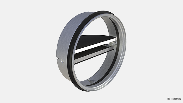
General
Fire dampers are shutters in ventilation duct systems and prevent spreading of the fire and smoke from one fire department to the other. They are equipped with either an electric operating model (actuator) or mechanical spring release (failsafe). Under both options, a fuse reacts to a rise in temperature, causing a spring-return damper blade to close position.
A fire damper with electrical actuator must be connected to a common fire alarm or building automation system.
In the electric actuator (24 V or 230 V) system, when a signal from building automation reaches the actuator or the fuse reacts to a rise in temperature (72 °C), the power supply is switched off, the spring closes the damper blade and seals the duct fire and smoke tightly. When the power supply is turned back on (e.g. during routine testing), the actuator opens the damper blade. The actuator is equipped with built-in limit switches for both open and closed position.
Alternatively, the fire damper can be delivered with a mechanical spring release (fail safe) with a fuse that reacts to the rise of temperature (72 ºC) and the mechanical spring closes the damper. It needs to be opened manually.
Fire damper management system
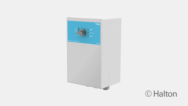
It is recommended that the fire damper with an electrical actuator is connected to an automatic fire damper management system, e.g. Halton Safe Management (HSM) with operating voltage AC 24 V. Testing for fire dampers can be done automatically in Halton Safe SM2.
Only fire damper with 24 V electric actuator can be connected to the Halton Safe SM2 control and testing system. The Halton Safe SM2 enables the use of smoke detectors in ductwork or in the rooms.
Operationally, when the Halton Safe SM2 receives a signal from the fire alarm or smoke detector the power supply is turned off and the spring return actuator drives the damper blade to the closed position. When the power supply is reinstated (e.g. during routine testing) the actuator drives the damper blade to the open position.
The Halton Exe ESR fire damper can also be connected to common building automation systems.
Installation
Please see/download Installation Guide for this fire damper from section Downloads.
Servicing
No regular maintenance is required for the product.
To ensure proper operation of fire dampers, inspection must be carried out regularly according to local building codes. The minimum recommended inspection period is every 6 months. Documentation of testing needs has to be saved for future needs.
A fire damper with electrical actuator must be connected to a common fire alarm or building automation system.
It is recommended that the fire damper with an electrical actuator is connected to an automatic fire damper management system, e.g. Halton Safe SM2 with operating voltage AC 24 V. Testing for fire dampers can be done automatically in Halton Safe SM2.
The fuse of a fire damper equipped with an electric actuator must be replaced if the fuse has been released because of a rise of temperature in the duct. The fuse can be changed from outside the fire damper.
If the fuse of a fire damper with a mechanical spring release (failsafe) is worn out, it must be replaced.
The fire damper is equipped with two inspection hatches, enabling the possibility to check the position of the damper blade. The actuators (electrical and mechanical spring release) include position indicators, open and close
Upon failure during testing of the fire damper, maintenance service shall be ordered from an authorised Halton representative to ensure appropriate operation of the product.
Specification
The fire damper is CE certified and marked according to the standard EN15650 and fire tested according EN 1366-2 standard.
A fire damper of maximum fire resistence class EI 120 (ho ve i↔o) S requirements.
The fire damper casing complies with the tightness requirements for EN 1751 class C. Internal leakage is class 2 according to EN 1751.
The casing of the fire damper is made of galvanised or stainless steel (AISI 316L).
The blade of the fire damper is made of fire resistant asbestos free board (mineral fibre).
The fire damper can be installed both vertical and horizontal position in concrete, masonry or lightweight structures.
The spindle of the blade and the operating models (electric actuator or mechanical spring release) can be installed in vertical or horizontal position in wall installation.
The fire damper can be installed away from the separate element up to 1.0 metre, up to EI 90 (ve ho i↔o) S.
The casing of the fire damper is made of galvanised or stainless steel (AISI 316L).
The blade of the fire damper is made of fire resistant asbestos free boards (mineral fibre).
In all operating models (electric and mechanical spring return), the fuse shall be activated at 72 °C. .
The fire damper with electric operating model includes position indicators, open and close and is equipped with built-in limit switches for both open and closed position.
The fire damper with mechanical spring release includes one position indicator (open) or two position indicators (open and closed). It can be equipped with limit switch(es), open or open and closed.
The smoke control damper is equipped with two inspection hatches, enabling the possibility to check the position of the damper blade.
Order Code
ESR-W-H, RE-FU-ZT
W = Width of duct connection [mm]
200, 250, 300, 350, 400, 450, 500, 550, 600, 700, 800, 900, 1000
H = Height of duct connection [mm]
200, 250, 300, 350, 400, 450, 500, 550, 600, 700, 800
Other options and accessories
MA = Material
GS Galvanised steel
OP = Operating model (actuators)
L1 BFL24-T (72 °C) 24 V, 4 Nm
L2 BFL230-T (72 °C) 230 V, 4 Nm
F1 BFN24-T (72 °C) 24 V, 7 Nm
F2 BFN230-T (72 °C) 230 V, 7 Nm
B1 BF24-T-2 (72 °C), 18 Nm
B2 BF230-T-2 (72 °C), 18 Nm
MA Mechanical spring release
FU = Fuse release temperature
72 72 °C
LS = Limit switch (for mechanical spring release)
NA Not assigned
LS1 Limit switch (closed)
LS2 Limit switches (open/closed)
ZT = Tailored product
N No
Y Yes (ETO)
Order code example
ESR-400-200, MA=GS, OP=L1, FU=72, LS=NA, ZT=N
Downloads
-
Halton Exe ESR – Fire damper (EI 120 S)
Data
en
-
Halton Exe ESR – Palopelti (EI 120 S)
Data
fi
-
Installation Guide – Halton Exe Sturdy Rectangular (ESR)
Data
en_GB -
Asennusohje – Halton Exe Sturdy Rectangular (ESR)
Data
FI -
Palo- ja savunhallintapeltien asennustodistus
Data
Suomi (fi) -
Installation Certificate for Fire Dampers (used in UK)
Data
English (en) -
Declaration of Performance (DoP) – ESR
Data
en_GB -
Construction Product Regulation (CPR) – ESR
Data
en_GB -
Confirmation for installation away from structure
Data
en_GB
"*" indicates required fields
CFD-01 – A0 (A60) E120S Fire damper
product
CFD-01-ICB – EI120S Insulated fire damper
product
CFD-02TM – High temperature tunnel damper
product
FCE – Fire damper (EI 60 S)
product
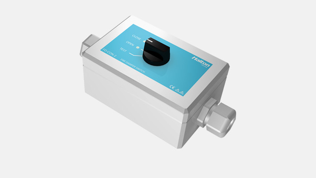
FD-CON-2 – Fire damper control unit
product
FD-CON-A – Fire damper control unit
product
FDA – A0(A60) Fire and gas damper
product
FDB2 – A0(A60) Fire and gas damper
product
FDH – H0(H120) Fire and gas damper
product
FDK – A0(A60) Fire damper
product
FDL – A0(A60) Fire damper
product
FDO – A0(A60) Fire and gas damper
product
Halton Exe EDC – Fire damper (EI 120 S)
product
Halton Exe EFC – Fire damper (EI 120 S)
product
Halton Exe ELC – Fire damper (E 120 S)
product
Halton Exe ELR – Fire damper (E 120 S)
product
Halton Exe ESC – Fire damper (EI 120 S)
product
Halton Exe ESR – Fire damper (EI 120 S)
product
Halton Exe ETC – Fire damper (EI 120 S)
product
Halton Exe ETR – Fire damper (EI 120 S)
product