Product / REP
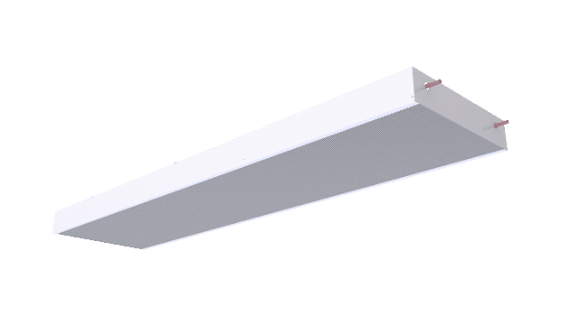
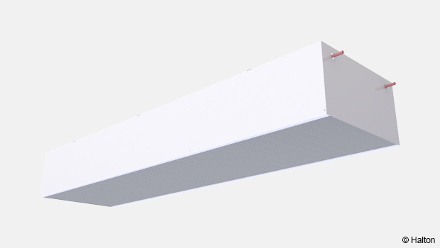
NEW! Halton Rex REP – Passive chilled beam
Halton’s passive chilled beam deliver outstanding energy efficiency and exceptional performance with a remarkably low life-cycle cost.
Operating through natural convection, it provides virtually silent cooling, eliminating the drafts and noise commonly associated with traditional forced-air systems.
Designed for flexibility and seamless integration, this beam feature a modular converter for flush mounting into various ceiling types and are available in two heights to suit diverse architectural requirements.
With no actuators or filters, maintenance intervals are exceptionally long, making passive chilled beam in general ideal for offices, conference rooms, retail spaces, hotels, and healthcare environments. By using water as the primary medium for thermal transport, these systems dramatically reduce energy consumption, supporting building sustainability goals.
- Options for individual or multibeam control
- Available in two heights
- Integrated water valve option for easy installation
Overview
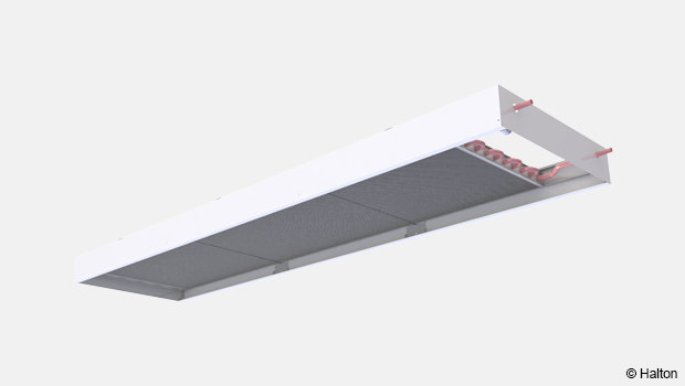
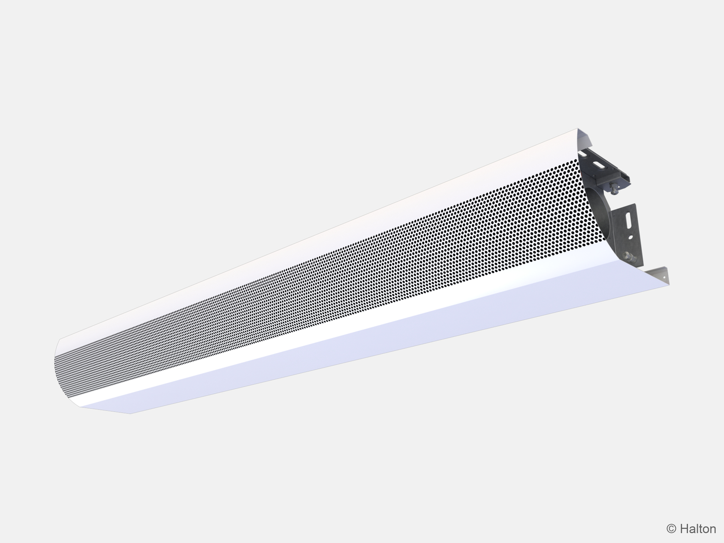
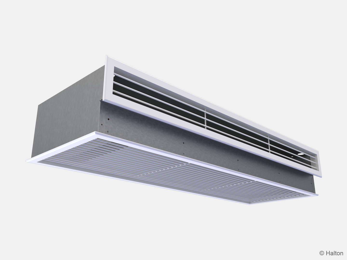
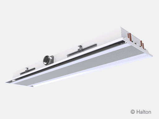
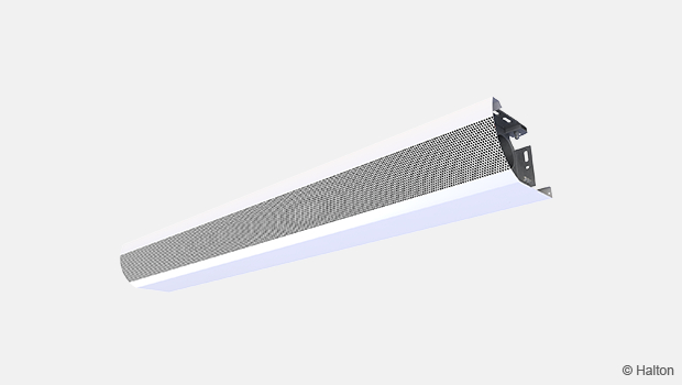
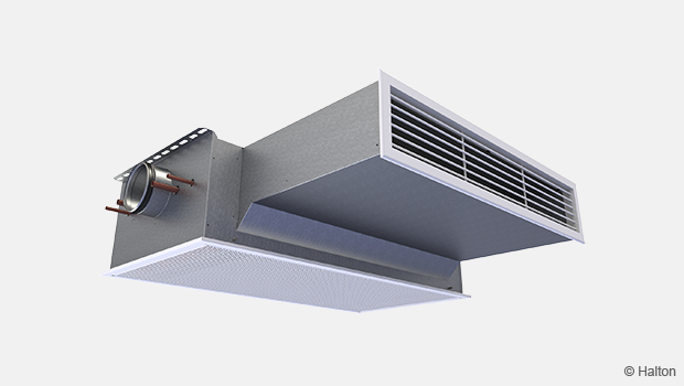
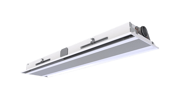
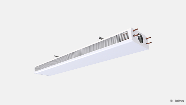
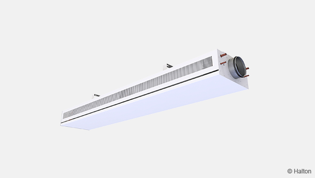
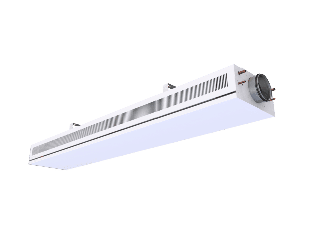
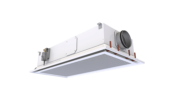
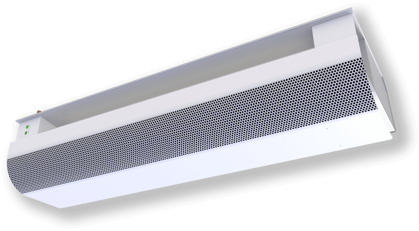
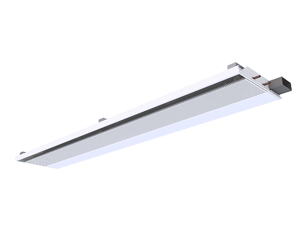
Halton Rex REP passive chilled beam utilise a modular convector design, allowing easy configuration for exposed installation with a suspended ceiling. Because they have no moving parts, it offers long maintenance intervals with low lifecycle costs, making it a cost-effective solution for long-term building operation. The design can accommodate two heights (100 mm and 300 mm) to meet demands, ensuring optimal performance in spaces with different ceiling configurations and load requirements.
This chilled beam can be configured for single- or multiple-beam control, providing flexibility in zoning and energy management. Its quiet operation makes it ideal for noise-sensitive environments. It can be delivered with a water valve and actuator, providing precise temperature regulation that harnesses energy efficiency, lowering the carbon footprint while enhancing indoor air quality and occupant wellbeing.
Application areas
- Office and conference rooms
- Retail
- Hotels
- Healthcare facilities
Key features
- Easy and fast selection with Halton eHIT design tool.
- Well suited for noise-sensitive environments
- Two heights to meet cooling demands 100 mm and 300 mm.
Operating principle
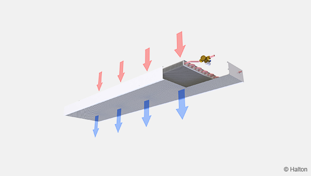
Halton Rex REP passive chilled beam operates through natural convection, drawing warm air from the room toward the beam. As the air passes over the heat exchanger, heat is removed and replaced with cooler air, which gently circulates back into the space. The cooling airflow adjusts automatically in response to the heat load in the occupied zone, maintaining stable and comfortable room conditions.
Cooling output is controlled by regulating the flow of chilled water through the heat exchanger, typically managed by a room thermostat and water valve based on temperature demand. Because passive beams utilise elevated chilled water temperatures, they eliminate the risk of condensation (no latent cooling). Hence, they can capitalise on free-cooling opportunities while reducing energy consumption and enhancing system efficiency.
Features and options
| Category | Option | Description | Note |
|---|---|---|---|
| Coil water pressure drop | CR=N | Normal pressure drop | Low pressure drop option (CR=L) |
| Location of pipe connection | WD = F | Front. For appearence options see Fig. 2 | Options with or without valves |
| WD = T | Top. For appearence options see Fig. 3 | Options with or without valves | |
| Control valves and actuators | CV = NA | Not assigned | – |
| CV = DR1 | RA-C, no actuator | – | |
| CV = DR2 | RA-C, actuator TWA-A 24 V, NC | – | |
| CV = DR3 | RA-C, actuator TWA-A 230 V, NC | – | |
| CV = DA1 | AB-QM, no actuator | – | |
| CV = DA2 | AB-QM, actuator TWA-A 24 V, NC | – | |
| CV = DA3 | AB-QM, actuator TWA-A 230 V, NC | – | |
| Visual appearence | VA = SF | Square edge with front panel. For appearence options see Fig. 4 | Selected options have the same performance data and dimensions. |
| VA = SN | Square edge without front panel. For appearence options see Fig. 5 |
Location of pipe connection

Visual appearence
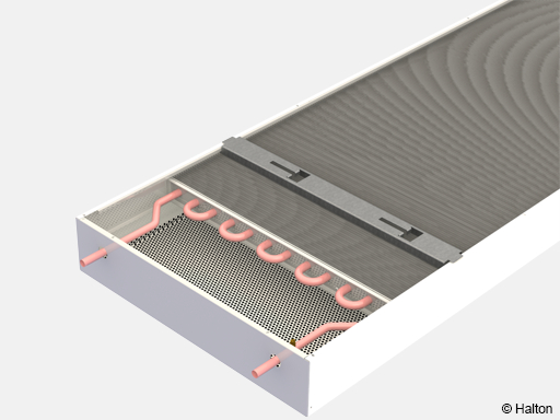
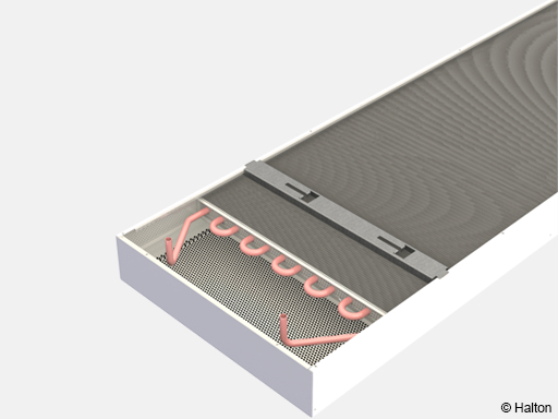
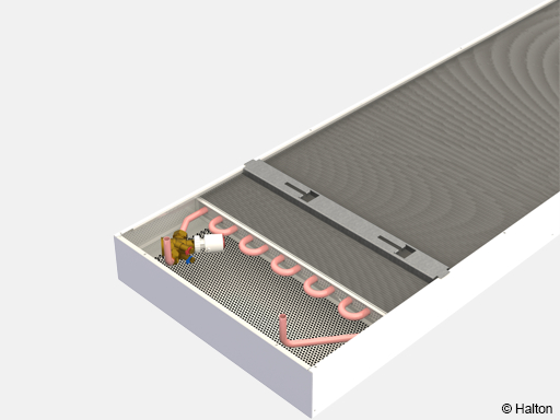
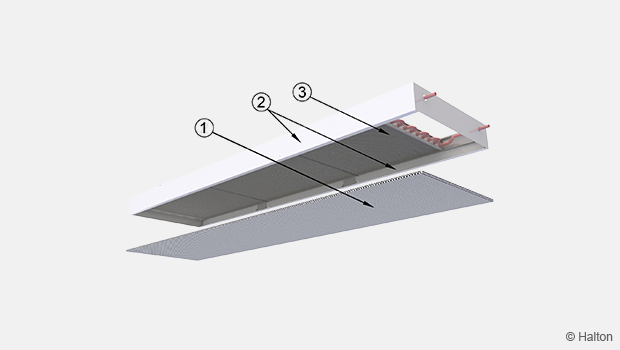
Structure and materials
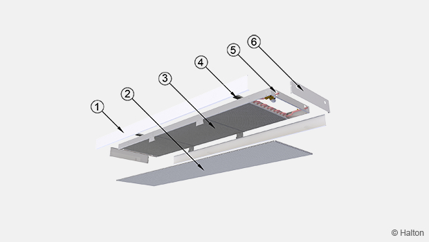
| No. | Part | Material | Description | Note |
|---|---|---|---|---|
| 1 | Side flanges | Sheet metal | Painted | – |
| 2 | Perforated front panel | Sheet metal | Painted | – |
| 3 | Cooling fins | Aluminium | – | – |
| 4 | Movable brackets | Sheet metal | Painted | – |
| 5 | Cooling pipes | Copper | – | Ø 15 mm |
| 6 | End cap | Sheet metal | Painted | – |
Dimensions and weight
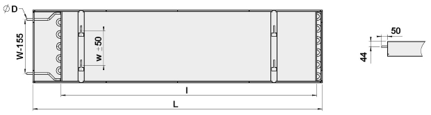
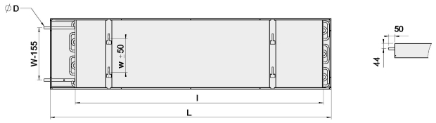
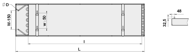
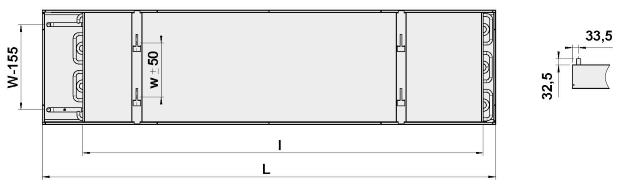
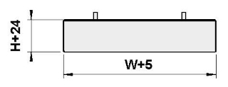
| W | H | w | L | l |
|---|---|---|---|---|
| 300 | 100 | 128 | 1200-4200 | L-300 |
| 400 | 100 | 178 | 1200-4200 | L-300 |
| 600 | 100 | 286 | 1200-4200 | L-300 |
| 300 | 300 | 128 | 1200-4200 | L-300 |
| 400 | 300 | 178 | 1200-4200 | L-300 |
| 600 | 300 | 286 | 1200-4200 | L-300 |
A coil with 1 loop has a connection pipe Ø15 mm and 2 loops has a connection pipe Ø 22 mm.
Weights, [kg/m] (including water)
| Width | Height [100 mm] | Height [300 mm] |
|---|---|---|
| 300 | 9.36 | 12.54 |
| 400 | 11.19 | 14.54 |
| 600 | 13.56 | 17.25 |
Specification
Function
-
The passive chilled beam relies on natural convection, where warm air rised to the beam, which is cooled at the heat exchanger and decends back to the occupied zone.
- Passive chilled beams eliminate the risk of condensation (no latent cooling) because they utilise elevated chilled water temperatures.
Structure
- The unit is an passive chilled beam for exposed installation with suspended ceiling.
- The maximum chilled water pipe work operating pressure is 1.0 MPa.
- The design can accommodate two heights, 100 mm and 300 mm.
- The chilled beam can be equipped with water valves, actuators and cable tray (optional).
- The chilled beam is constructed with metal casing (usually steel and/or aluminium)
- The chilled beam is mounted using threaded drop rods (8 mm) and movable brackets.
Materials
- The front panel and side panels consist of a pre-painted galvanised steel plate (white, RAL 9003 (20% gloss).
- Special colours (RAL xxxx) are available to paint all visible parts.
- The heat exchanger is constructed from aluminium fins and copper connection pipes with Ø15 mm.
- The modular perforated screen (holes 10 mm / 50% free area) is produced in pre-painted sheet metal, RAL 9003 (20% gloss).
- All joints are fully soldered and factory pressure tested.
Packaging and transport
- A removable plastic coating protects each chilled beam.
- The duct connection and pipe ends are sealed for transit.
- Each passive chilled beam is identifiable by a serial number printed on a label attached to the chilled beam.
Installation
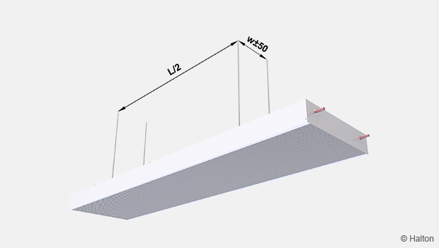
The Halton Rex REP passive chilled beam is modular convector design, allowing easy configuration for exposed installation with a suspended ceiling. The chilled beam position can be easily adjusted both horizontally and vertically.
When selecting of the chilled beam orientation, the location of the water circuit connections are taken into account.
Each beam is equipped with movable brackets fixed on top of the beam and fixed to the ceiling with expansion anchors and threaded drop rods (8 mm, not included in the delivery).
It is recommended that the brackets be positioned one quarter of the unit length (L/4) away from the ends of the beam with 2 brackets option.
With 3 brackets option, it s recommended position two of them one fifth of the unit length (L/5) away from the ends of the beam. The third bracket is recommended to locate in the middle of beam (L/2).
| Beam length [mm] | No. of brackets |
|---|---|
| < 2400 | 2 |
| ≥ 2400 | 3 |
The exact positions of the brackets are adjusted according to the rod position.
| W [mm] | w [mm] |
|---|---|
| 300 | 128 |
| 400 | 178 |
| 600 | 286 |
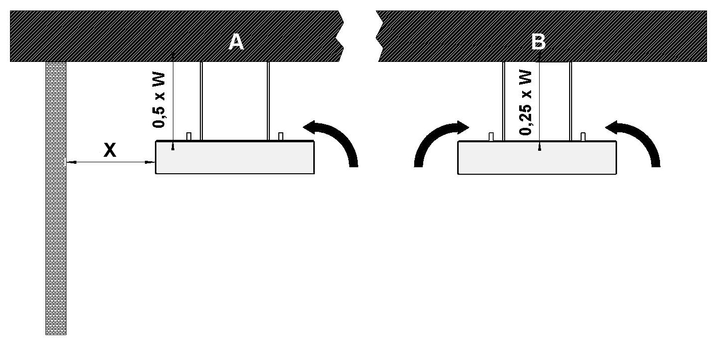
| A | Chilled beam installed close wall: Distance (X) same as the width of beam or less, airflow mainly in one direction. |
| B | Chilled beam installed further from walls: Airflow from both directions. |
A = Chilled beam installed close wall: Distance (X) same as the width of beam or less, airflow mainly in one direction.
B = Chilled beam installed further from walls: Airflow from both directions.
To ensure effective convection, the beam should be installed:
-
Close to the wall (see Fig. 13-A)
- Distance from the ceiling: Minimum = width of chilled beam x 0.50
- Distance from the wall: Same as the width of beam or less
-
Further from walls (see Fig.13-B)
- Distance from the ceiling: Minimum = width of chilled beam x 0.25
- Distance from the wall: Width of beam or more
- Airflow from both directions
Commissioning
The following are the standard practices for commissioning the chilled beam:
-
Fill up and flush the main pipelines
- This involves filling the system’s main water pipelines with clean water and flushing out any debris, air, or contaminants that may be present. It ensures the system starts with clean water and prevents blockages or damage to components.
-
Fill up and vent the beam circuits
- Fill each chilled beam circuit with water and vent it to remove trapped air. Air pockets can hinder water flow and reduce cooling efficiency, so venting ensures proper circulation.
-
Adjust the flow water temperature set point
- Set the desired temperature for the water circulating through the system. The temperature set point affects the cooling performance and energy efficiency of the chilled beams.
-
Adjust water flow rates with the balancing valves in all main pipelines to the correct value
- Balancing valves are used to regulate and equalise water flow across the system. Adjusting them ensures that each part of the system receives the correct flow rate, which is crucial for consistent performance.
-
Adjust water flows in all chilled beams to the correct value
- Each chilled beam must receive the appropriate water flow to function optimally. This step involves fine-tuning individual beam valves to match design specifications, ensuring uniform cooling across the space.
Maintenance
| No. | Parts |
|---|---|
| 1 | Front panel |
| 2 | Casing |
| 3 | Cooling coil |
- Minimal maintenance required: The unit is designed for low maintenance and long-term reliability.
- Cooling coil cleaning: Depending on room conditions and air quality, clean the cooling coils every 3 to 5 years.
- Cleaning the casing: Wipe the outer casing with a damp cloth to remove dust and surface dirt.
- Cleaning the cooling coil: Use a vacuum cleaner to gently remove dust and debris from the coil, avoiding damage to the fins.
Order code
REP-H-L-W; WD-CR-VA-CV-CO-ZT
| Main options | |
|---|---|
| H = Height [mm] | 100, 300 |
| L = Length [mm] | 1200, +600, …, 4200 |
| W = Width [mm] | 300, 400, 600 |
| Other options and accessories | |
|---|---|
| WD = Location of pipe connection | |
| F | Front |
| T | Top |
| CR = Coil water pressure drop | |
| N | Normal |
| L | Low |
| VA = Visual apprearence | |
| SF | Square edge with front panel |
| SN | Square edge without front panel |
| CV = Control valves and actuators | |
| NA | Not assigned |
| DR1 | RA-C, no actuator |
| DR2 | RA-C, actuator TWA-A 24 V, NC |
| DR3 | RA-C, actuator TWA-A 230 V, NC |
| DA1 | AB-QM, no actuator |
| DA2 | AB-QM, actuator TWA-Q 24 V, NC |
| DA3 | AB-QM, actuator TWA-Q 230 V, NC |
| CO = Colour | |
| SW | Signal white (RAL 9003) |
| X | Special colour (RAL xxxx) |
| ZT = Tailored product | |
| N | No |
| Y | Yes (ETO) |
| Order code example | |
|---|---|
| REP-100-2400-400; WD=F, CR=N, VA=SF, CV=NA, CO=SW, ZT=N |
Downloads
"*" indicates required fields
Halton CaBeam – Chilled beam for exposed wall installation
product
Halton CaBeam – Chilled beam for integrated installation
product
Halton CaBeam – Chilled beam for recessed installation
product
Halton CBH – Chilled beam
product
Halton CHB – Chilled beam
product
Halton CPA – Passive chilled beam
product
Halton CSW – Swirl comfort unit
product
Halton Rex R6W – Variable air volume chilled beam (VAV)
product
Halton Rex RE6 – Chilled beam
product
Halton Rex REE – Chilled beam
product
Halton Rex REO – Chilled beam (VAV)
product
Halton Rex REW – VAV chilled beam
product
Halton Rex RXP – Chilled beam (CAV/VAV)
product

Halton Vita VPR – Hygienic chilled beam
product
NEW! Halton CaBeam REC – For Passenger and Crew Cabins
product
NEW! Halton Rex REP – Passive chilled beam
product
NEW! Halton Rex RSI – Slim induction unit
product