Product / REW
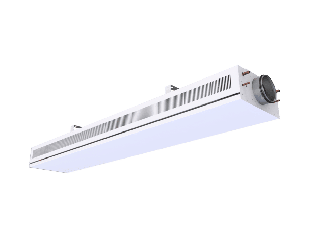
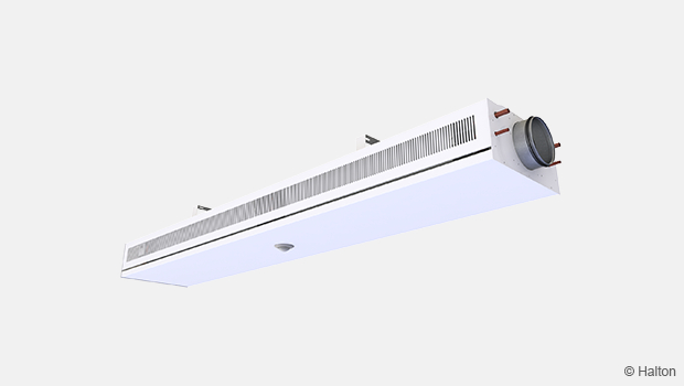
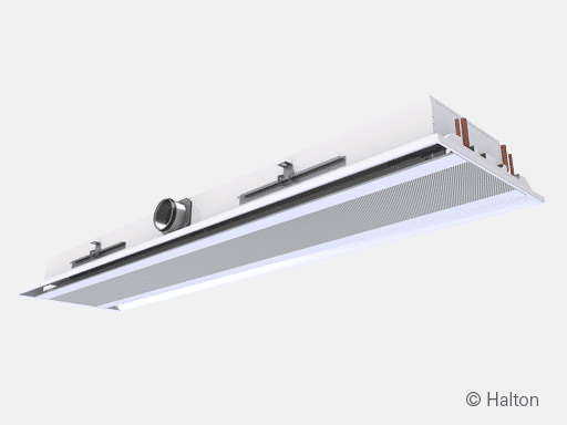
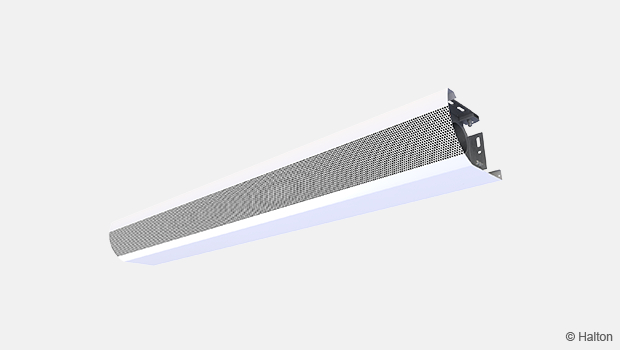
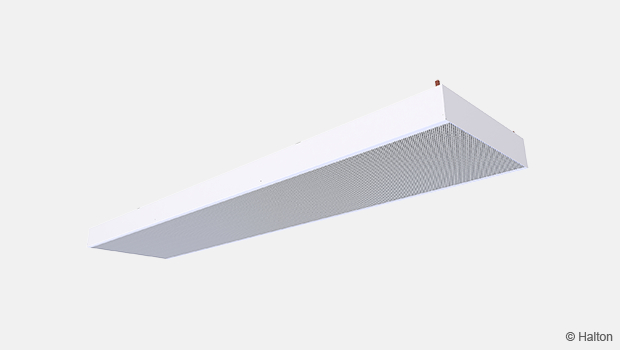
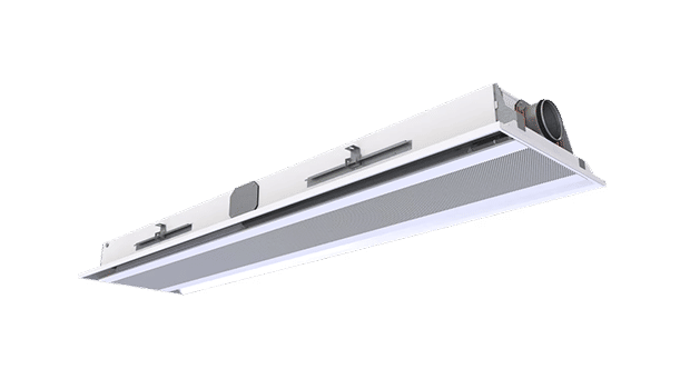
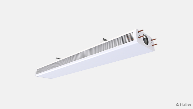
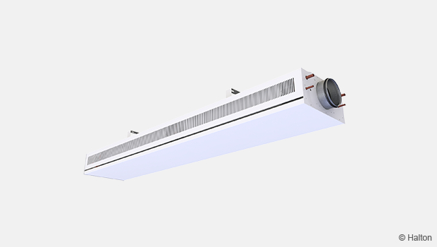
Halton Rex REW – VAV chilled beam
Halton Rex REW is an exposed, variable air volume chilled beam that combines the efficiency of chilled beams with variable airflow control to optimise thermal comfort and energy efficiency. It is suitable for advanced Halton Workplace control systems, designed for energy efficiency and demand-controlled ventilation in buildings. This chilled beam is particularly well-suited for office applications, including enclosed offices, open-plan spaces, and public areas.
Halton Rex REW also contributes to sustainable performance by helping reduce its carbon footprint, which impacts the environment throughout its lifecycle.
- Combines cooling, heating, and ventilation in a single quiet, efficient system
- The Operation Mode Damper (OMD) provides an adjustable supply airflow rate.
- In-built flexibility for partition wall relocations with Halton Velocity Control (HVC).
- Two product models (Flexible and Autonomic) with adjustable airflow using manual CAV or motorised VAV.
- This active chilled beam is fully adaptable for customised design solutions.
-
E.g. Sensors and lights are easy to integrate into the unit.
-
Overview
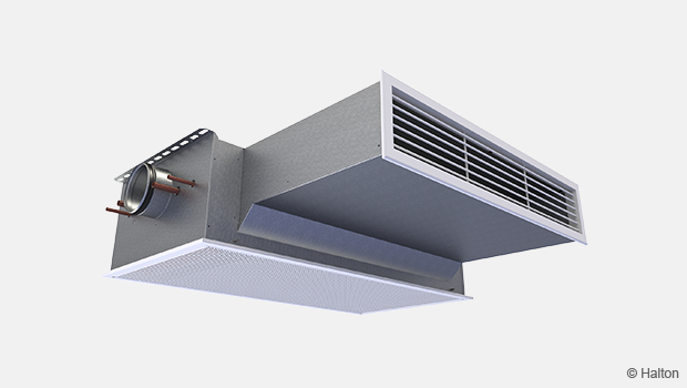
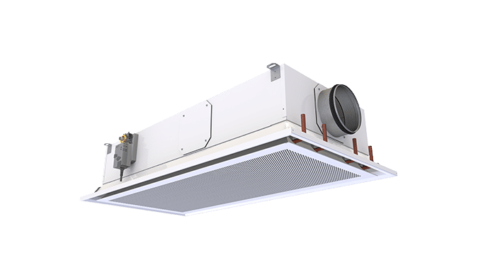
Halton Rex REW chilled beam is a versatile solution designed for demand-based ventilation systems. It serves as a combined cooling, heating, and supply air unit for exposed installation with suspended ceiling. Its compatibility with both pressure-dependent constant static pressure ductwork and pressure-independent ductwork makes it well-suited for demand-based ventilation. It is particularly effective in applications that prioritize high-quality indoor conditions, energy-efficient operation, and individual room control.
Halton Rex REW chilled beam is designed for high-quality office requirements with high flexibility of airflow adjustability. The operation of this chilled beam will adapt to changes in the use of the space and office layout changes.
Application areas
- Office rooms
- Public spaces
- Landscape offices and meeting rooms
Key features
- Easy and fast selection with Halton eHIT design tool.
-
Suitable for demand based Halton Workplace control systems.
- Adjustable supply airflow rate changes with Operation Mode Damper (OMD).
- Individually adjustable velocity conditions and an in-built flexibility of operation for partition wall relocations with Halton Velocity Control (HVC).
- Well suited for spaces with high cooling loads, low humidity loads, and demand-based ventilation requirements.
- Two product models with adjustable airflow using manual CAV or motorised VAV.
- Flexible model with 0-100% airflow control and pressure-dependent operation.
- Autonomic model with 0-100% airflow control and pressure-independent operation.
- Ideal solution for applications where high-quality indoor conditions, energy-efficient operation and individual room control are appreciated.
- Demand based ventilation for efficient use of energy in constant-pressure ductwork zone applications.
- Enhanced life cycle performance with optimised air and water flow rates.
- Model with combined cooling and heating coil.
- A model with Halton Workplace WRA room automation system package available.
Operating principle
The Halton Rex REW is an active variable air volume chilled beam for exposed installation.
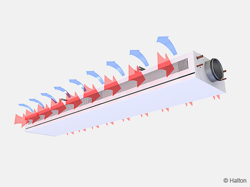
The primary supply air enters the plenum of the active chilled beam, from which the air diffuses into the room through precision engineered nozzles controlled by the Operation Mode Damper (OMD). The supply slots, positioned on the top of the beam, ensure optimal air distribution.
As the high-velocity supply air exits the nozzles, it generates jets that effectively induce ambient room air into the unit. The built-in heat exchanger then conditions this induced air, either cooling it or heating it as required. The resulting mixed airflow is discharged horizontally along the ceiling surface, which enhances air circulation and ensures uniform thermal comfort throughout the space.
The recommended minimum distance is 600 mm from the wall and 100 mm from the ceiling.
Velocity control in the occupied zone
The Halton Velocity Control (HVC) is used to adjust room air velocity conditions either when the room layout is changed, (e.g., in cases where the chilled beam is located near the partition wall) or when local, alter the individual velocity conditions. The HVC adjustment impacts the induced room airflow through the heat exchanger. Therefore, it either increases or decreases both the velocities in the occupied zone and the cooling/heating capacity of the chilled beam.
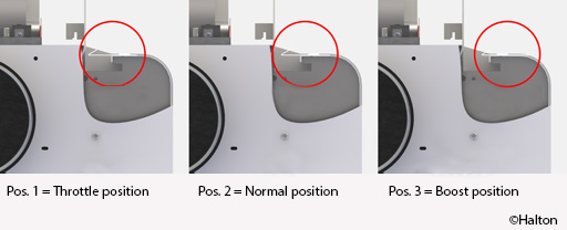
The HVC involves manual velocity adjustment in three different positions 1 = Throttle, 2 = Normal, and 3 = Boost, as shown in Fig. 3. The HVC system is divided into sections to enable the adjustment of conditions in different parts of the occupied zone. Depending on the length of the beam, the optimal HVC damper module lengths are between 500 and 1400 mm. It enables the adjustment of conditions in different parts of the occupied zone.
The HVC damper is divided into sections (Pos. 1-3) to enable the adjustment of conditions in different parts of the occupied zone.
It is recommended to design the chilled beam in the normal position, to allow both throttle and boost functions during the building’s life cycle.
System airflow control
The supply airflow of the chilled beam nozzle jets depends on the nozzle type, nozzle row length, and static chamber pressure. The Operation Mode Damper (OMD, shown in green in Fig. 4) is used to adjust and control the fresh air flow rate in a room. The airflow rate is dependent on the opening position of the control damper. The room’s operation mode is monitored with an occupancy sensor.
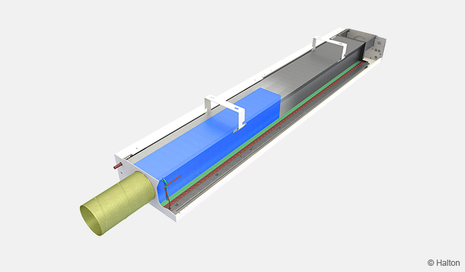
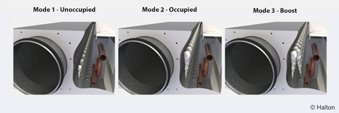
The figure below (Fig. 5.) presents the function in different modes controlled by the OMD.
-
Unoccupied mode: In this mode, supply air rate is set to a minimum value that can remove material emission.
- Occupied mode: In this mode, set the supply air rate to normal office mode.
- Boost mode: When more persons are in the space, based on the CO2 sensor, airflow is increased to boost mode to maintain the set target value of indoor air quality.
Chilled beams for demand-based airflows can be connected to any kind of duct work zones. Constant pressure ductwork zone gives advantages for easier design and operation.
Flexible model
The Halton Operation Mode Damper (OMD) in the Halton Rex REW Flexible model is used for manual supply airflow adjustment or motorised Variable Air Volume (VAV) control of the supply airflow rate.
The OMD control can be used as a Constant Air Volume (CAV) damper. That is, it can adjust the k-factor to achieve the correct airflow with a certain pressure level. It removes the need for changing or plugging the nozzles of the Halton Rex REW chilled beam supply air control.
It is recommended that Halton Rex REW Flexible model chilled beams for demand-based airflows be connected to a constant-pressure ductwork zone.
Autonomic model
The Halton Operation Mode Damper (OMD) in the Halton Rex REW Autonomic model is used for manual supply airflow adjustment or motorised Variable Air Volume (VAV) control of the supply airflow rate. In this Halton Rex REW Autonomic model, when the OMD control is equipped with a motorised actuator integrated with pressure measurement, fully flexible VAV control with pressure-independent operation is achieved. It allows different pressure-independent VAV modes with, for instance, minimum, normal, and boost airflow settings.
Halton Rex REW Autonomic model chilled beams can be used in any type of ductwork zone. The design of a chilled beam should ensure both minimum and maximum ductwork pressure levels with variable pressure levels in the ductwork.
Temperature control
It regulates the water flow rate, controlling the cooling and heating capacities of the chilled beam in response to the control signal from the room temperature controller.
In heating mode, it is recommended that the temperature difference between the jet outlet and room air be no greater than 3 °C. The inlet water temperature of the heat exchanger should also be no higher than 35 °C. Optimal heating performance requires an appropriate primary airflow rate. Thus, the air handling unit shall operate during heating periods to ensure proper heating performance.
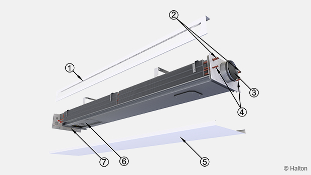
Structure and materials
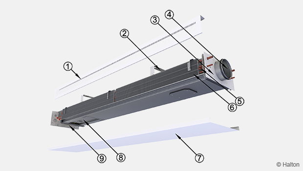
| No. | Part | Material | Description | Note |
|---|---|---|---|---|
| 1 | Coil covers | Pre-painted galvanised steel | Polyester-painted, white (RAL 9003, 20% gloss) | Special colours available. Polyester-epoxy-painted |
| 2 | Brackets | Galvanised steel | Polyester-epoxy-painted, white (RAL 9003, 20% gloss) | Special colours available |
| 3 | End plates | Galvanised steel | Polyester-painted, white (RAL 9003, 20% gloss) | Special colours available. Polyester-epoxy-painted |
| 4 | Supply air plenum | Galvanised steel | – | – |
| 5 | Coil pipes | Copper | – | – |
| 6 | Coil fins | Aluminium | – | – |
| 7 | Front panel | Pre-painted galvanised steel | Polyester-painted, white (RAL 9003, 20% gloss) | Special colours available Polyester-epoxy-painted |
| 8 | Controller | – | – | – |
| 9 | Control valves and actuators | – | – | – |
Cooling/heating water pipe connections are Cu12/Cu15 with wall thickness of 0.9-1.0 mm fulfilling European Standard EN 1057:1996.
The maximum chilled/hot water circuit operating pressure is 1.0 MPa @ 70 ºC.
Features and options
| Accessory | Code | Description | Note |
|---|---|---|---|
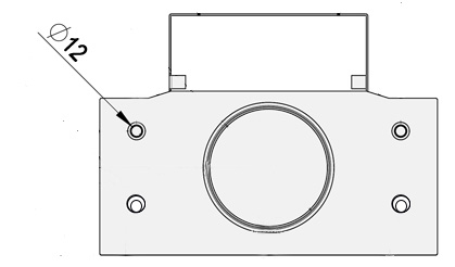
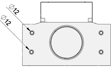
| Cooling coil | TC = C | Coil with chilled water circulation | Cooling copper water pipe connections are Ø 12 mm with normal pressure drop and Ø 15 mm with low pressure drop. (see “Dimensions” section) |
| Combined cooling and heating coil | TC = H | Coil with hot water circulation | Cooling and heating copper water pipe connections are Ø 12 mm. (see “Dimensions” section) |
| Coil pressure drop | CR=N | Normal pressure drop | Low pressure drop option (CR=L) |
| Venting valves | VV = Y | Equipped with venting valves | – |
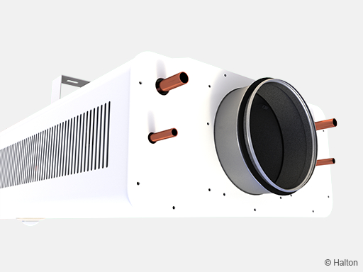
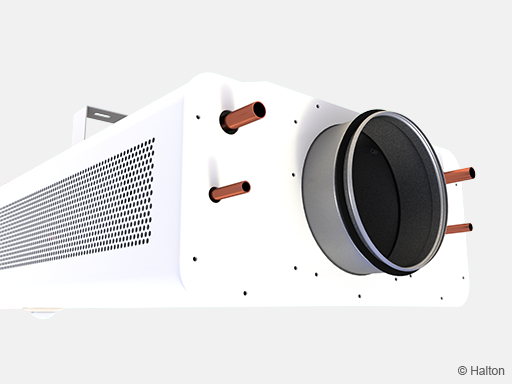
| Visual appearance | VA=See section Order code | For appearance options see | Selected options have the same performance data and dimensions. |
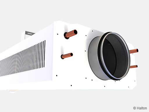
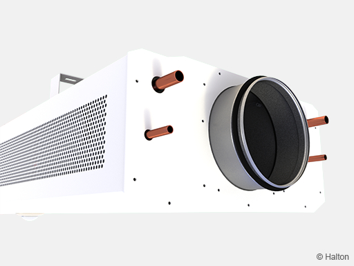
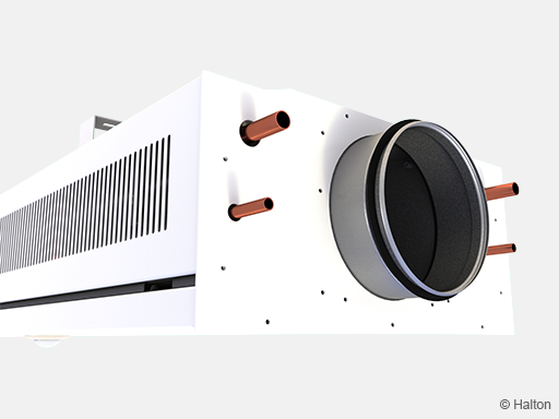
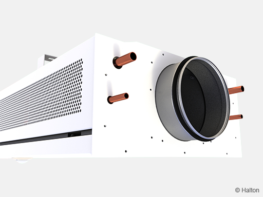
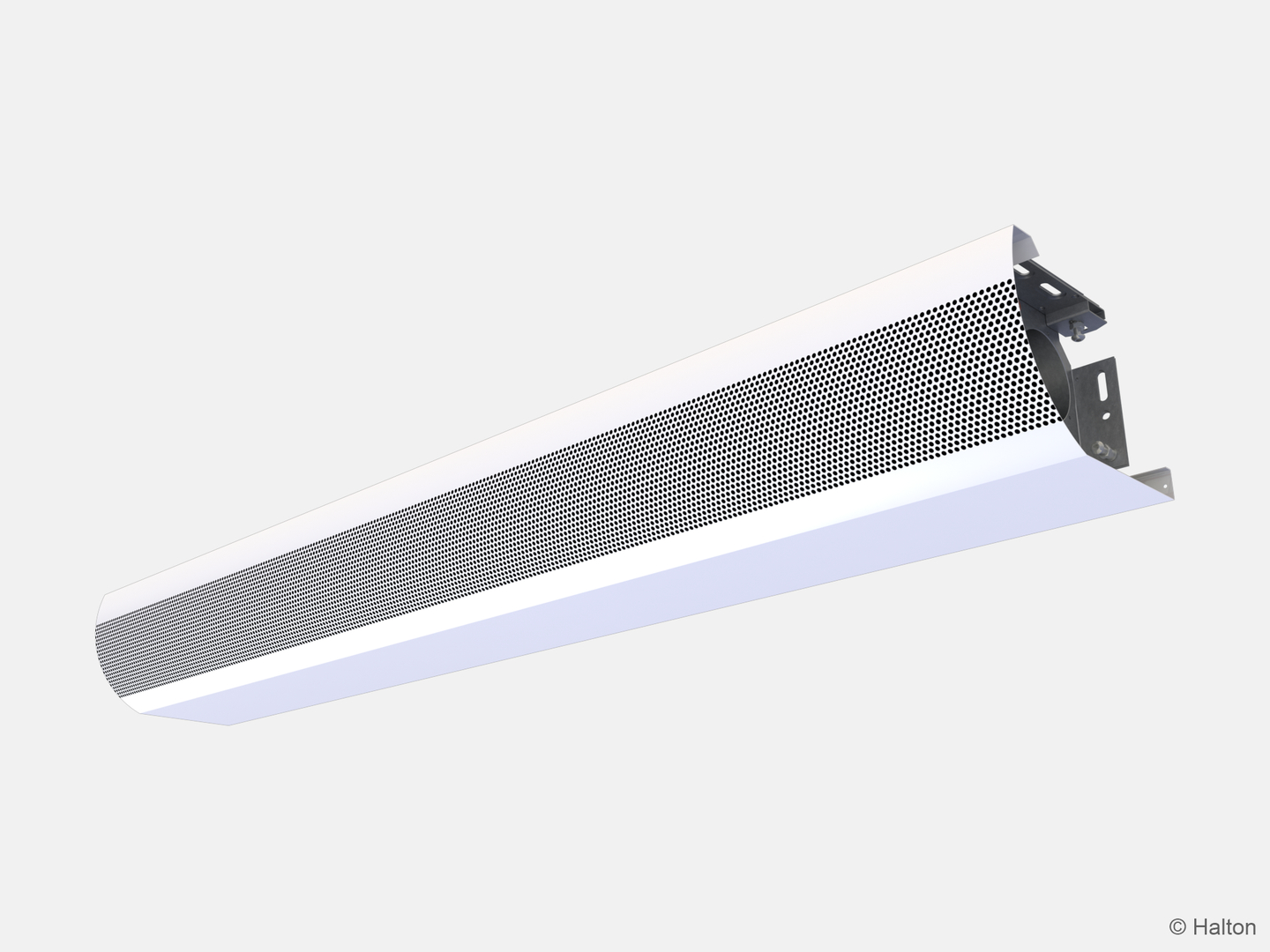
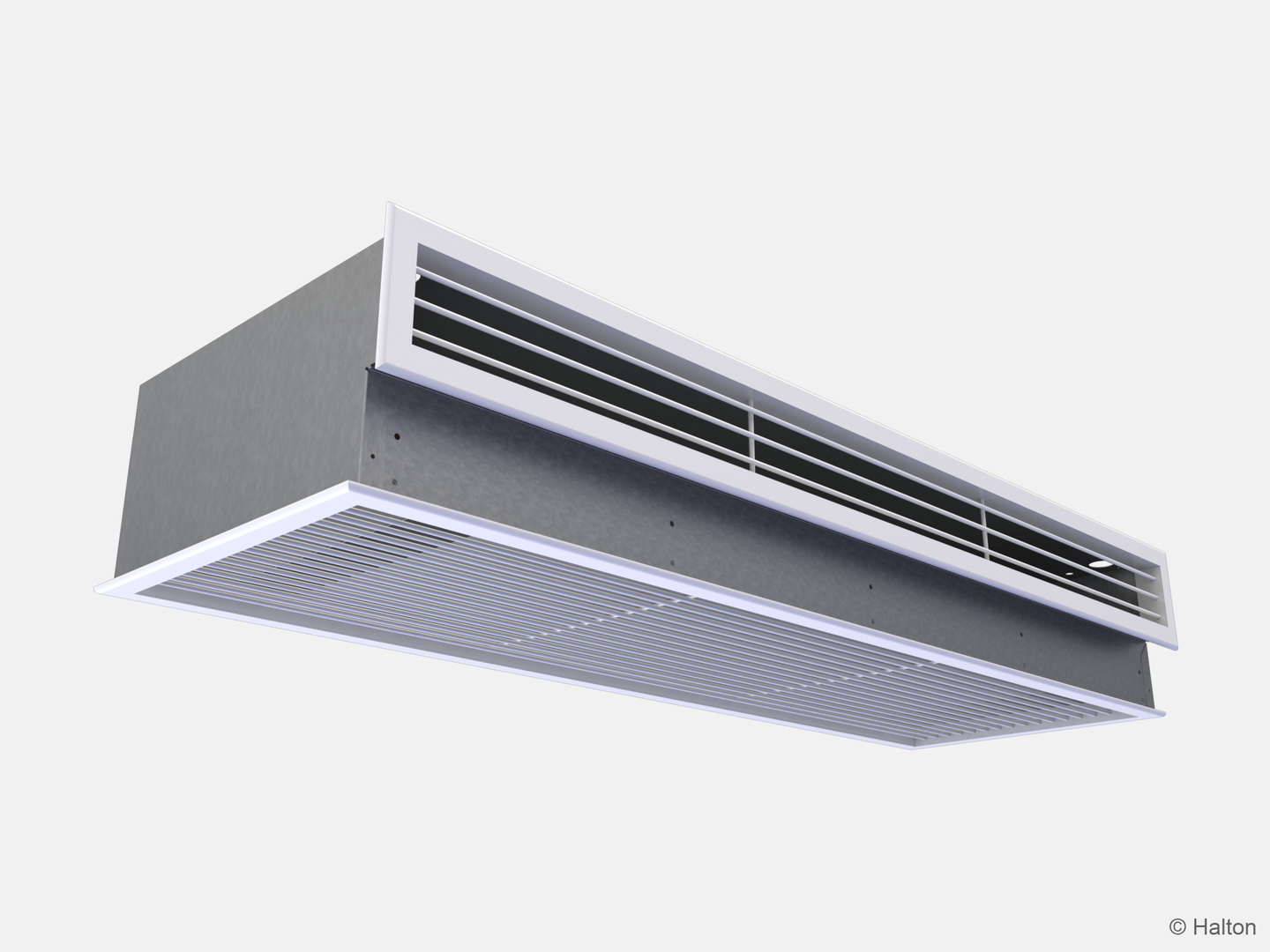
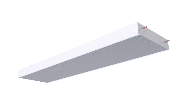
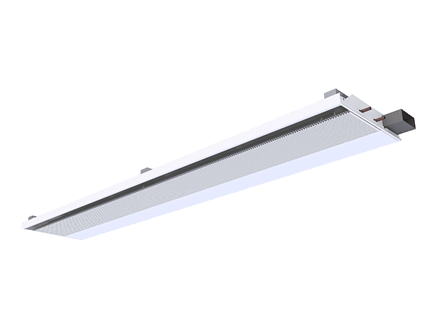
Visual apprearance options (VA)
Dimensions and weight

| ØD | Coil length [mm] | Lengh L-5 [mm] | Weight [kg/m, water excluded] |
|---|---|---|---|
| 160 | 1500, +100, …, 3300 | 1800, +100, …, 3600 | 17 |
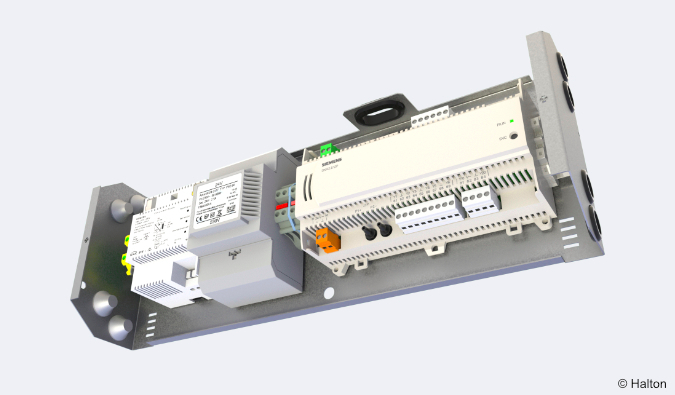
System package
If required, the system package includes a valve with actuator, controller, humidity sensor, CO2 sensor, and temperature sensor.
Halton Workplace WRA room automation system package for Halton Rex REW.
Halton Workplace WRA is part of the Halton Workplace solution offering.
Halton Workplace WRA is a controller specially designed to control the automation system of office spaces and meeting rooms. It controls ventilation airflow, room temperature, and indoor air quality.
Halton Workplace WRA room automation package consists of a controller unit and optional components depending on customer needs: a wall panel and sensors for temperature, CO2, occupancy, pressure, and condensation.
Depending on the number of controls and sensors required, the controller unit and wall panel are available in options. The Halton Workplace WRA room automation controller is always combined with other Halton products for an adaptable and high-level indoor climate.
Application area
- Controlling the ventilation airflow, room temperature, and indoor air quality in office spaces and meeting rooms
- The Halton Workplace WRA room automation controller is an essential part of the Halton Workplace system, controlling room units and airflow control dampers.
- Overall Halton Workplace system includes the following:
- Room air conditioning applications with Halton Workplace WRA room automation controller:
- Active chilled beams
- Exhaust units
- VAV dampers
- Active VAV diffusers
- Room air conditioning applications with Halton Workplace WRA room automation controller:
- Halton Max MDC zone control dampers
- Halton Workplace WSO system optimiser
Key features
- Factory-tested controller and wiring, easy to install
- Pre-installed project-specific parameters, quick to commission
- Several operating modes based on occupancy, thermal comfort, and indoor air quality
- Enables fully flexible layout solutions for changing needs in office environments
- Highly energy-efficient and reliable system operation
Operating principle
The Halton Workplace WRA room automation controller operates with the Halton Workplace system’s Variable Air Volume (VAV) dampers and active chilled beams. These dampers adjust ventilation airflow, room temperature, and indoor air quality in office spaces.
Each room unit in an office space can have its own dedicated Halton Workplace WRA room automation controller, or a single controller can control multiple room units. The Halton Workplace WRA room automation controller can automatically adjust the system according to users’ preferred indoor environment level, bringing maximum flexibility.
Room automation: Halton Rex REW active chilled beams controlled with Halton Workplace WRA room automation controllers
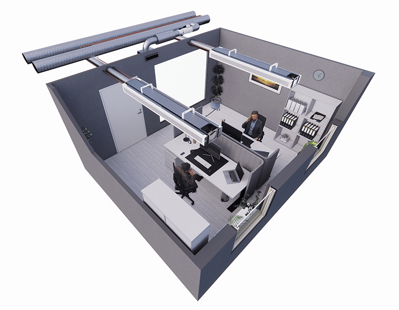
Room automation
In this configuration, two Halton Workplace WRA room automation controllers (DXR2.E12P-102A) control two Halton Rex REW active chilled beams. Each chilled beam has heating and cooling valves, a motorised control, and integrated CO2 and condensation sensors. Halton Workplace WRA room automation controller has an integrated pressure sensor. The system also includes an exhaust VAV damper and a wall panel (QMX3.P37) with a temperature sensor and display. One Halton Workplace WRA room automation controller can individually control up to four terminal units, and there can be several Halton Workplace WRA room automation controllers in the room.
Design criteria for room automation
- Chilled beam has heating and cooling valves
- Halton Rex REW chilled beam has motorised OMD control
- Condensation and CO2 sensor integrated into Halton Rex REW chilled beam
- Exhaust airflow control
- Wall panel with temperature sensor and display
- Window switch control
- Pressure sensor integrated into Halton Workplace WRA room automation controller
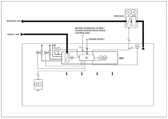
Equipment list
| Code | Equipment |
|---|---|
| RC | Controller unit |
| FG | Airflow damper actuator |
| FC | Airflow measurement |
| H | Water valve actuator |
| CS | Condensation sensor |
| OS | Occupancy sensor |
| PE | Pressure sensor |
| CO2 | CO2 sensor |
| WP | Wall panel |
| TE | Temperature sensor |
| TI | Temperature display |
Wiring diagram
For the wiring diagram of this configuration, see the Halton Workplace WRA room automation controller’s product page or the section Product selection examples.
Components and order code examples for the system
- 2 x Active chilled beam: Halton Rex REW
- REW-F-B-1800-B; SP=N, TC=C, CR=N, VV=N, CN=M1, VA=RO, CO=SW, ZT=N
- 1 x Exhaust unit: Halton AGC Exhaust grille + Halton PRL Plenum for grilles
- AGC-N-400-100 FS=CL, ME=A, FI=PN, CO=W, ZT=N + PRL-F-400-100-160
- 1 x VAV damper: Halton Max MUC or Halton Max MOC
- MUC-G-160, MA=CS
- 2 x standby, shut-off damper: Halton PTS
Specification
Function
- The unit is an active chilled beam for exposed installation with a bi-directional air supply.
- When static chamber pressure is kept constant, the primary airflow rate is adjustable from minimum to maximum (0-100%).
- The induced room airflow rate is manually adjustable to three positions without influencing the primary air supply flow rate.
- The chilled beam unit contains a motorised Operation Mode Damper (OMD).
- The maximum operating pressure of the pipework is 1.0 MPa @ 70 °C.
Structure
- The front panel is openable and detachable from either side to allow maintenance and cleaning.
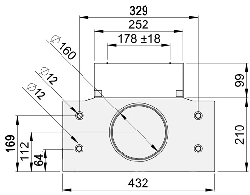
- The chilled beam is 432 mm wide and 210 mm high, and the inlet duct diameter is 160 mm.
- The chilled beam can have a duct cover to cover the connection duct and pipe installations (optional).
Materials
- The front panel and side panels consist of a pre-painted galvanised steel plate (white, RAL 9003).
- Special colours (RAL xxxx) are available to paint all visible parts.
- All pipes are made of copper, and the connection pipe’s wall thickness is 0.9-1.0 mm.
- The fins of the heat exchanger are made of aluminium.
- Heat exchanger incorporates heating via two 12 mm pipes connected in series.
- All joints are factory pressure-tested.
Packaging and transport
- A removable plastic coating protects each chilled beam.
- The duct connection and pipe ends are sealed for transit.
- Each chilled beam is identifiable by a serial number printed on a label attached to the chilled beam.
Installation
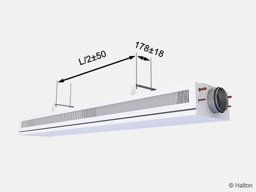
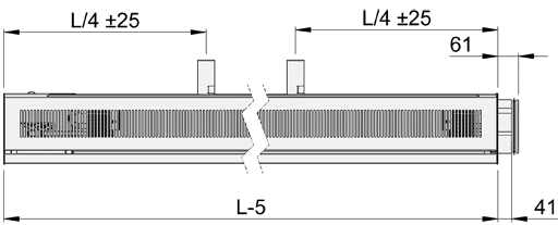
The Halton Rex REW active chilled beam is suitable for exposed installation in the ceiling, typically lengthwise in the room. The beam should be positioned no closer than 600 mm from the wall and 100 mm from the ceiling. The chilled beam ceiling brackets can be fixed directly to the ceiling surface or suspended using threaded drop rods (8 mm). Position the brackets one-quarter of a unit length (L/4) away from the end of the beam.
Install the main pipelines of the cooling and heating water loops above the level of the chilled beams to enable venting of the pipework.
Installation with brackets
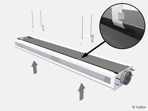
Fixing of the beams done by pushing the beam to the ceiling brackets. Secure all fixing points so that they are properly locked to the fixing slots.
Commissioning
Cooling
The recommended cooling water mass flow rate is 0.02-0.10 kg/s, resulting in a temperature rise of 1-4 °C in the heat exchanger. To avoid condensation, the recommended inlet water temperature of the heat exchanger is 14-16 °C.
Heating
The recommended heating water mass flow rate is 0.01-0.04 kg/s, resulting in a temperature drop of 5-15 °C in the heat exchanger. The maximum temperature of the inlet water for the heat exchanger is 35 °C.
Balancing and control of water flow rates
Adjustment valves installed on the back end of the Halton Rex REW chilled beam balance the water flow rates.
The water mass flow rate, which can be controlled using an ON/OFF valve or a two—or three-way proportional valve, controls the chilled beam’s cooling and heating capacities.
Adjustment of supply airflow rate
Connect a manometer to the measurement tap and measure the static pressure in the Halton Rex REW chilled beam. Fig. 20 presents the measurement tab locations for OMD (Operation Mode Damper) and chambers 1 and 2.
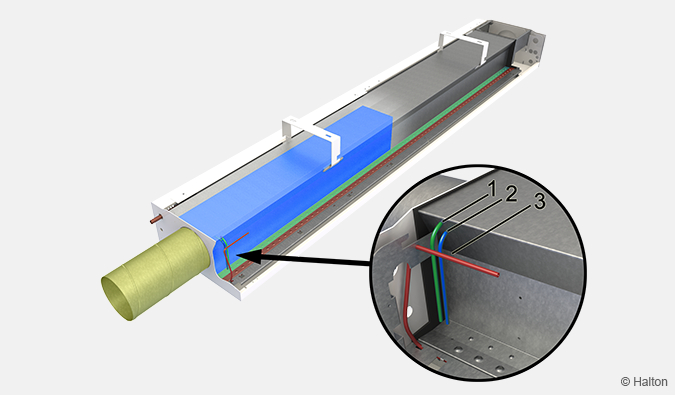
Key:
| No. | Location | Colour |
|---|---|---|
| 1 | Chamber 1 | Green |
| 2 | OMD | Blue |
| 3 | Chamber 2 | Red |
Total airflow rate (q v )
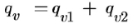
| qv | Total airflow rate, l/s or m3/h |
| qv1 | Chamber 1 nozzle jet airflow rate, l/s or m3/h |
| qv2 | Chamber 2 nozzle jet airflow rate, l/s or m3/h |
| leff | Length of the coil (beam length – 200 mm) |
| Δ pm | Chamber 1 measured pressure for qv1 or Chamber 2 measured pressure for qv2 |
| k [l/s] | k [m3/h] | |
|---|---|---|
| A | 0,71 | 2,56 |
| B | 1,01 | 3,64 |
| C | 1,41 | 5,08 |
| D | 2,08 | 7,49 |
The same k-factors will be used for all the operation modes.
Please note the leff may differ between the normal and boost modes.
Maintenance
Key:
| No. | Parts |
|---|---|
| 1 | Coil cover |
| 2 | Chilled water pipe connection |
| 3 | Supply air connection |
| 4 | Heating water pipe connection |
| 5 | Front panel |
| 6 | Controller |
| 7 | Control valves and actuators |
Open the front panel of Halton Rex REW. Clean the supply air plenum, duct, and finned coils of the heat exchanger using a vacuum cleaner, taking care not to damage the finned coils. Clean the front panel and, if necessary, the side plates with a damp cloth.
Order code
REW-M-S-L-P; SP-TC-CR-VV-CN-VA-CO-ZT
| Main options | |
|---|---|
| M = Model | |
| F | Flexible |
| A | Autonomic |
| S = Nozzle size, 1st row | |
| A | Extra small |
| B | Small |
| C | Medium |
| D | Large |
| L = Beam length [mm] | 1800,+100,..,3600 (and 1720) |
| P = Nozzle type, 2nd row | |
| A | Extra small |
| B | Small |
| C | Medium |
| D | Large |
| Other options and accessories | |
|---|---|
| SP = System package | |
| N | No |
| Y | Yes |
| TC = Cooling/Heating functions (coil type) | |
| C | Cooling |
| H | Cooling and heating |
| CR = Coil water pressure drop | |
| N | Normal |
| L | Low |
| VV = Venting valves | |
| N | No |
| Y | Yes |
| CN = Control type | |
| M1 | Motorised (0…10 VDC) |
| M2 | Motorised (Modbus RTU/BACnet MSTP) |
| VA = Visual appearance | |
| RO | Rounded, oval perforation |
| RR | Rounded, round perforation |
| AO | Angular, oval perforation |
| AR | Angular, round perforation |
| SO | Square with fixed front panel, oval perforation |
| SR | Square with fixed front panel, round perforation |
| CO = Colour | |
| SW | Signal white (RAL 9003) |
| X | Special colour (RAL xxxx) |
| ZT = Tailored product | |
| N | No |
| Y | Yes (ETO) |
| Order code example | |
|---|---|
|
REW-F-B-1800-B; SP=N, TC=C, CR=N, VV=N, CN=M1, VA=RO, CO=SW, ZT=N |
Downloads
"*" indicates required fields
Halton CaBeam – Chilled beam for exposed wall installation
product
Halton CaBeam – Chilled beam for integrated installation
product
Halton CaBeam – Chilled beam for recessed installation
product
Halton CBH – Chilled beam
product
Halton CHB – Chilled beam
product
Halton CPA – Passive chilled beam
product
Halton CSW – Swirl comfort unit
product
Halton Rex R6W – Variable air volume chilled beam (VAV)
product
Halton Rex RE6 – Chilled beam
product
Halton Rex REE – Chilled beam
product
Halton Rex REO – Chilled beam (VAV)
product
Halton Rex REW – VAV chilled beam
product
Halton Rex RXP – Chilled beam (CAV/VAV)
product

Halton Vita VPR – Hygienic chilled beam
product

NEW! Halton CaBeam REC – For Passenger and Crew Cabins
product
NEW! Halton Rex REP – Passive chilled beam
product
NEW! Halton Rex RSI – Slim induction unit
product