Product / RSI
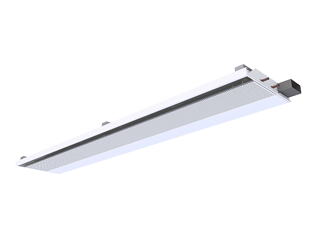
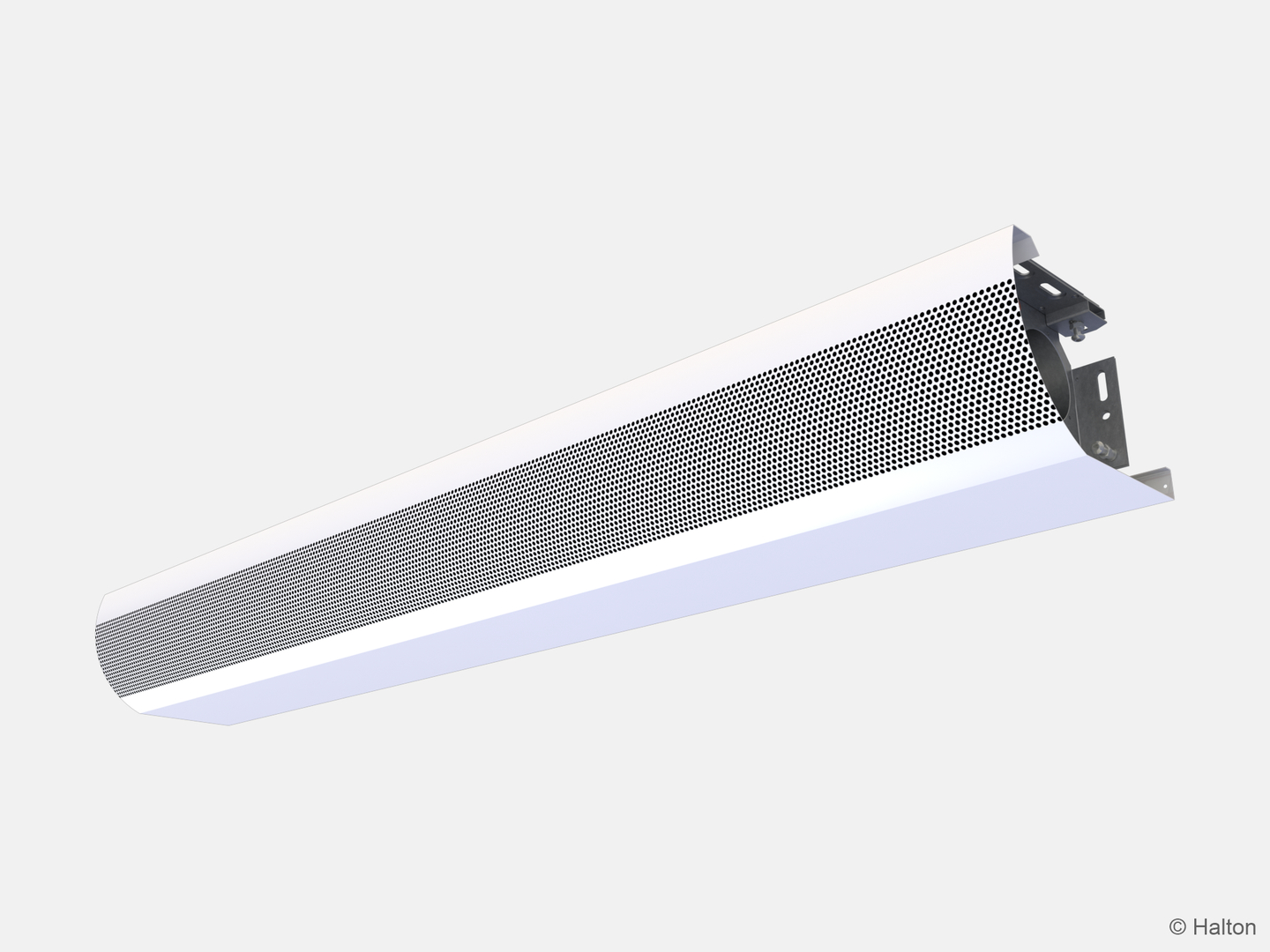
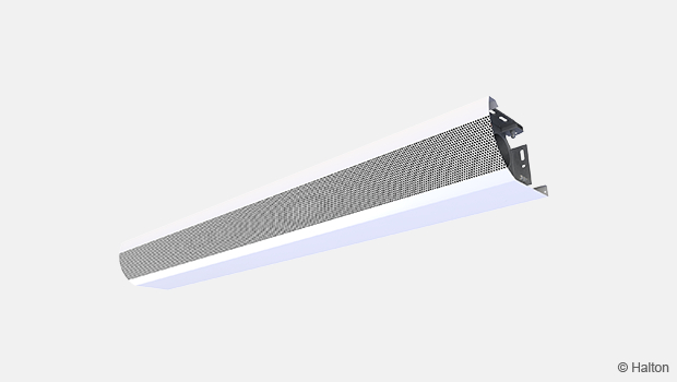
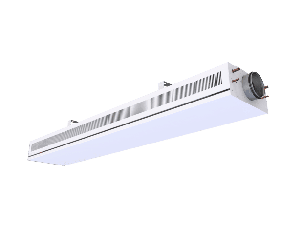
NEW! Halton Rex RSI – Slim induction unit
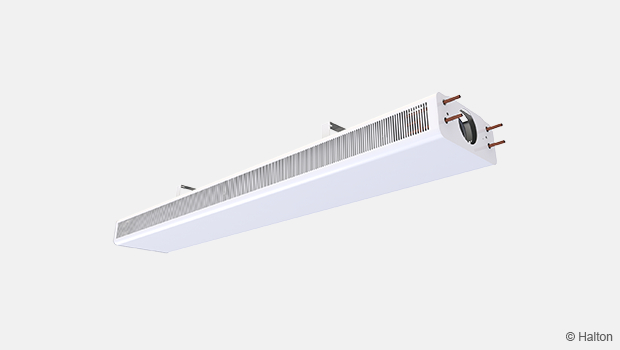
Halton’s ultra-slim chilled beam unit, with a profile of only 80 mm height, enables a disruptive layout that requires one-third fewer units compared to traditional systems.
Its compact design allows for a shorter floor-to-floor height, creating either more usable space within rooms or additional floors in the building. It enhances occupant comfort while offering greater design flexibility. Furthermore, lowers lifecycle costs and environmental impact by reducing workspace churn, optimising indoor climate efficiency, and supporting sustainable building operations, making it an efficient and cost-effective choice for modern buildings.
- Ideal for integration with radiant panels and for installation in renovation projects
- Available with smart, demand-based controls and with project-specific tailoring
Overview
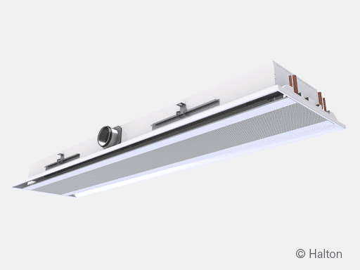
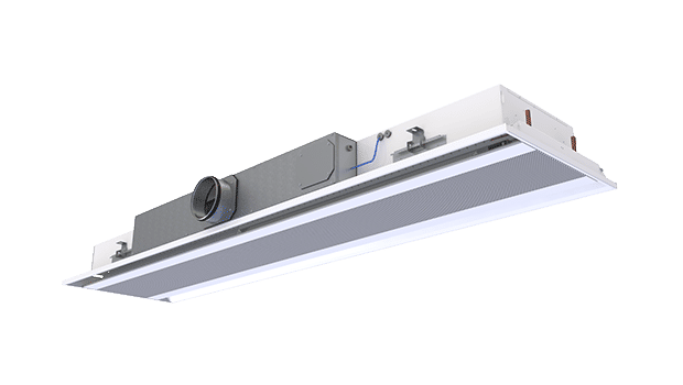
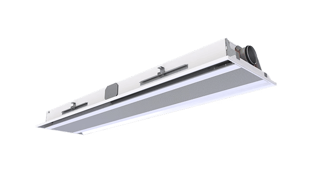
The Halton Rex RSI, an ultra-slim induction unit/chilled beam, is designed to meet demanding space-height and layout-flexibility requirements. Ideal for integration with radiant panels and for installation in renovation projects when a very low height is appreciated. The Halton Rex RSI can be equipped with smart, demand-based controls, minimising energy consumption by responding in real time to occupancy, CO2 levels, and temperature. Its modular, serviceable design features two independent unidirectional induction units that deliver fresh, conditioned air while reducing unnecessary airflow and energy waste.
Ideal for transient and flexible office environments, this system significantly lowers lifecycle costs and environmental impact by reducing workspace churn, optimising indoor climate efficiency, and supporting sustainable building operations.
Application areas
- Office rooms
- Public spaces
- Open offices and meeting rooms
Key features
- Easy and fast selection with Halton HIT Design tool
- Individually adjustable velocity conditions with Halton Velocity Control (HVC)
- In-built flexibility of operation for partition wall relocations with Halton Velocity Control (HVC)
- Available with smart, demand-based controls and with project-specific tailoring
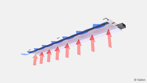
Operating principle
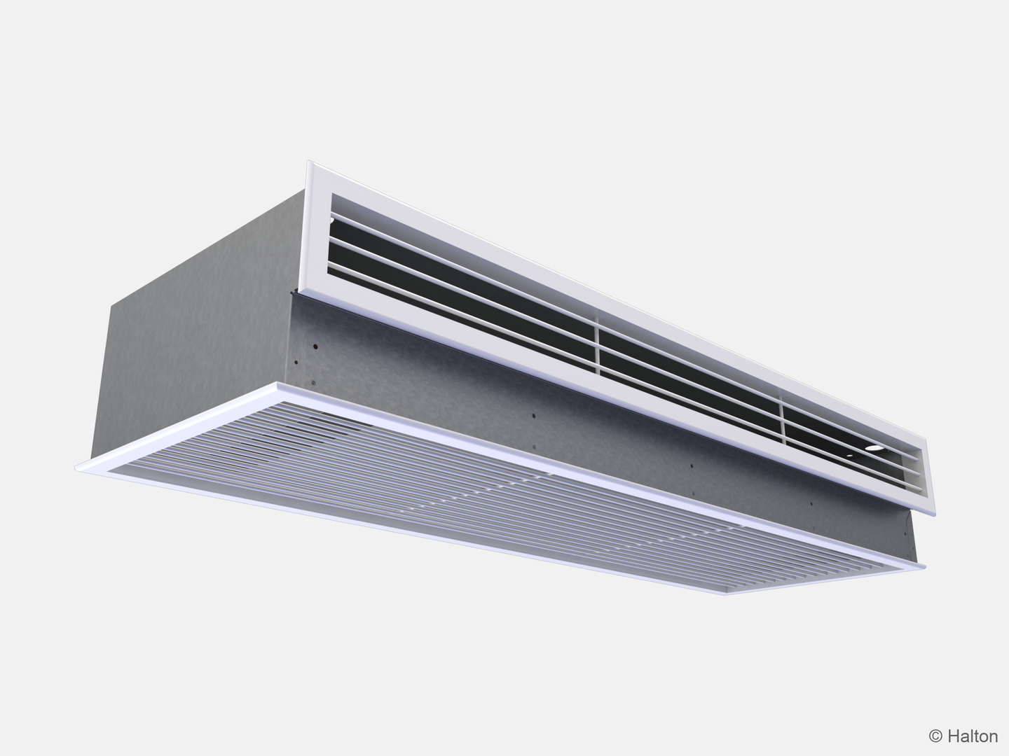
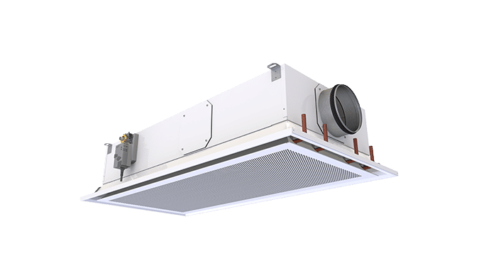
The Halton Rex RSI slim induction unit is designed to be installed flush with a suspended ceiling.
The unit operates on the principle of induction, where primary air is forced through nozzles (blue arrows in the figure below), creating a low-pressure area that draws in (or induces) secondary air from the room (red arrows in the figure below). This induced air then passes over a heat exchanger (typically a water coil) where it is cooled, before being mixed with the primary air and discharged into the room through precision-engineered nozzles. This process provides ventilation and cooling while minimising fan energy consumption.
As the high-velocity supply air exits the nozzles, it generates jets that effectively induce ambient room air into the unit. The built-in heat exchanger then conditions this induced air as required. The resulting mixed airflow is discharged horizontally along the ceiling surface, enhancing air circulation and ensuring uniform thermal comfort throughout the space.
Velocity control in the occupied zone
The Halton Velocity Control (HVC) is used to adjust room air velocity conditions either when the room layout is changed, (e.g., in cases where the chilled beam is located near the partition wall) or when local, alter the individual velocity conditions. The HVC adjustment impacts the induced room airflow through the heat exchanger. Therefore, it either increases or decreases both the velocities in the occupied zone and the cooling/heating capacity of the chilled beam.
The HVC involves manual velocity adjustment in three different positions. Position 3 provides the highest cooling capacity, position 2 a bit lower cooling capacity and position 1 throttles most the cooling capacity and velocities in the occupied zone. The HVC element is divided into sections to enable the adjustment of conditions in different parts of the occupied zone. Depending on the length of the beam, the optimal HVC damper module lengths are between 500 and 1400 mm.
Airflow rate control
The supply airflow of the chilled beam nozzle jets are dependent on effective length (heat exchanger) and static chamber pressure, which can be adjusted e.g. using separate airflow adjustment damper in the duct.
Chilled beam can be equipped with three different nozzle types: D (smallest airflow), E (medium airflow), or DE with both nozzles D and E (highest airflow). Selected nozzle provides the needed supply airflow rate at the design duct pressure level. With selected cooling water parameters the chilled beam delivers requested cooling capacity via the supply air and via cooling water heat exchange with the induction air.
Manual control type (CN=MA) includes openable nozzles. This function is used for adjusting the outdoor airflow rate in a room space. The airflow rate is dependent on the opening position of nozzles and the static chamber pressure. Airflow rate adjustment is needed when the use of the space is changed and the demand of conditions need to meet the supply airflows. Airflow rate can be adjusted manually with selecting nozzle D (smallest airflow), E (medium airflow), or DE with both nozzles D and E (highest airflow).
Features and options
| Category | Option | Feature | Description |
|---|---|---|---|
| Cooling coil | TC = C | Coil with cooling water circulation | Cooling copper water pipe connections are Ø 12 mm. |
| Nozzles | CN = NA |
Fixed |
Fixed nozzles based on selection between: D (Large), E (Extra large), and a pair of D+E (largest nozzle option). |
| CN = MA | Manual | Openable nozzles with manual control based on project-specific needs. |
|
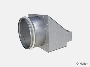
| Connection package | CP = R1 | Right (110 x 50/125) | Duct connection adapter from rectangular to circular. |
| CP = L1 | Left (110 x 50/125) | Duct connection adapter from rectangular to circular. |
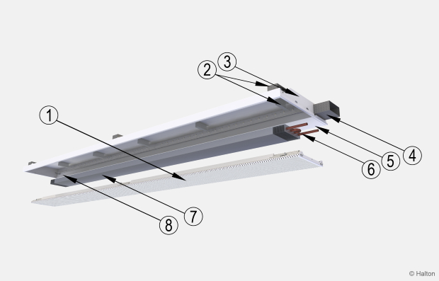
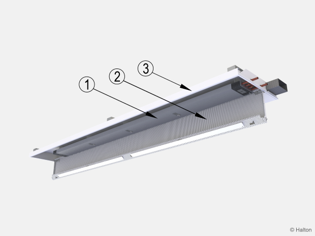
Structure and materials
| No. | Part | Material | Description | Note |
|---|---|---|---|---|
| 1 | Front panel | Galvanised steel | Polyester-pre-painted galvanised steel, white (RAL 9003, 20% gloss) | Special colours available |
| 2 | Brackets | Galvanised steel | – | – |
| 3 | End plates | Galvanised steel | Pre-painted galvanised steel, Polyester-painted, white (RAL 9003, 20% gloss) | Special colours available |
| 4 | Supply air | Galvanised steel | – | – |
| 5 | Casing | Galvanised steel | Pre-painted galvanised steel, Polyester-painted, white (RAL 9003, 20% gloss) | – |
| 6 | Coil pipes | Copper | – | – |
| 7 | Coil/Heat exchanger | Pipes-copper, Fins-aluminium | Pipes and fins | – |
| 8 | Pressure measurement tube | Polyvinyl chloride | – | – |
Cooling water pipe connections are Cu15/Cu12 with wall thickness of 0.9-1.0 mm fulfilling European Standard EN 1057:1996.
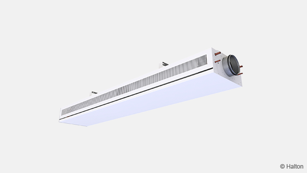
The maximum chilled/hot water circuit operating pressure is 1.0 MPa. The supply air duct connection is rectangular 110×50 mm, with an optional duct connection adaptor for circular 125 mm.
Dimensions and weight
| ØD | Coil length [mm] | Length L [mm] | Weight [kg/m, water excluded] |
|---|---|---|---|
| 125 | 900, +300, …, 3300 | 1200, +300, …, 3600 |
20.5 |
Specification
Ultra-slim induction unit/active chilled beam with CAV/VAV airflow function and one-directional air distribution, used for cooling and ventilation in suspended ceilings, fulfilling the following requirements:
Function
- The beam can be equipped with a manual actuator for demand-based control of the airflow adjustment.
- The air supply to the room space is uni-directional.
Structure
- The front panel is openable from either side in order to allow general maintenance and cleaning.
- The front panel is removable without any special tools.
- Fixed nozzles or equipped with a manual changeable nozzles.
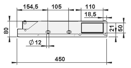
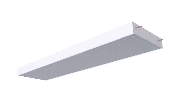
- The chilled beam is 80 mm high and 450 mm wide, with air inlet dimensions of 110 x 50 mm.
- The beam air inlet is connected to a spigot duct with Ø125 mm with optional duct connection adaptor from rectangular to circular.
- Two Ø12 mm connection pipes shall incorporate cooling water within the heat exchanger.
- The maximum operating pressure of the pipework is 1.0 MPa @ 70 °C.
Material
- The frame, the front, and the side panels are of galvanised steel plates.
- All visible parts shall be white and painted to RAL 9003 (20% gloss).
- All water pipes are made of copper and connection pipes with a wall thickness of 0.9-1.0 mm.
- The fins are made of aluminium.
Packaging and transport
- Each chilled beam is identifiable by a serial number printed on a label attached to the chilled beam.
- Labels attached to both the unit and the plastic packaging shall identify the beams.
- The duct connection and pipe ends shall remain sealed during transport.
Installation
The Halton Rex RSI slim induction unit is suitable for suspended ceiling mounting. When selecting of the chilled beam orientation, the location of the supply air and water circuit connections are taken into account.
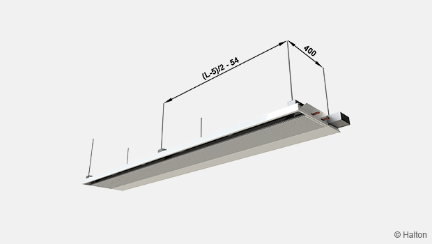
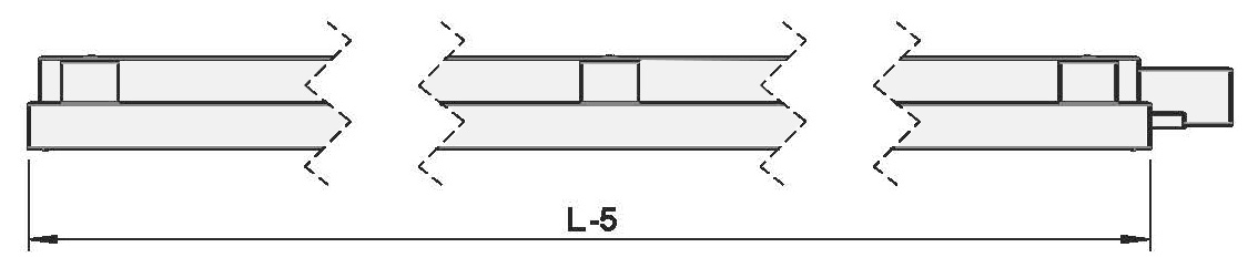
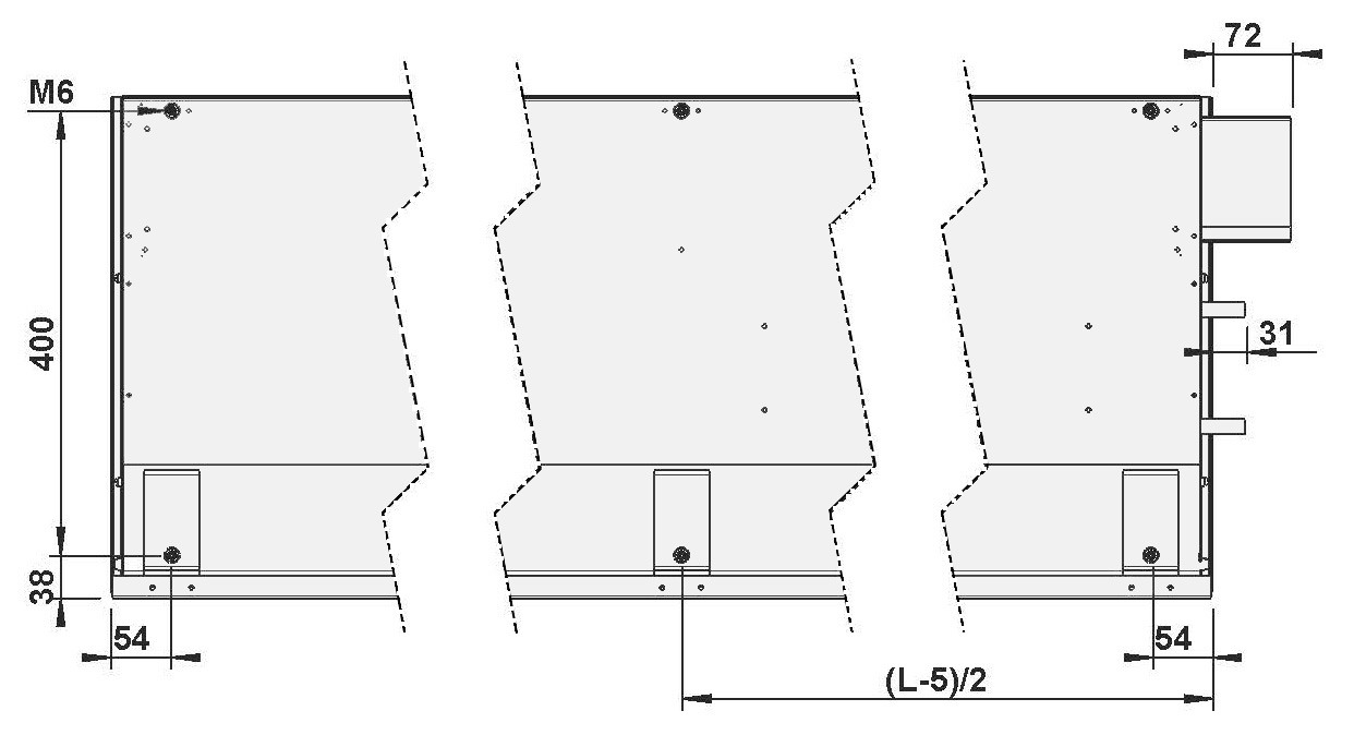
The chilled beam can be attached directly to the ceiling surface (H1 = 80 mm) or suspended using threaded drop rods (8 mm). Each beam is equipped with movable brackets fixed to both sides of the beam. It is recommended that the brackets be positioned one quarter of the unit length (L/4) away from the end of the beam.
Install the main pipelines of the cooling water circuits above the level of the chilled beam in order to enable venting of the pipework.
The duct connection is at the same end of the chilled beam as the pipe connections.
Commissioning
Cooling
The recommended cooling water mass flow rate is 0.02 – 0.10 kg/s, resulting in a temperature rise of 1 – 4 °C in the heat exchanger. To avoid condensation, the recommended inlet water temperature of the heat exchanger is 14 – 16 °C.
Balancing and control of water flow rates
Balance the water flow rates of the chilled beam with adjustment valves installed on the outlet side of the cooling and/or heating water loops. The cooling capacity and/or heating capacity of the chilled beam are controlled by regulating the water mass flow rate. The water mass flow rate can be controlled by using an ON/OFF valve or a two- or three-way proportional valve.
Adjustment of supply airflow rate
Connect a manometer in the measurement tap and measure the static pressure in the chilled beam. The airflow rate is calculated according to the formula below.
Total airflow rate (q v )

|
qv |
Total airflow rate, l/s or m3/h |
| k | k-factor (from table below) |
|
leff |
Length of the coil [mm] |
|
Δ pm |
Measured static chamber pressure [Pa] |
| Nozzle | k [l/s] | k [m3/h] |
|---|---|---|
| D | 0.59 | 2.12 |
| E | 0.94 | 3.38 |
| D+E | 1.52 | 5.47 |
Maintenance
| No. | Parts |
|---|---|
| 1 | Heat exchanger |
| 2 | Front panel |
| 3 | Side plates |
Always disconnect the chilled beam from the water supply before performing any maintenance. Ensure the unit is not in operation and the surrounding area is safe for work. No special tools are required to open the unit. The panels are designed for easy access.
As the beam is only openable from the outside, gently pull the lever (loaded with the hinge pin) on either side of the panel so the pin withdraws from the hole, releasing the front panel.
Open the front panel of the supply air chamber, the ductwork, and the heat exchanger. Clean the supply air chamber and finned coils of the heat exchanger using a soft brush or a vacuum cleaner, taking care not to bend or damage the finned coils.
Clean the front panel and, if required, the side plates using a damp cloth. Check nozzle integrity and water connections during scheduled maintenance.
Order code
RSI-S-L-E; SP-TC-CN-CP-CO-ZT
| Main options | |
|---|---|
| S = Nozzle type | |
| D | Large |
| E | Extra Large |
| DE | Large + Extra large pair |
| L = Beam length [mm] | 1200, 1500, 1800, 2100, 2400, 3000, 3600 |
| E = Duct connection [mm] | |
| R1 | Right (110×50) |
| L1 | Left (110×50) |
| Other options and accessories | |
|---|---|
| SP = System package | |
| N | No |
| Y | Yes |
| TC = Cooling/Heating functions (coil type) | |
| C | Cooling |
| CN = Control type | |
| NA | Not assigned |
| MA | Manual |
| CP = Connection package | |
| NA | Not assigned |
| R1 | Right (110×50/125) |
| L1 | Left (110×50/125) |
| CO = Colour | |
| SW | Signal white (RAL 9003) |
| X | Special colour (RAL xxxx) |
| ZT = Tailored product | |
| Y | Yes (ETO) |
Order code example
RSI-D-2400-R1; SP=N, TC=C, CN=MA, CP=R1, CO=SW, ZT=Y
Downloads
"*" indicates required fields
Halton CaBeam – Chilled beam for exposed wall installation
product
Halton CaBeam – Chilled beam for integrated installation
product
Halton CaBeam – Chilled beam for recessed installation
product
Halton CBH – Chilled beam
product
Halton CHB – Chilled beam
product
Halton CPA – Passive chilled beam
product
Halton CSW – Swirl comfort unit
product
Halton Rex R6W – Variable air volume chilled beam (VAV)
product
Halton Rex RE6 – Chilled beam
product
Halton Rex REE – Chilled beam
product
Halton Rex REO – Chilled beam (VAV)
product
Halton Rex REW – VAV chilled beam
product
Halton Rex RXP – Chilled beam (CAV/VAV)
product

Halton Vita VPR – Hygienic chilled beam
product
NEW! Halton Rex REP – Passive chilled beam
product
NEW! Halton Rex RSI – Slim induction unit
product