Product / FDI
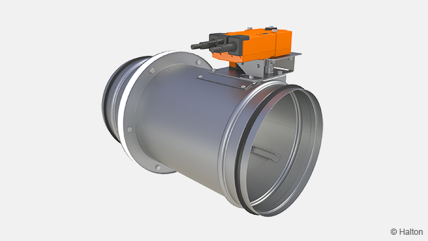
Halton FDI – Fire damper (EI 60 S)
This CE marked, already well known fire damper is a familiar member of our Fire safety family. Fire resistance class is provided up to EI 60 S requirements.
- Sizes available from 100 mm up to 630 mm
- Double sealing on the blade to ensure full tightness
Overview
- CE marked according to the product standard EN15650:2010 and tested according to the fire test standard EN 1366-2
- External quality control management by Eurofins Expert Services Oy
- Fire resistance class: EI 60 (ve ho i <-> o) S and E 90 (ho i <-> o) S
- Installation on the wall with shaft oriented horizontal or vertical
- Declaration of Performance 10002-FDI-2016/01/01
- Approved for installation in concrete, masonry and flexible (gypsum board or similar) walls and ceilings between the fire compartments
- Double sealing on the blade to ensure the tightness class 4 according to EN 1751
- Casing tightness class C according to EN 1751
- Damper closing test performed at 15 m/s duct velocity
- Suitability for use in ducts with a maximum pressure of 3300 Pa
- Installation in circular ventilation ducts of 100…630 mm
- With electrical actuator or mechanical spring release
Accessories
- Safety mesh
- Limit switches for mechanical spring release
- Factory made pre fire break grouting
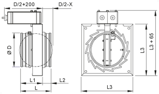
Dimensions and weight
Electric actuator (OP=N1, N2)
| NS [mm] |
ØD [mm] |
L [mm] |
L1 [mm] |
L2 [mm] |
L3 [mm] |
X [mm] |
| 100 | 99 | 145 | 105 | 40 | 183 | 40 |
| 125 | 124 | 145 | 105 | 40 | 208 | 40 |
| 160 | 159 | 145 | 105 | 40 | 242 | 40 |
| 200 | 199 | 145 | 105 | 40 | 283 | 40 |
| 250 | 249 | 145 | 105 | 40 | 333 | 40 |
| 315 | 314 | 145 | 105 | 40 | 398 | 40 |
| 400 | 399 | 245 | 135 | 110 | 480 | 100 |
| 500 | 499 | 245 | 135 | 110 | 580 | 100 |
| 630 | 629 | 245 | 135 | 110 | 710 | 100 |
The size of the installation hole is ØD + 20 mm
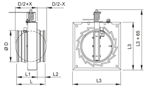
Mechanical actuator (OP= MA)
Detailed installation instructions, as well as an installer’s installation certificate form can be found from QR code on product label.
For further information see section Downloads/Installation instructions.
Weight [kg]
| NS [mm] |
MA | MO | MA + FB | MO + FB |
| 100 | 1.1 | 2.5 | 2.0 | 3.5 |
| 125 | 1.3 | 2.7 | 2.5 | 3.9 |
| 160 | 1.7 | 3.2 | 3.2 | 4.6 |
| 200 | 2.2 | 3.6 | 4.1 | 6.4 |
| 250 | 3.1 | 4.5 | 5.40 | 6.9 |
| 315 | 4.2 | 5.6 | 7.3 | 8.7 |
| 400 | 6.8 | 8.3 | 10.2 | 11.7 |
| 500 | 9.5 | 11.0 | 14.0 | 15.4 |
| 630 | 14.1 | 15.5 | 20.1 | 21.6 |
MA = Mechanical actuator MO = Electric actuator FB = Factory made prefire mastic
Quantity of fire break mastic
| GBG | WÜRTH | HILTI | ||
| NS | liter/size/order | kg/size/order | kg/size/order | kg/size/order |
| 100 | 1.2 | 1.0 | 1.0 | 1.2 |
| 125 | 1.5 | 1.2 | 1.2 | 1.5 |
| 160 | 1.9 | 1.5 | 1.5 | 1.9 |
| 200 | 2.4 | 1.9 | 1.9 | 2.4 |
| 250 | 3.0 | 2.4 | 2.4 | 3.0 |
| 315 | 4.0 | 3.1 | 3.1 | 4.0 |
| 400 | 4.3 | 3.4 | 3.4 | 4.3 |
| 500 | 5.6 | 4.5 | 4.5 | 5.6 |
| 630 | 7.6 | 6.1 | 6.1 | 7.6 |
| GBG | WÜRTH | HILTI | |
| kg/sack | 20 | 10 | 20 |
| liter/sack | 25 | 12 | 20 |
Material
| Part | Material |
| Casing | Galvanised steel |
| Blade | Galvanised steel/Heat-insulating panel structure |
| Blade gasket | Silicone |
| Expanding seal | Graphite mass |
| Closing spring (mechanical actuator) | Stainless steel |
| Fuse (mechanical actuator) | Brass |
| Duct gaskets | 1C-polyurethane hybrid |
| Factory made pre fire break grouting | Sealfire W1000 (Würth) |
Operating models and accessories
| Accessory | Code | Description | Electric actuator |
Mechanical actuator |
| Safety mesh on one side | N1 | Galvanised steel (10×10 mm) Installed on actuator side |
X | X |
| Safefty mesh on two sides | N2 | Galvanised steel (10×10 mm) | X | X |
| Fuse | FU | Thermal release at 72 ºC | – | X |
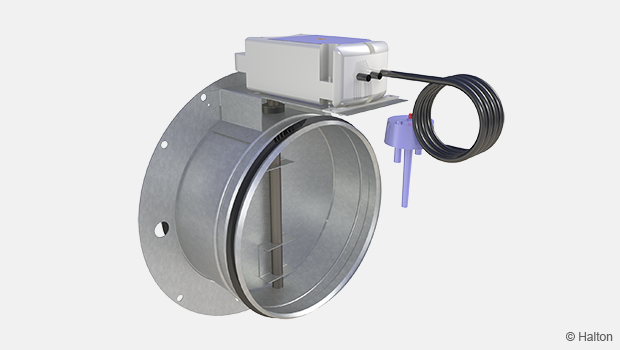
| Limit switch (1 pc) | LS1 | Closed position indication, enclosure class IP65 (Fig.2) |
– | X |
| Limit switches (2 pcs) | LS2 | Open/closed position indication, enclosure class IP 65 (Fig.3.) |
– | X |
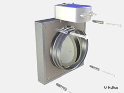
| Factory (Halton) made pre fire break grouting |
FB | Sealfire W1000 (Würth) | X | X |
Note!
The Halton FDI fire damper’s CE approval is valid when the installation flange filled to the edges with fire prevention mastic on site. For futher information, see tab Documents / Installation.
The CE approval is also valid when the fire break grouting is made by Halton factory for Halton FDI fire damper installation flange (FB).
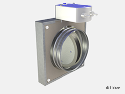
Fig.1. Factory made pre fire break grouting (FB)
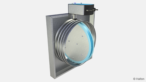
Electric actuator (N1, N2)
In the electric actuator system when a signal from building automation reaches the actuator or the fuse reacts to a rise in temperature (72 °C) power is switched off and the spring closes the blade of the damper. When the supply power is turned back on (e.g. during routine testing), the actuator opens the blade. In case of a power failure, the mechanical spring of the actuator ensures the failsafe function by closing the blade. The actuator is equipped with built-in limit switches for both open and closed position and have a visual position indicator.
The fuse can be replaced from outside the device.
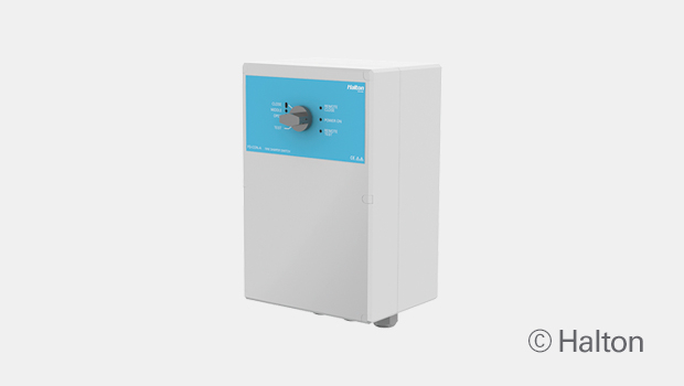
The Halton FDI fire damper with 24V power supply is recommended to be connected to the Halton Safe Management 2.0 (SM2) fire and smoke safety control system. This system enables the use of smoke detectors in ductwork or room spaces. The Halton FDI fire damper can also be connected to other commonly used building automation systems.
Actuator options
N1 GNA126.1E/T12 (72 °C), 24 V, 7 Nm, with limit switch
N2 GNA326.1E/T12 (72 °C), 230 V, 7 Nm, with limit switch
Mechanical spring release, failsafe (MA)
The fuse reacts to the rise of temperature (72 ºC) and the spring closes the blade. It needs to be opened manually.
This operating model has a visual position indicator and fuses can be replaced from outside the device.
Limit switch (LS1, LS2)
The limit switch (accessory) indicates the position of the damper blade. When it is open (safe position), the limit switch indicates this position. If the damper blade is closed (failsafe), the limit switch sends an impulse to the monitoring system. This system triggers an alarm and/or stops/starts fans, depending on the designed system. The limit switch has no influence on the thermal fuse or release mechanism.
The maximum operating voltage and current is 400 V, 10 A.
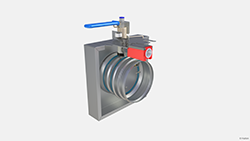
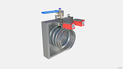
Fig.2. With one limit switch (LS1) Fig.3. With two limit switches (LS2)
Function
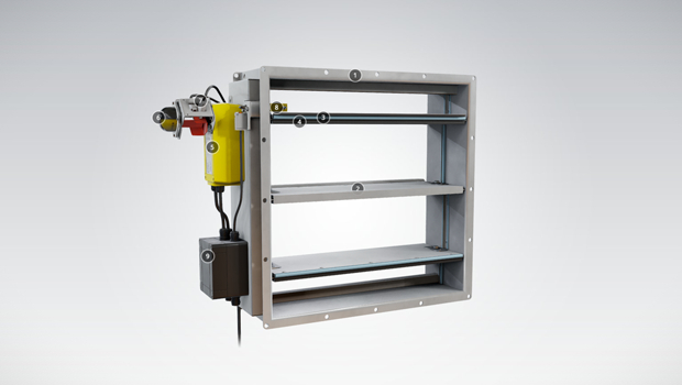
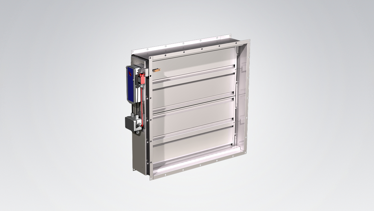
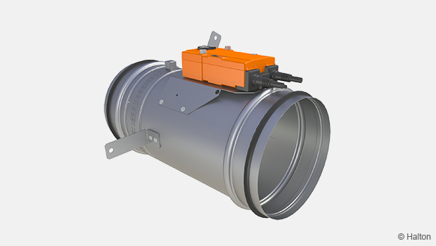
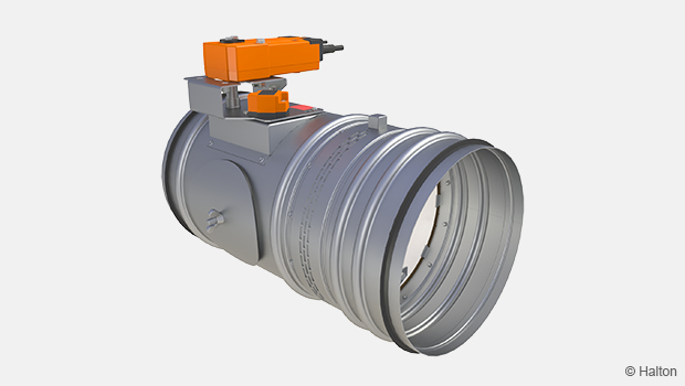
The Halton FDI is a circular fire damper, which prevents fire and smoke from spreading in the ductwork of ventilation systems between fire compartments.
The Halton FDI is approved for vertical (ve) and horizontal (ho) installation in heavy and light-weight structures fulfilling the fire resistance class EI 60 (ve ho i <-> o) S requirements. It is also approved for horizontal (ho) installation in concrete floors/ceilings to fulfill the fire resistance class E 90 (ho i <-> o) S requirements.
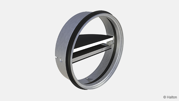
The fire damper is made of fireproof materials. Once the fire damper has closed, the double sealing closes the duct tightly, effectively preventing the spread of fire gases through the ventilation ductwork. The flexible silicone seal is tightening the blade at lower temperatures, while the graphite mass seal expands to insulate the system at temperatures above 150 ºC.
The fire damper is equipped with either electric (supply power 24V or 230V) or mechanical actuator (failsafe). All models are also equipped with a thermal fuse and a visual position indicator.
For further information, see section Operating models.
Installation
The Halton FDI fire damper is installed on concrete or masonry walls and ceilings and on lightweight walls.
See installation video from link below:
Halton FDI installation
An opening is always left in the separating element for the casing of the product to be led through the structure. The maximum diameter of the installation hole is the fire damper diameter D + 20 mm.
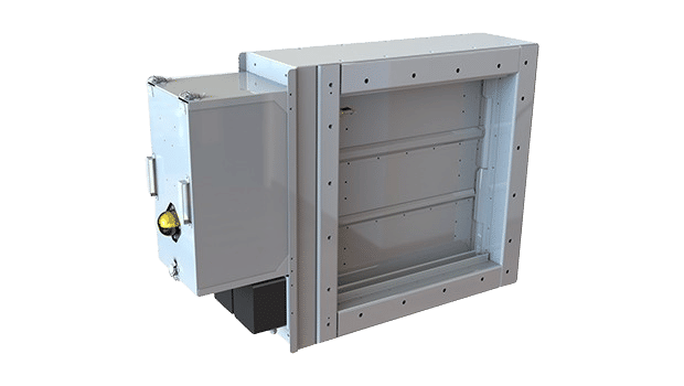
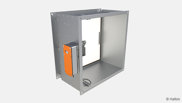
To make installation easier, all products come with an installation/casting frame, which is used to fasten the fire damper to the wall surface or the steel frame of the plasterboard wall.
The installation is finished by filling the casting frame from the front of the device with a gypsum-based firestop certificated fire break compound that is tested for use for this purpose (GBG from Palokatkomiehet Oy; CP 637 from Hilti; or FIREBREAK COMPOUND from Würth). During installation, the fire damper and actuator must be protected with, e.g. a plastic cover.
When the Halton FDI fire damper has a factory made pre fire break grouting (AC=FB), it can be installed to a lightweight panel walls by using four suitable screws to a steel frame or a wooden joist (see pictures below). The fire damper can be installed to the masonry structures by using four 8 mm steel wedge anchor.
The correct operation of the fire damper must be ensured both before and after grouting. Setting of the damper is performed from outside the device.
Detailed installation instructions, as well as an installer’s installation certificate form, are supplied with each product. See also the Documents / Installation Instructions.
Electric actuator wiring diagram (Siemens)
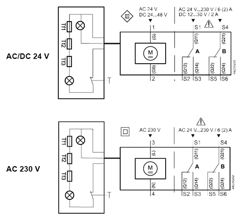
Mechanical actuator wiring diagram with limit switch (AC=LS1 or LS2)
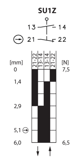

The manual fire damper can be equipped with a bipolar limit switch (LS1, LS2) which indicates the closing of the shutoff blade. The limit switch has potential-free points, which can be used to control other fire dampers equipped with an electric release, e.g., triggering an alarm in the fire suppression system. The maximum operating voltage and current is 400 V, 10 A.
Servicing
If the blade of the manual fire damper does stay open, the fuse must be replaced. The fuse can be changed from outside the fire damper.
The fuse of a fire damper equipped with an electric actuator must be replaced if the fuse has been released because of a rise in temperature in the duct.
To ensure proper operation of fire dampers, they should be inspected regularly. The minimum recommended inspection period is every 6 months or according to the building code. It is recommended that the fire damper is connected to automatic fire damper management system Halton Safe Management 2.0 (SM2), operating voltage 24-VAC.
Upon failure during testing of the fire damper, maintenance service shall be ordered from an authorised Halton representative to ensure appropriate operation of the product.
Specification
The fire damper is CE marked according to the standard 15650:2010 and tested according to the test standard EN 1366-2.
A fire damper of fire resistance class EI 60 (ve,ho,i<->o) S and in concrete ceilings also E 90 (ho,i<->o) S, has a double-sealing solution that ensures fire-gas tightness and fire resistance both at room temperature and in high temperatures when the fire damper is closed.
In models with electrical actuator, the fuse shall be activated at 72 °C.
In the mechanical spring release model, the fuse activation temperature corresponds to the specifications (72 °C).
The fuse is located inside the damper, and it is possible to replace it from the outside.
The fire damper has means for external opening / triggering of the release and closing.
The fire damper includes a position indicator.
The fire damper casing complies with the tightness requirements for EN 1751 class C.
The fire damper is suitable for vertical and horizontal installation in concrete and masonry walls and on ceilings and lightweight plasterboard walls between fire compartments.
The blade shaft can be installed in either horisontal or vertical orientation, and the actuator can be installed in any direction.
The fire damper can be installed from the installation frame side without separate sealing of the installation opening on the wall.
The internal quality control of the fire damper manufacturer is based on the ISO 9001 quality system, and the operations of the manufacturer shall be subject to external third-party quality control.
Order code
FDI-D, OP-FU-FB-AC-ZT
| Main options | |
| D = Duct connection size [mm] | 100, 125, 160, 200, 250, 315, 400, 500, 630 |
| Other options and accessories | |
| OP = Operating model | |
| N1 | GNA126.1E/T12 (72 °C) 24 V, 7 Nm |
| N2 | GNA326.1E/T12 (72 °C) 230 V, 7 Nm |
| MA | Mechanical spring release (failsafe) |
| FU = Fuse release temperature [°C] | |
| 72 | 72 °C |
| FB = Factory made fire break grouting | |
| N | No |
| Y | Yes |
| AC = Accessories | |
| N1 | Safety mesh, 1 side (installed on actuator side) |
| N2 | Safety mesh, 2 sides |
| LS1 | Limit switch (closed position) |
| LS2 | Limit switch (open/closed position) |
| ZT = Taylored product | |
| N | No |
| Y | Yes (ETO) |
Order code example
FDI-500, OP=N1, FU=72, FB=N, AC=N2, ZT=N
Downloads
-
Halton FDI – Fire damper (EI 60 S)
Data
en
-
Halton FDI – Palopelti (EI 60 S)
Data
fi
-
Halton FDI – Brand-/Brandgasspjäll (EI 60 S)
Data
se
-
Installation instructions – Halton FDI
Data
e -
Asennusohje – Halton FDI
Data
Suomi (fi) -
Declaration of Performance (DoP) – Halton FDI
Data
English (en) -
Suoritustasoilmoitus (DoP) – Halton FDI
Data
Suomi (fi) -
Prestandadeklaration (DoP) – FDI
Data
sv_SE -
Construction Product Regulation (CPR) – Fire dampers
Data
English (en) -
Palo- ja savunhallintapeltien asennustodistus
Data
Suomi (fi) -
Installation Certificate for Fire Dampers (used in UK)
Data
English (en)
"*" indicates required fields
CFD-01 – A0 (A60) E120S Fire damper
product
CFD-02TM – High temperature tunnel damper
product
FCE – Fire damper (EI 60 S)
product

FD-CON-2 – Fire damper control unit
product
FD-CON-A – Fire damper control unit
product

FDA – A0(A60) Fire and gas damper
product
FDB2 – A0(A60) Fire and gas damper
product
FDH – H0(H120) Fire and gas damper
product
FDK – A0(A60) Fire damper
product
FDL – A0(A60) Fire damper
product
FDO – A0(A60) Fire and gas damper
product
Halton Exe EDC – Fire damper (EI 120 S)
product
Halton Exe EFC – Fire damper (EI 120 S)
product
Halton Exe ELC – Fire damper (E 120 S)
product
Halton Exe ELR – Fire damper (E 120 S)
product
Halton Exe ESC – Fire damper (EI 120 S)
product
Halton Exe ESR – Fire damper (EI 120 S)
product
Halton Exe ETC – Fire damper (EI 120 S)
product

Halton Exe ETR – Fire damper (EI 120 S)
product
Halton FDI – Fire damper (EI 60 S)
product