
Product / RDR
Halton RDR – Adjustable airflow regulator
Halton RDR is a compact device designed for in‑duct airflow regulation. It maintains consistent airflow automatically within a defined pressure range.
- Suitable for supply and extract air systems
- Pressure‑independent operation, no external control required
- Acoustic performance defined by sound power level Lw (dB(A))

Overview
The Halton RDR adjustable airflow regulator is an in‑duct airflow management element designed to maintain a constant airflow within a defined pressure range. It is suitable for ventilation and air‑conditioning systems for both supply and extract air and is installed directly inside circular ductwork.
Application areas
- Commercial and public buildings
- Office buildings, schools and healthcare facilities
Key features
- Maintains constant airflow independently of duct pressure fluctuations
- Adjustable airflow setting with clear scale and locking mechanism
- Suitable for both supply and extract air applications
- Compact design for direct installation inside circular ducts
- Factory calibrated regulating mechanism
Operating principle
The regulator maintains a constant airflow by means of an internal regulating element that reacts to pressure changes in the duct. Within a pressure range of 50–250 Pa, the regulating element automatically adjusts its position to keep the airflow at the preset value.
The airflow is set using an adjustable airflow module, which can be locked after setting to prevent unintentional changes.
Structure and materials

| No. | Part | Material | Note |
|---|---|---|---|
| 1 | Sleeve with seal | M1-classified plastic | – |
| 2 | Spacer | – | According to the airflow |
| 3 | Casing | Plastic | – |
| 4 | Regulating element | Plastic | – |
| 5 | Lock screw | – | Screw to fix the airflow |
| 6 | Flow control module | – | – |
Dimensions

| Size | L | D1 | D2 |
|---|---|---|---|
| Ø100 | 68 | 96 | 93 |
| Ø125 | 68 | 120 | 60 |

| Size | L1 | L2 | D1 | D2 |
|---|---|---|---|---|
| Ø125 | 80 | 86 | 120 | 117 |
| Ø160 | 78 | 85 | 148 | 148 |
| Ø200 | 82 | 91 | 195 | 195 |
| Ø250 | 82 | 120 | 244 | 245 |
The Halton RDR configuration depends on the selected airflow rate. Consequently, different airflow ranges apply for the same diameter. See table below.
| Size | Setting | Flow [m3/h] | Set flow [m3/h] |
|---|---|---|---|
| Ø100 | RDR Ø80 + 1 spacer | 15 to 50 | 50 |
| RDR Ø100 | 50 to 100 | 100 | |
| Ø125 | RDR Ø80 + 1 spacer* | 15 to 50 | 50 |
| RDR Ø100 + 1 spacer | 50 to 100 | 100 | |
| RDR Ø125 | 100 to 180 | 180 | |
| Ø160 | RDR Ø80 + 2 spacers* | 15 to 50 | 50 |
| RDR Ø100 + 2 spacers | 50 to 100 | 100 | |
| RDR Ø125 + 1 spacer | 100 to 180 | 180 | |
| RDR Ø160 | 180 to 300 | 300 | |
| Ø200 | RDR Ø80 + 3 spacers* | 15 to 50 | 50 |
| RDR Ø100 + 3 spacers | 50 to 100 | 100 | |
| RDR Ø125 + 2 spacers | 100 to 180 | 180 | |
| RDR Ø160 + 1 spacer | 180 to 300 | 300 | |
| RDR Ø200 | 300 to 500 | 500 | |
| Ø250 | RDR Ø100 + 4 spacers | 50 to 100 | 100 |
| RDR Ø125 + 3 spacers | 100 to 180 | 180 | |
| RDR Ø160 + 2 spacers | 180 to 300 | 300 | |
| RDR Ø200 + 1 spacer | 300 to 500 | 500 | |
| RDR Ø250 | 450 to 700 | 800 |
* Consisting of a double spacer.
Specification
The Halton RDR adjustable airflow regulator is designed for in-duct installation to ensure stable and predefined airflow rates over a wide pressure range.
Materials
- The sleeve is made of M1‑classified plastic.
- The casing and regulation module is made of plastic.
Structure
- Provides constant airflow within a pressure range from 50–250 Pa.
- The maximum operating temperature is 60 °C.
- Airtightness is ensured by an integrated sealing gasket.
- Available duct diameters are Ø100, Ø125, Ø160, Ø200, and Ø250.
- Airflow tolerance is ±3 m³/h for airflow ≤50 m3/h and ±5% for airflow >50 m3/h.
- Sound power levels (Lw) are expressed in dB(A) and depend on airflow and pressure.
Installation
- Installed by direct insertion into horizontal or vertical ducts.
- In horizontal duct installation, the DOWN marking on the regulator must be observed.
- The airflow direction marked on the sleeve must always be followed.
- A leak seal ensures an airtight connection without additional sealing.
- Minimum distance to air terminal device:
- Extract air: at least 1Ø.
- Supply air: at least 3Ø.
- Do not press or manipulate the regulating element during installation.


Commissioning
Airflow must be calibrated before installation.
- Loosen the locking screw of the adjustment module by 1/4 turn using a torx n°10 screwdriver
- Align the indicator with the required airflow value
- Retighten the locking screw to secure the setting


Maintenance
- The airflow regulator must remain accessible at all times
- Accessibility is required to allow inspection, verification, and maintenance of the airflow setting
Order code
RDR-D
| Main options | |
|---|---|
| D = Duct connection diameter [mm] | 100, 125, 160, 200, 250 |
| Order code example | |
|---|---|
| RDR-125 |
Downloads
"*" indicates required fields
ABD – Automated Balancing Damper for kitchen ventilation (CE)
product
ABD – Automatic balancing damper for kitchen ventilation (ETL)
product

CID-01 – Zero leakage isolation damper
product
Halton BOX – Airflow management unit (VAV)
product
Halton Max MDC – Zone control damper for Halton Workplace system
product
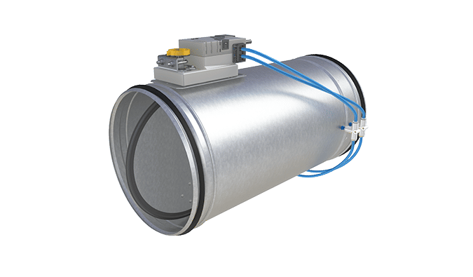
Halton Max MLC – Airflow management damper (VAV)
product
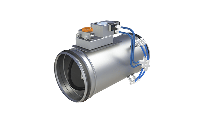
Halton Max MOC – Airflow management damper (VAV)
product
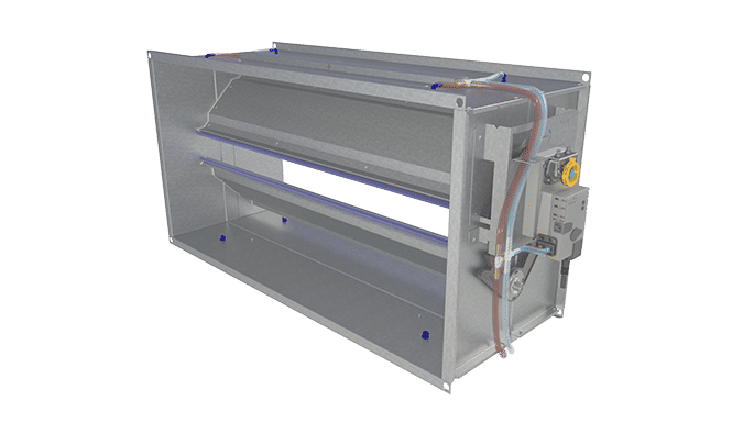
Halton Max MOS – Airflow management damper (VAV)
product
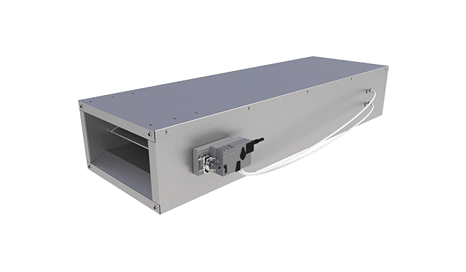
Halton Max MSB – Slim airflow management damper (VAV)
product
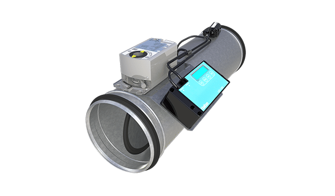
Halton Max MUC – Ultrasound airflow management damper (VAV)
product

Halton PRA – Airflow management damper (CAV)
product
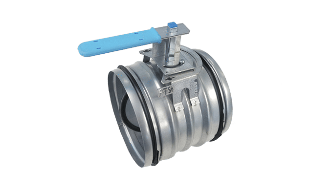
Halton PTS – Airflow management damper (single-blade)
product
Halton RDR – Adjustable airflow regulator
product
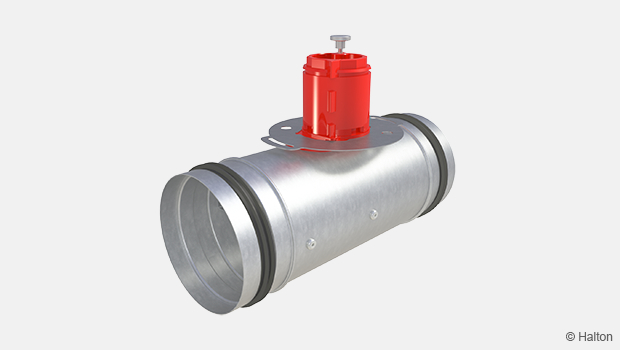
Halton RMC – Airflow management damper (CAV)
product

Halton RMK – Airflow management damper (CAV)
product
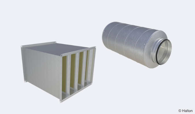
Halton SA – Sound attenuator
product
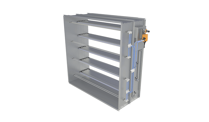
Halton UKV – Airflow management damper (VAV)
product
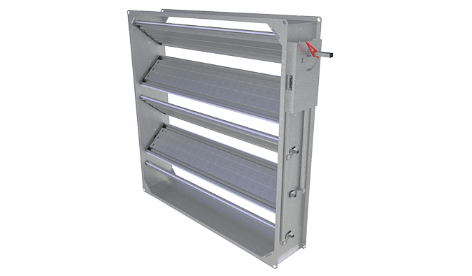
Halton UTK – Multi-blade airflow management damper (CAV)
product
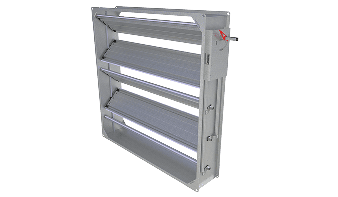
Halton UTT – Multi-blade airflow management damper (CAV)
product

Halton Vita VLR – Room airflow controller for Halton Vita Lab solutions
product