Product / RMC
Overview
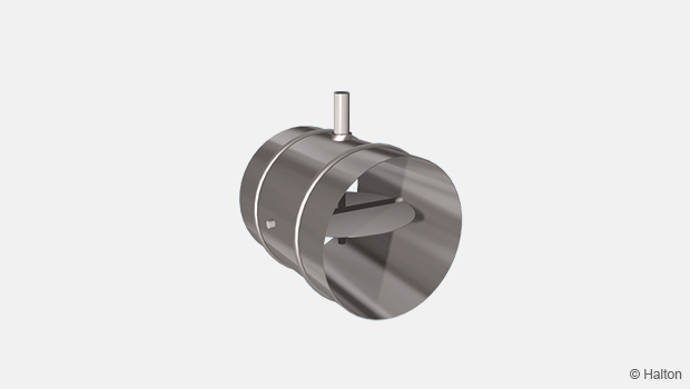
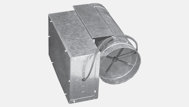
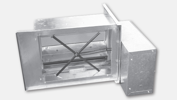
• Constant airflow damper without external power supply, self-balancing operation
• Effective commissioning
• Large operation area, pressure range of 50…600 Pa and optionally up to 1000 Pa
• Galvanised steel design
Product models
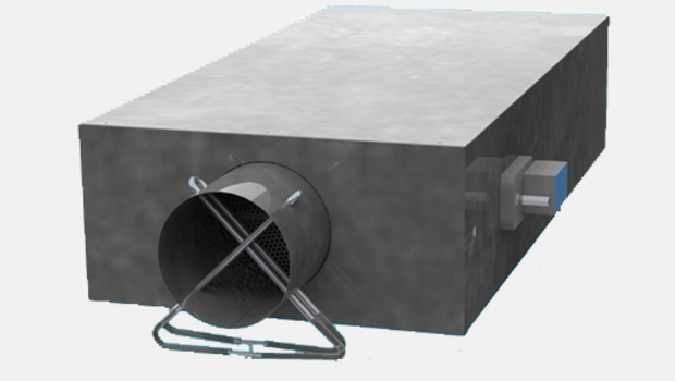
• Models with and without insulated casing
Dimensions
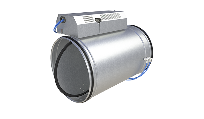
Halton RMC/N (without insulation)
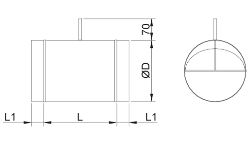
Halton RMC/I (insulated)
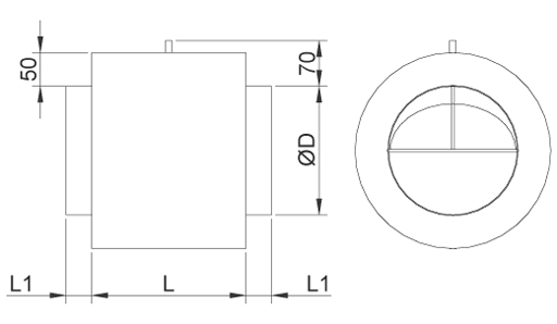
| NS [mm] |
L [mm] |
L1 [mm] |
ØD [mm] |
| 100 | 170 | 40 | 99 |
| 125 | 170 | 40 | 124 |
| 160 | 240 | 40 | 159 |
| 200 | 240 | 40 | 199 |
| 250 | 240 | 40 | 249 |
| 315 | 220 | 60 | 314 |
| 400 | 295 | 60 | 399 |
Material
| Part | Material |
| Housing | Galvanised steel |
| Damper blade | Aluminium |
| Damper blade bearings | PTFE |
| Tube for the adjustment | Plastic |
| Ring seals | Rubber |
Product models
| Product model | Code | Description |
| Standard | N | No insulation |
| External insulation | I | Mineral wool, thickness 50 mm, for sound insulation and reduction of heat transfer |
Function
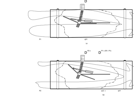
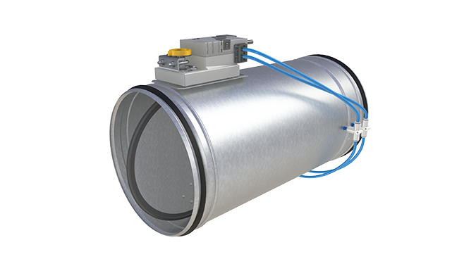
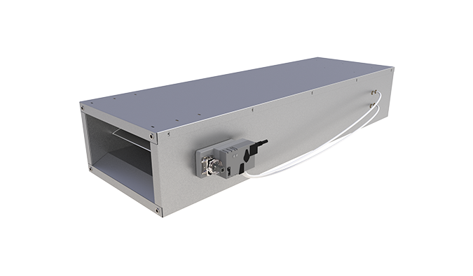
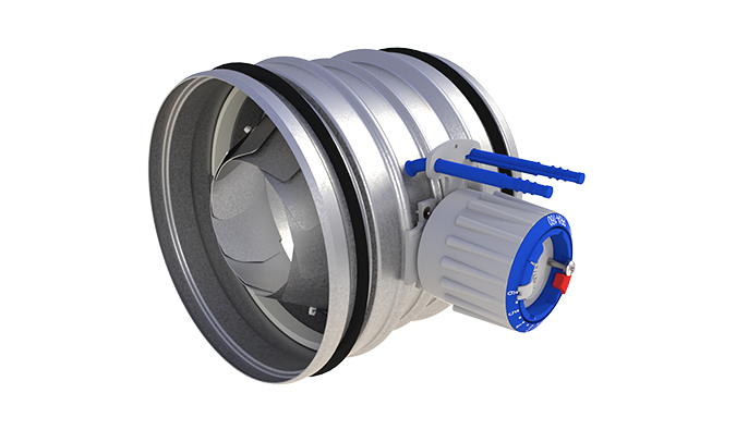
Constant airflow damper Halton RMC is an independent control element operating without an external power supply, maintaining the required airflow rate regardless of upstream pressure changes. Consequently, system balancing is not needed.
As the dynamic pressure in the duct branch increases, the damper turns, thus increasing the pressure loss and preventing an excessive increase in the airflow rate. Similarly, as the dynamic pressure decreases, the spring returns the blade to the open position, reducing the pressure loss and thus maintaining a constant airflow rate.
The constant airflow damper includes a damper blade, supported by bearings and connected to an adjustment spring. As a result of the balance between aerodynamic forces and the spring effect, the necessary throttling effect is achieved and the set airflow rate is achieved.
Operation range
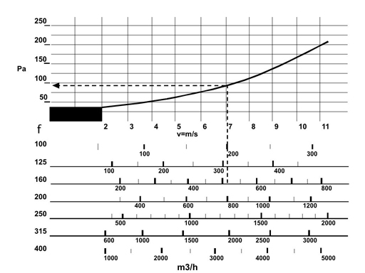
The constant airflow damper operates from a minimum pressure difference over the unit, which depends on the air velocity (see diagram below) to a maximum pressure difference of 1000 Pa.
For example, if air velocity in duct is 7 m/s, the unit pressure loss is approximately 100 Pa or above.
| Size | qv min. |
qv max |
qv min. |
qv max |
v min. |
v max |
dPst min.* |
dPs max |
| mm | m³/h | m³/h | l/s | l/s | m/s | m/s | Pa | Pa |
| 100 | 70 | 220 | 19 | 61 | 2.5 | 7.8 | 50 | 1000 |
| 125 | 100 | 280 | 28 | 78 | 2.3 | 6.3 | 50 | 1000 |
| 160 | 180 | 500 | 50 | 139 | 2.5 | 6.9 | 50 | 1000 |
| 200 | 250 | 900 | 69 | 250 | 2.2 | 8.0 | 50 | 1000 |
| 250 | 500 | 1500 | 139 | 417 | 2.8 | 8.5 | 50 | 1000 |
| 315 | 800 | 2200 | 222 | 611 | 2.8 | 7.8 | 50 | 1000 |
| 400 | 1000 | 3800 | 278 | 1250 | 2.2 | 8.4 | 50 | 1000 |
Control inaccuracy less than 20%.
Installation
Safety distances for the damper
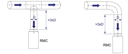
The airflow control damper should be installed in undisturbed airflow. The airflow velocity profile in the duct should be sufficiently even, without disturbances caused by bends, T-branches etc.
The necessary safety distance after a bend or a T-branch is 3 x the duct diameter.
The airflow control damper should be installed so that the arrow on the damper corresponds to the direction of the airflow. See the installation examples below.
Specification
The constant airflow damper operates without an electric or pneumatic external power supply.
The damper operates with an adjustable spring.
The damper with a manual adjustment device shall be able to be easily set or reset on the work site, during commissioning.
The damper casing is made of galvanised steel and the blade of aluminium.
The damper casing is insulated with mineral wool as sound and heat insulation material (optional).
Order Code
RMC/S-D; ZT
S = Model
N Standard
I Insulated (casing 50 mm)
D = Duct connection [mm]
100, 125, 160, 200, 250, 315, 400
Other options and accessories
ZT = Tailored product
N No
Y Yes (ETO)
Order code example
RMC/N-100, ZT=N
