Product / MDC
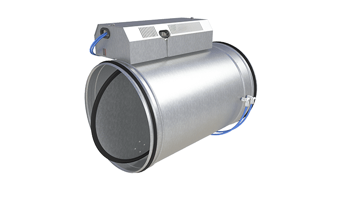
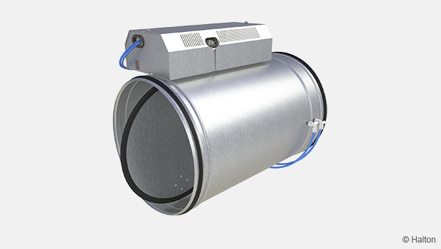
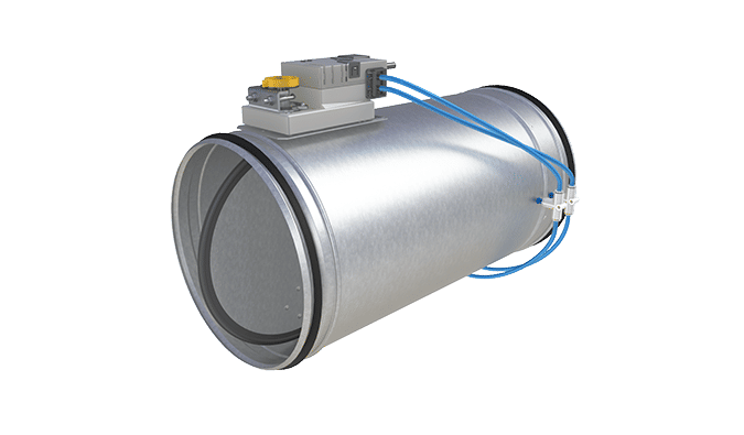
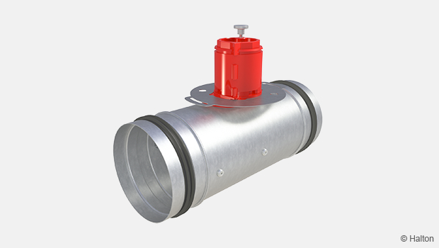
Halton Max MDC – Zone control damper for Halton Workplace system
Terminated as of 01.03.2026
-> replaced with Halton Max MLC
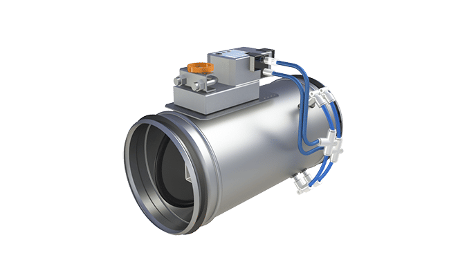
This airflow management damper operates as a fundamental element of the supply and exhaust ductwork zones in the Halton Workplace system.
- Airflow is measured with calibrated orifice plate
- Pressure-independent operation
Overview
Terminated as of 01.03.2026
-> replaced with Halton Max MLC
The Halton Max MDC airflow management damper operates as a fundamental element of the supply and exhaust ductwork zones in the Halton Workplace systems.
This management damper can operate either in duct static pressure control mode or duct airflow control mode.
Typically at the Halton Workplace zonal level, supply air is kept at constant pressure with the Halton Max MDC. Exhaust air is operated with the airflow control mode.
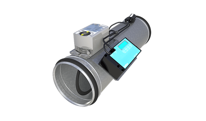
For ductwork static pressure control, airflow management damper is used with static pressure measurement unit Halton MSS.
Application
- Airflow is measured with calibrated orifice plate
- Airflow control damper for Halton Workplace zone control applications
- Circular pressure-independent variable airflow control damper
- Supply and exhaust installations
Key features
- Pressure-independent operation
- Duct static pressure control and airflow rate control modes are available
- For duct static pressure control used with the Halton MSS
- Insensitive to dust collection in ductwork
- Enables flexibility in terms of space layout
- Project specific settings are preset at the factory
- Controller settings are easily adjustable on site with BACnet/IP connection or web browser
- Can be connected to Buildings Management System (BMS)
- Velocity range 0,5 — 6 m/s
- General measurement uncertainty: Accuracy ±10 %
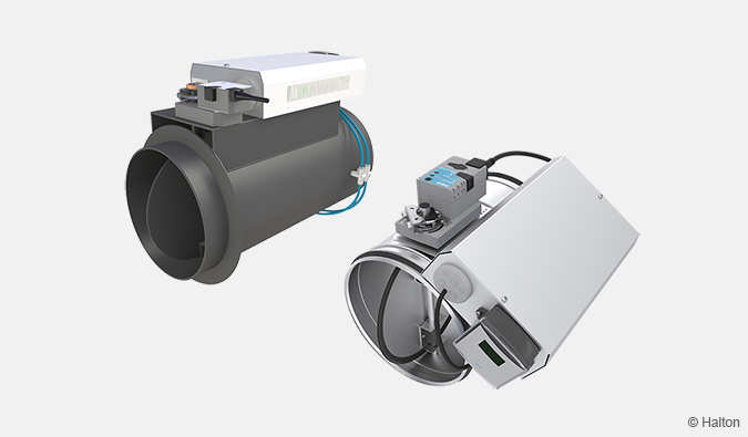
Operating principle
The damper can operate either as a supply or an exhaust unit. It maintains the required airflow level or pressure level through static pressure measurement. For ductwork static pressure control, static pressure measurement unit (Halton MSS) with pressure transmitter is used for zone ductwork static pressure measurement.
The damper contains airflow measurement with orifice plate, controller, pressure measurement sensor and an actuator for controlling the damper blade.
The airflow controller can receive the airflow control signal via
- BACnet/IP
Key technical data
| Feature | Value |
| Duct connection sizes | ø125-500 mm |
| Material | Galvanised steel |
| Air velocity range |
|
| Operating range (ambient temperature) | 0-50 ℃ |
| Ambient relative humidity (non-condensing) | < 95% |
| Communication interface | BACnet/IP |
Operating modes
|
|
| Accessories |
|
| Protection class |
|
| Power supply |
|
| Standards and certifications |
|
| Maintenance | Maintenance-free |
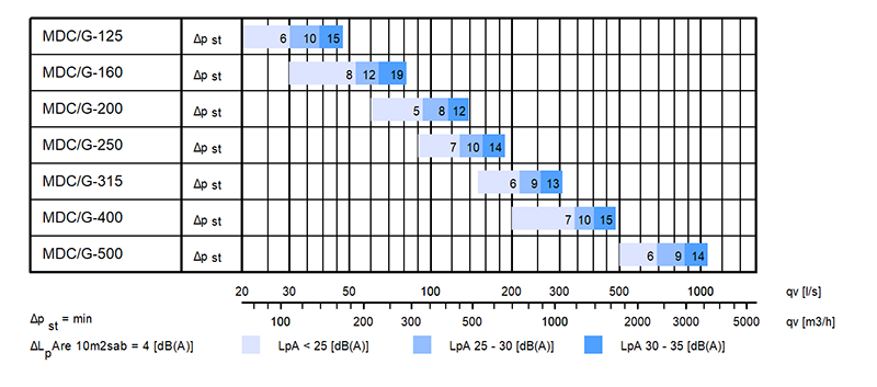
Quick selection
The operable airflow range for Halton Max MDC corresponds to duct air velocities 0.5-6 m/s.
The below example shows the airflow ranges and noise levels with damper blade fully open.
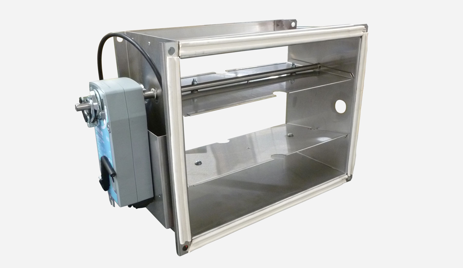
Structure and materials
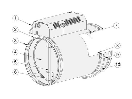
| No. | Part | Material |
| 1 | Control box | Galvanised steel |
| 2 | Duct seal gasket | Rubber |
| 3 | Casing | Galvanised steel |
| 4 | Blade | Galvanised steel |
| 5 | Shaft | Galvanised steel |
| 6 | Blade gaskets | EPDM rubber |
| 7 | Orifice plate gasket | EPDM rubber |
| 8 | Orifice plate | Galvanised steel |
| 9 | Tube connectors | Polyacetal |
| 10 | Measurement tabs | Polyurethane |
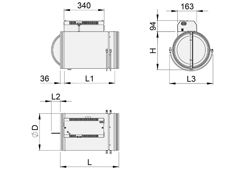
Dimensions and weight
Model without insulation
| NS [mm] |
⌀D [mm] |
L [mm] |
L1 [mm] |
L2 [mm] |
L3 [mm] |
H [mm] |
Weight [kg] |
| 125 | 124 | 329 | 257 | – | 184 | 134 | 5.5 |
| 160 | 159 | 329 | 257 | – | 219 | 169 | 5.8 |
| 200 | 199 | 494 | 422 | 15 | 259 | 209 | 6.5 |
| 250 | 249 | 494 | 422 | 38 | 309 | 259 | 7.2 |
| 315 | 314 | 494 | 422 | 70 | 374 | 324 | 8.0 |
| 400 | 399 | 620 | 545 | 115 | 459 | 409 | 9.9 |
| 500 | 499 | 620 | 545 | 95 | 559 | 509 | 17.7 |
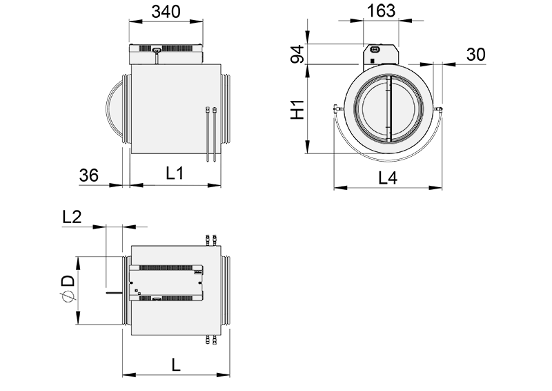
Model with insulation (50 mm)
| NS [mm] |
⌀D [mm] |
L [mm] |
L1 [mm] |
L2 [mm] |
L4 [mm] |
H [mm] |
Weight [kg] |
| 125 | 124 | 329 | 257 | – | 305 | 225 | 6.3 |
| 160 | 159 | 329 | 257 | – | 340 | 260 | 6.7 |
| 200 | 199 | 494 | 422 | 15 | 380 | 300 | 8.2 |
| 250 | 249 | 494 | 422 | 38 | 430 | 350 | 9.2 |
| 315 | 314 | 494 | 422 | 70 | 495 | 415 | 10.3 |
| 400 | 399 | 620 | 545 | 115 | 580 | 500 | 13.7 |
| 500 | 499 | 620 | 545 | 95 | 680 | 600 | 22.4 |
Specification
The pressure-independent variable airflow management damper is made of galvanised steel, with an airflow measurement with orifice plate.
Duct connection shall include integral airtight rubber gaskets.
The management damper section shall contain airflow measurement, flow controller and damper actuator.
The variable air volume control damper includes both constant pressure and airflow control applications, and, is available for BACnet/IP communication protocol.
Construction
- Damper includes airflow measurement with orifice plate, controller, pressure measurement sensor and damper actuator.
- Duct connection includes integral airtight rubber gaskets.
- Damper with blade gasket: the tightness of the control damper in closed position conforms to standard EN1751 class 4 and casing tightness to EN 1751 class C.
- Damper with optional external insulation include a 50 mm mineral wool insulation layer
- Closing blade with gasket ensure complete shut-off function
Material
- Galvanised steel
Electrical data
- Communication protocol BACnet/IP
- Power supply voltage 230 V AC
- Maximum load for transformer 20 VA
Parameter settings
- Project specific parameters are preset at the factory
- Controller settings are adjustable on site with BACnet/IP connection or web browser
Accessories
- Sound attenuator for noise reduction. An access panel can be added for easy maintenance.
Installation
Installation options
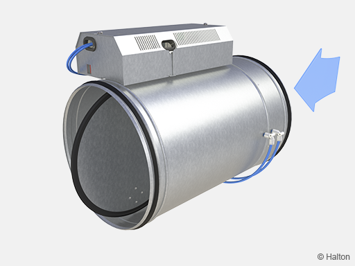
The Halton Max MDC airflow control damper is installed taking into account the required safety distances. Install the unit into ductwork in such a way that the airflow direction through the unit is as indicated with the arrow label in the unit casing.
Space requirements
Disturbances in the ductwork such as duct bends, T-branches and sound attenuators cause turbulence and an uneven airflow. This can lead to fluctuation and inaccuracy in measurement values.
To ensure the accuracy of the airflow measurement, the minimum safety distances are defined for different installation options below. The safety distance is same for all damper sizes.
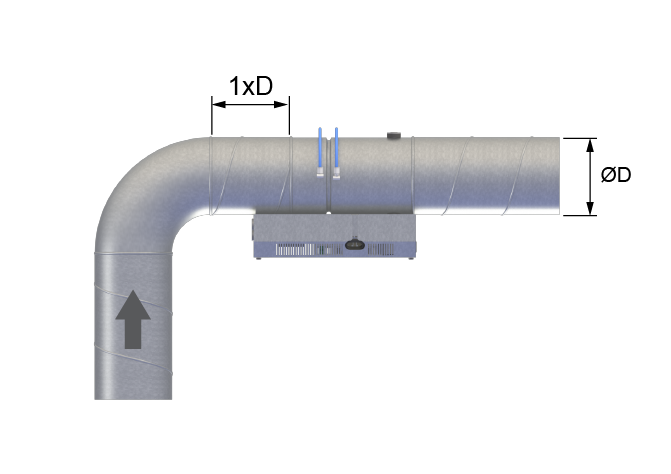
Fig. 1. After 90° elbow
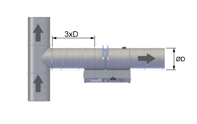
Fig. 2. T-branch side flow
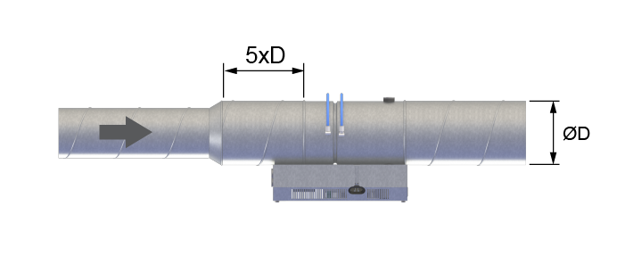
Fig. 3. After enlarger
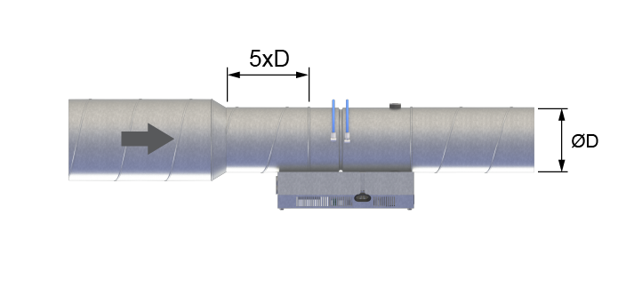
Fig. 4. After reducer
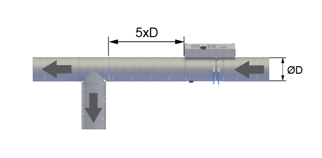
Fig. 5. Before T-branch
The recommended safety distance between Halton Max MDC control damper and Halton MSS measuring unit is min. 5xD.
Wiring
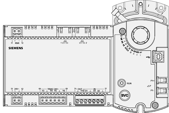
| Pin | Description | Terminal | Module | Channel |
| 1, 2 Ethernet | 2x RJ45 interface for 2-port ethernet switch | – | – | – |
| 11, 12 KNX | KNX connection | +, – | – | – |
| USB | USB interface | – | – | – |
| 51…52 power 24 V AC | Power supply SELV / PELV AC 24 V | V~ | – | – |
| System neutral | Ʇ | – | – | |
| 64…69 Triac outputs | Switching output AC 24V | Y3…Y6 | 11 | 3…6 |
| 71 Digital output | Positioning output DC 0…10 V | Y10 | 21 | 1, 2 |
| System neutral | Ʇ | – | – | |
| 73…77 | Digital input | D1 | 1 | 1 |
| Universal inputs | X1, X2 | 1 | 5, 6 | |
| System neutral | Ʇ | – | – | |
| ΔP Differential pressure detector | Connected to the higher pressure | P1+ | 31 | 1 |
| Connected to the lower pressure | P1- | 31 | 1 | |
| Motor Control Outputs | Shaft turns clockwise (CW) | – | 11 | 2 |
| Shaft turns counter clockwise (CCW) | – | 11 | 1 | |
| Service | Service button | SVC | – | – |
| Display | Operation LED | RUN | – | – |
Wiring examples

Fig.6. Halton Max MDC with static pressure control

Fig.7. Halton Max MDC with airflow control
Commissioning
Airflow control
Airflow rate ranges of the Halton Max MDC are presented in the table below. The airflow rate range is valid both for pressure and airflow control applications.
On typical Halton Workplace zone control application, the supply airflow is based on constant pressure control and exhaust airflow is based on airflow control. In this application the actual supply airflow is measured and sent as a setpoint to exhaust airflow controller. Therefore, airflow rate ranges are essential factors both for supply and exhaust air applications.
| NS | k factor [l/s] | k factor [m3/h] |
| 125 | 7.5 | 27.0 |
| 160 | 11.3 | 40.6 |
| 200 | 21.7 | 78.0 |
| 250 | 27.7 | 99.7 |
| 315 | 44.1 | 158.8 |
| 400 | 67.3 | 242.3 |
| 500 | 101.8 | 366.5 |
| NS | l/s min @ 0.5 m/s |
l/s max @ 6 m/s |
m3/h min @ 0.5 m/s |
m3/h max @ 6 m/s |
| 125 | 6,9 | 74.0 | 24.8 | 266.0 |
| 160 | 10.0 | 121.0 | 36.0 | 434.0 |
| 200 | 15.9 | 188.4 | 56.5 | 678.0 |
| 250 | 25.0 | 294.4 | 90.0 | 1060.0 |
| 315 | 40.0 | 467.0 | 144.0 | 1682.0 |
| 400 | 63.5 | 753.6 | 229.0 | 2713.0 |
| 500 | 99.5 | 1177.0 | 358.0 | 4237.0 |
The actual airflow rate can be calculated as a function of differential pressure at the Halton Max MDC measurement probe and the measurement probe k factor. The proper k factor can be found in an attachment for the product.
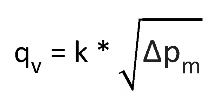
qv Actual airflow rate [l/s]
k k factor of the product
Δpm Differential pressure of measurement probe [Pa]
The Halton Max MDC airflow management damper is equipped with a pressure sensor, and there is a very low airflow through the differential pressure sensor of the controller. Therefore, a manual differential measurement manometer can be connected in parallel to the airflow controller (for example with tube T-branches) and both measurements can operate in parallel with continuous control.
Duct pressure control
Zone pressure setpoint is set as a network variable. The static pressure setpoint range on Halton Workplace application is 40 to 200 Pa.
The actual measured static pressure can be read from the LED display of the Halton MSS static pressure measurement unit with pressure transmitter. Pressure values can be read as network variables.
Product selection examples
Zone exhaust concepts
The room system options are operated by the zone VAV control damper (MDC) with constant pressure ductwork (pressure dependent) for supply air and constant velocity ductwork for exhaust air (pressure independent).
Centralised exhaust concept
Exhaust airflows are transferred through ceiling or wall grilles towards the common exhaust unit.

Individual room or zone exhaust concept
Exhaust airflows are transferred through ceiling or wall grilles directly to room branch ducts and via the main branch to the main riser duct.

Hybrid (mixed) exhaust concept
Some spaces are equipped with exhaust grilles or diffusers (usually meeting rooms and other separate spaces) and other spaces are transferring the air towards the common exhaust (usually open spaces and other common areas without walls)

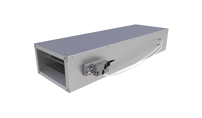
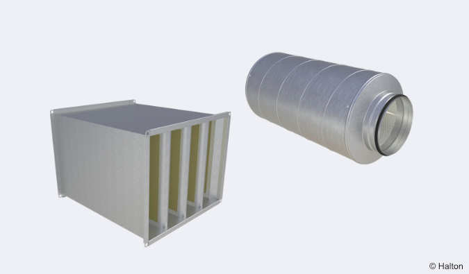
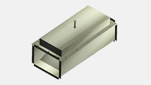
Sound attenuators
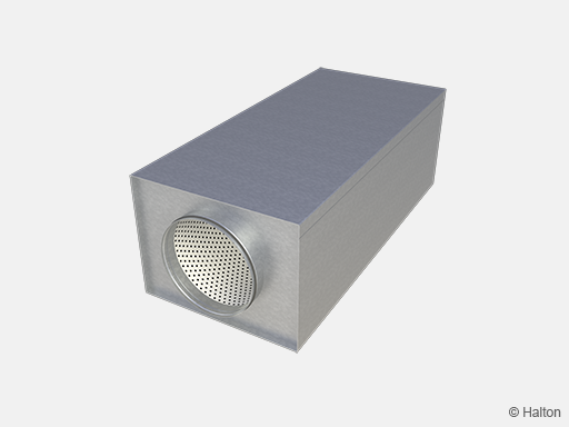
Description
Halton offers high-quality rectangular sound attenuators with round duct connection for reducing noise levels in the duct. The sound attenuators are available as accessory with the following options:
- Three lengths: 600, 1000 and 1250mm
- Connection types:
- D2=D1. The duct (D2) and damper (D1) connections are the same size.
- D2>D1. The duct connection (D2) is one size larger than the damper connection (D1).
- Insulation material options:
- Polyester fibre (PEF), tested according to ISO 7235, class C tightness level
- Mineral wool (MW), class C tightness level
- Available with or without access panel for maintenance purposes
Technical data
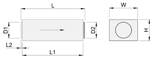
D1 is connected directly to the damper with female-type connection. D2 is attached to the duct with male-type connection. The above picture depicts supply air installations. In exhaust installations, the airflow direction is from D2 to D1. The damper is always connected to D1.
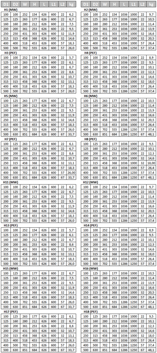
NOTE: Sizes 100 and 630 are not available for Halton Max MDC.
Examples of attenuation data
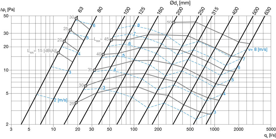
Fig. Attenuation data, L=600mm, material=PEF
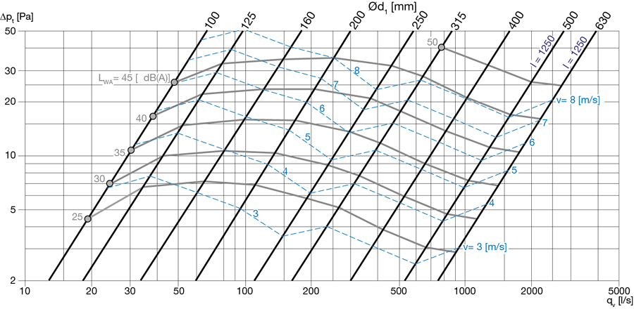
Fig. Attenuation data, L=1000mm, material=PEF
NOTE: For further information, contact Halton Sales.
Order code
MDC/S-D, MA-CU-CM-SA-ZT
S = Model
G Damper with blade gasket
I Damper with blade gasket, insulation 50 mm
D = Connection size [mm]
125, 160, 200, 250, 315, 400, 500
Other options and accessories
MA = Material
GS Galvanised steel
CU = Control unit
S1 DXR2.E10PL-102B (BACnet/IP), 10 Nm
CM = Control mode
F1 Supply airflow control
P1 Supply pressure control
F2 Exhaust airflow control
P2 Exhaust pressure control
SA = Sound attenuator (accessory)
NA Not assigned
H1 L 600 mm; Outlet = Inlet; Mineral wool
H2 L 1000/1250 mm; Outlet = Inlet; Mineral wool
H3 L 600 mm; Outlet = Inlet; Polyester fibre
H4 L 1000/1250 mm; Outlet = Inlet; Polyester fibre
H5 L 600 mm; Outlet > Inlet; Mineral wool
H6 L 1000/1250 mm; Outlet > Inlet; Mineral wool
H7 L 600 mm; Outlet > Inlet; Polyester fibre
H8 L 1000/1250 mm; Outlet > Inlet; Polyester fibre
H11 L 600 mm; Outlet = Inlet; Mineral wool; Access panel
H12 L 1000/1250 mm; Outlet = Inlet; Mineral wool; Access panel
H13 L 600 mm; Outlet = Inlet; Polyester fibre; Access panel
H14 L 1000/1250 mm; Outlet = Inlet; Polyester fibre; Access panel
H15 L 600 mm; Outlet > Inlet; Mineral wool; Access panel
H16 L 1000/1250 mm; Outlet > Inlet; Mineral wool; Access panel
H17 L 600 mm; Outlet > Inlet; Polyester fibre; Access panel
H18 L 1000/1250 mm; Outlet > Inlet; Polyester fibre; Access panel
ZT = Tailored product
N No
Y Yes (ETO)
Order code example
MDC/G-160, MA=GS, CU=S1, CM=F1, ZT=N
Downloads
"*" indicates required fields
ABD – Automated Balancing Damper for kitchen ventilation (CE)
product
ABD – Automatic balancing damper for kitchen ventilation (ETL)
product
CID-01 – Zero leakage isolation damper
product
Halton BOX – Airflow management unit (VAV)
product
Halton Max MDC – Zone control damper for Halton Workplace system
product
Halton Max MLC – Airflow management damper (VAV)
product
Halton Max MOC – Airflow management damper (VAV)
product
Halton Max MOS – Airflow management damper (VAV)
product
Halton Max MSB – Slim airflow management damper (VAV)
product
Halton Max MUC – Ultrasound airflow management damper (VAV)
product

Halton PRA – Airflow management damper (CAV)
product
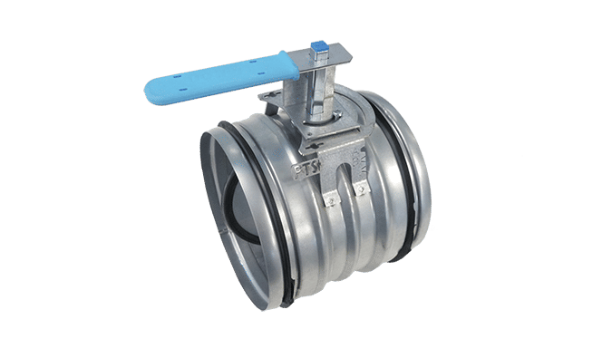
Halton PTS – Airflow management damper (single-blade)
product
Halton RMC – Airflow management damper (CAV)
product
Halton SA – Sound attenuator
product
Halton UKV – Airflow management damper (VAV)
product
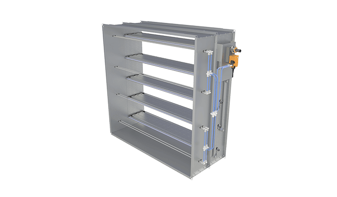
Halton UTK – Multi-blade airflow management damper (CAV)
product
Halton UTT – Multi-blade airflow management damper (CAV)
product

Halton Vita VLR – Room airflow controller for Halton Vita Lab solutions
product
Halton Vita VLS – Fume cupboard controller for Halton Vita Lab solutions
product
KBD – Exhaust hood balancing damper (ETL)
product