Product / MLC
Halton Max MLC – Airflow management damper (VAV)
The Halton Max MLC airflow management damper allows installation in narrow spaces without requiring safety distances in any case.!
It can operate either in duct static pressure control mode or duct airflow control mode depending on chosen control unit. The airflow management damper is designed to function also at very low air velocity and pressure.
The Halton Max MLC airflow management damper is particularly suitable for demand-based office applications.
- Air velocity range 0,5 — 6 m/s
- Shut-off operation tightness fulfils EN 1751 class 4
- Pressure-independent operation
Overview
The Halton Max MLC airflow management damper can be installed without safety distances in all installation cases. It can operate either in duct static pressure control mode or duct airflow control mode depending on chosen control unit. The airflow management damper is designed to function also at very low air velocity and pressure.
Applications
- For demanding and flexible office space requirements as minimal need of safety distance
- Supply and exhaust installations
Key features
- Air velocity range 0,5 — 6 m/s
- Airflow is measured with calibrated orifice plate
- Pressure-independent operation
- Duct static pressure control and airflow rate control modes are available
- For duct static pressure control used with the Halton MSS
- Insensitive to dust collection in ductwork
- Project specific settings are preset at the factory
- Wide range of control units available (analog, Modbus, BACnet/IP, LON,…).
- Can be connected to Buildings Management System (BMS)
Standards
- Casing tightness EN 1751 class C
- Shut-off operation tightness fulfils EN 1751 class 4
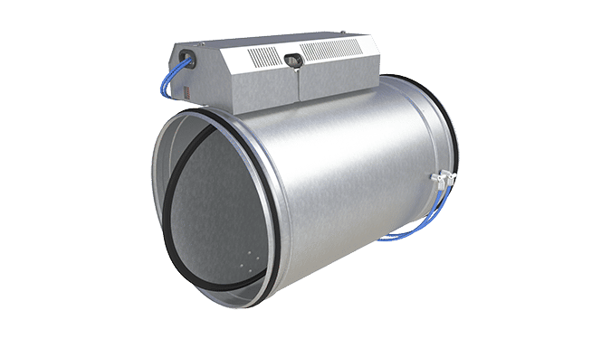
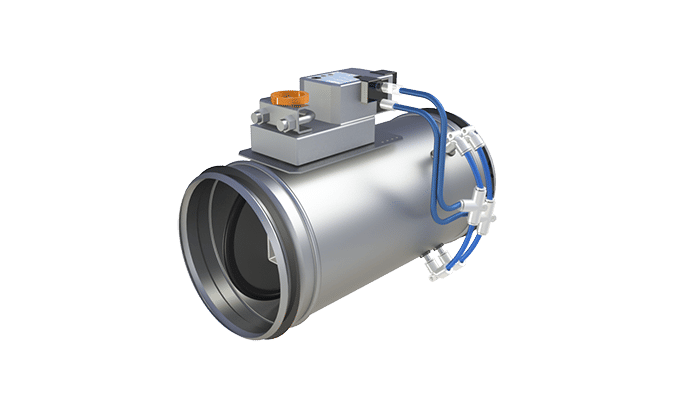
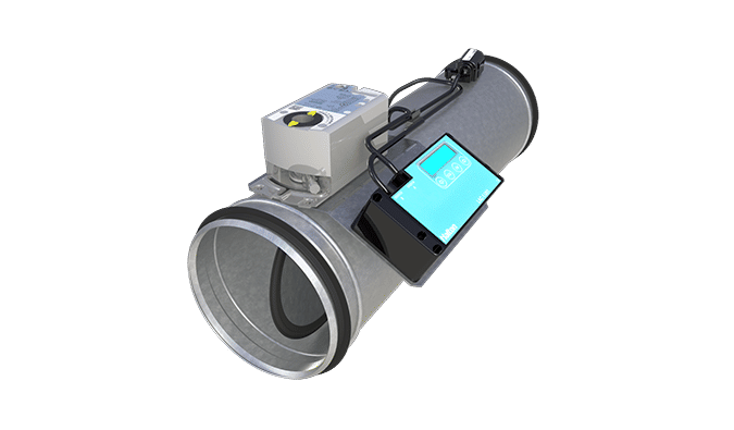
Operating principle
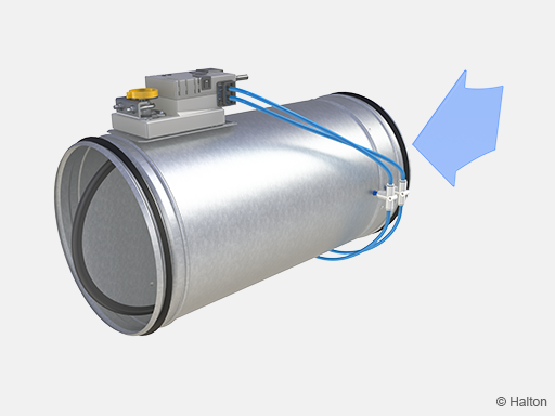
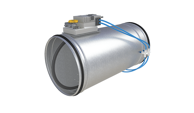
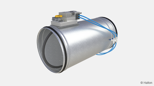
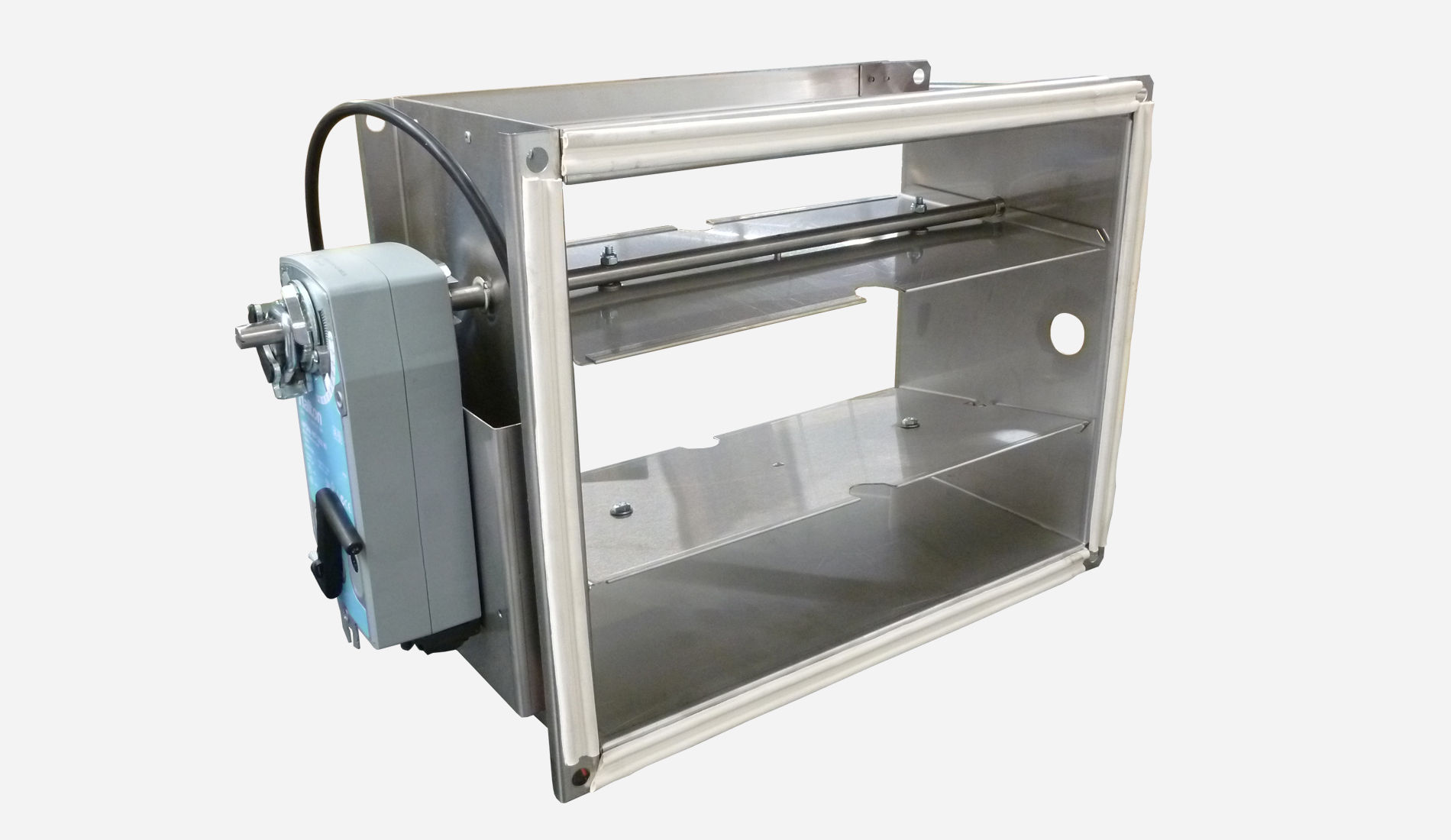
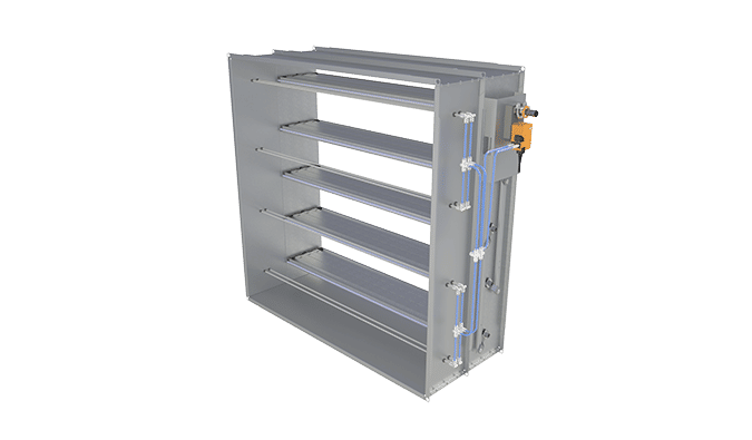
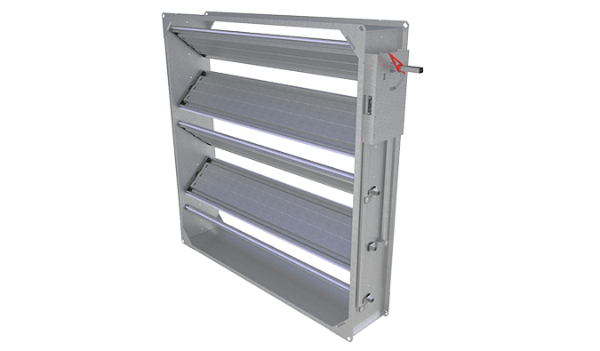
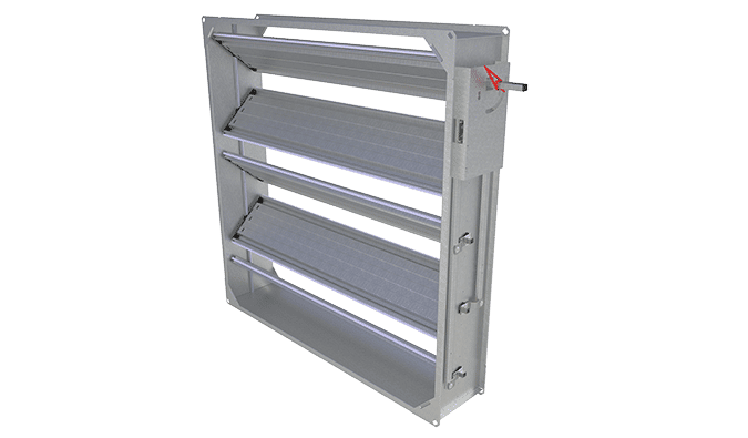
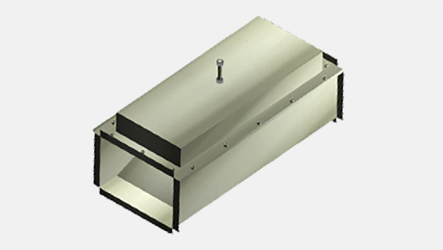
Fig.1. Halton Max MLC, airflow direction
The damper contains airflow measurement with orifice plate, a VAV airflow controller, an actuator and a blade with gasket. Depending on the actuator model, the VAV controller is a separate unit or integrated into the actuator.
The damper can operate either as a supply or an exhaust unit. It maintains the required airflow level or pressure level through static pressure measurement. For ductwork static pressure control, static pressure measurement unit (MSS) with pressure transmitter is used for zone ductwork static pressure measurement.
Changes in room conditions can be adjusted manually from an end-user interface or by different sensors such as occupancy or room pressure sensors, thermostats or timers. The conditions can also be managed remotely from a building management system (BMS). The control signal and the airflow measurement data from the pickup tubes are processed in the VAV controller. The VAV controller gives the actuator a command to change the position of the damper blade, in order to keep the airflow at the predefined setpoint.
The airflow setpoint can be modified between minimum and maximum settings from the room controller interface or a BMS. The VAV controller can also send actual value data back to the room interface controller. The communication protocol used for the signal between the room control interface and the VAV controller depends on the actuator model.
For more information about the available actuator models, see section Control units.
Key technical data
| Feature | Value |
| Duct connection sizes | ø125-500 mm |
| Material | Galvanised steel |
| Air velocity range |
|
| Operating range (ambient temperature) | 0-50 ℃ |
| Ambient relative humidity (non-condensing) | < 95% |
Operating modes
|
|
| Accessories |
|
| Standards and certifications |
|
Quick selection
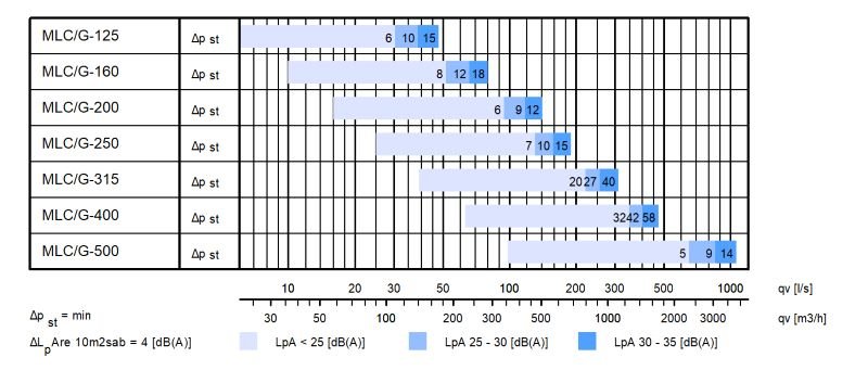
The operable airflow range for Halton Max MLC corresponds to duct air velocities 0.5-6 m/s.
The below example shows the airflow ranges and noise levels with damper blade fully open.
Structure and materials

| No. | Part | Material |
| 1 | Blade gasket | EPDM rubber |
| 2 | Shaft | Galvanised steel |
| 3 | Blade | Galvanised steel |
| 4 | Duct seal gasket | Rubber |
| 5 | Control unit | Plastic, steel, PVC cable |
| 6 | Casing | Galvanised steel |
| 7 | Orifice plate gasket | EPDM rubber |
| 8 | Orifice plate | Galvanised steel |
| 9 | Tube connectors | Polyacetal |
| 10 | Measurement tabs | Polyurethane |
Control units
A range of control units are available for various application needs.
All control units include an integrated dynamic differential pressure sensor with a low bypass airflow rate through the sensor element. Therefore not to be used in highly contaminated environments. Airflow rate limits are set at the factory.
| Controller | Notes | Torque Nm |
Damper size |
Communication interface |
Order code (link to datasheet) |
| Halton EM |
Analogue controller Manufacturer: Belimo |
5 | 125-250 | DC0..10V/ 2..10V |
EM = LMV-D3-MF-F.1 HI (DC 0/2…10 V), 5 Nm |
| Halton EK |
Analogue controller Manufacturer: Belimo |
10 | 125-500 | DC0..10V/ 2..10V |
EK = NMV-D3-MF-F.1 HI (DC 0/2…10 V), 10 Nm |
| Halton EC |
Controller with NFC connectivity for mobile onsite parameter adjustment (Belimo Assistant App). Analogue or MPbus. Manufacturer: Belimo |
5 | 125-250 | Belimo MP bus or 0..10V/2..10V |
EC = LMV-D3-MP (MP bus), 5 Nm |
| Halton EE |
Controller with NFC connectivity for mobile onsite parameter adjustment (Belimo Assistant App). Analogue or MPbus. Manufacturer: Belimo |
10 | 125-500 | Belimo MP bus or 0..10V/2..10V |
EE = NMV-D3-MP (MP bus), 10 Nm |
| Halton ER |
Controller with KNX Manufacturer: Belimo |
5 | 125-250 | KNX | ER = LMV-D3-KNX (KNX bus), 5 Nm |
| Halton ES |
Controller with KNX Manufacturer: Belimo |
10 | 125-500 | KNX | ES = NMV-D3-KNX (KNX bus), 10 Nm |
| Halton ET |
Controller with Modbus Manufacturer: Belimo |
5 | 125-250 | Modbus | ET = LMV-D3-MOD (Modbus RTU), 5 Nm |
| Halton EU |
Controller with Modbus Manufacturer: Belimo |
10 | 125-500 | Modbus | EU = NMV-D3-MOD (Modbus RTU), 10 Nm |
| Halton EH |
Analogue controller Manufacturer: Siemens |
5 | 125-250 | DC0..10V/ 2..10V |
EH = GDB181.1E/3 (DC 0/2…10 V), 5 Nm |
| Halton EG |
Analogue controller Manufacturer: Siemens |
10 | 125-500 | DC0..10V/ 2..10V |
EG = GLB181.1E/3 (DC 0/2…10V), 10 Nm |
| Halton EV |
Controller with KNX Manufacturer: Siemens |
5 | 125-250 | KNX communication |
EV = GDB181.1E/KN (KNX bus), 5 Nm |
| Halton T9 |
Controller with Modbus Manufacturer: Halton |
5 | 125-250 | DC0-10V and Modbus | T9 = NSVA-MOD-5H (DC 0-10 V and Modbus RTU), 5 Nm |
| Halton T11 |
Controller with Modbus Manufacturer: Halton |
10 | 125-500 | DC0-10V and Modbus | T11 = NSVA-MOD-10H (DC 0-10 V and Modbus RTU), 10 Nm |
| Halton V1 |
Analogue controller Manufacturer: Belimo |
5 | 125-250 | DC0..10V/ 2..10V |
V1 = LM24A-VST, (DC 0/2…10 V), 5 Nm + VRU-D3-BAC |
| Halton V2 |
Analogue controller Manufacturer: Belimo |
10 | 125-500 | DC0..10V/ 2..10V |
V2 = NMQ24A-VST, (DC 0/2…10 V), 10 Nm + VRU-D3-BAC |
| Halton V3 |
Analogue controller Manufacturer: Belimo |
4 | 125-250 | DC0..10V/ 2..10V |
V3 = LMQ24A-VST, 2.5 sec (DC 0/2…10 V), 4 Nm + VRU-D3-BAC |
| Halton V4 |
Analogue controller Manufacturer: Belimo |
8 | 125-500 | DC0..10V/ 2..10V |
V4 = NMQ24A-VST, 4 sec (DC 0/2…10 V), 8 Nm + VRU-D3-BAC |
| Halton EW |
Actuator with KNX Manufacturer: Siemens |
10 | 125-500 | KNX communication |
EW = GLB181.1E/KN (KNX bus), 10 Nm |
| Halton EB |
Actuator with Modbus RTU (RS-485) Manufacturer: Siemens |
5 | 125-250 | Modbus communication | EB = GDB181.1E/MO (Modbus RTU), 5 Nm |
| Halton EF |
Actuator with Modbus RTU (RS-485) Manufacturer: Siemens |
10 | 125-500 | Modbus communication | EF = GLB181.1E/MO (Modbus RTU), 10 Nm |
| Halton HM |
Controller include actuator with LonWorks Manufacturer: Distech |
5 | 125-250 | LonWorks communication | HM = ECL-VAV-S, HAV (LonWorks), 5Nm |
| Halton HK |
Modulating actuator from Belimo: Controller LonWorks Manufacturer: Distech |
10 | 125-500 | LonWorks communication | HK = ECL-VAV-N, HAV + NM24A-SR (LonWorks), 10 Nm |
Dimensions and weight
Model without insulation

| NS [mm] |
⌀D [mm] |
L [mm] |
L1 [mm] |
L2 [mm] |
L3 [mm] |
H [mm] |
Weight [kg] |
| 125 | 124 | 329 | 257 | – | 184 | 134 | 2.3 |
| 160 | 159 | 329 | 257 | – | 219 | 169 | 2.6 |
| 200 | 199 | 494 | 422 | 15 | 259 | 209 | 3.3 |
| 250 | 249 | 494 | 422 | 38 | 309 | 259 | 3.9 |
| 315 | 314 | 494 | 422 | 70 | 374 | 324 | – |
| 400 | 399 | 620 | 545 | 115 | 459 | 409 | – |
| 500 | 499 | 620 | 545 | 95 | 559 | 509 | – |
Model with insulation [50 mm]

| NS [mm] |
⌀D [mm] |
L [mm] |
L1 [mm] |
L2 [mm] |
L4 [mm] |
H [mm] |
Weight [kg] |
| 125 | 124 | 329 | 257 | – | 305 | 225 | 2.7 |
| 160 | 159 | 329 | 257 | – | 340 | 260 | 3.6 |
| 200 | 199 | 494 | 422 | 15 | 380 | 300 | 4.4 |
| 250 | 249 | 494 | 422 | 38 | 430 | 350 | 5.3 |
| 315 | 314 | 494 | 422 | 70 | 495 | 415 | – |
| 400 | 399 | 620 | 545 | 115 | 580 | 500 | – |
| 500 | 499 | 620 | 545 | 95 | 680 | 600 | – |
Specification
The pressure-independent variable airflow management damper is made of galvanised steel, airflow measurement with orifice plate. Duct connection shall include integral airtight rubber gaskets. The management damper shall contain airflow measurement, flow controller and damper actuator. It can operate either in duct static pressure control mode or duct airflow control mode. The airflow management damper can be installed without safety distances.
Construction
- Damper includes airflow measurement with orifice plate and damper control unit.
- Duct connection includes integral airtight rubber gaskets.
- Damper with blade gasket: the tightness of the control damper in closed position conforms to standard EN1751 class 4 and casing tightness to EN 1751 class C.
- Damper with optional external insulation include a 50 mm mineral wool insulation layer
- Closing blade with gasket ensure complete shut-off function
Material
- Galvanised steel
Parameter settings
- Project specific parameters are preset at the factory according to customer specific requirements.
Installation
Installation options
The Halton Max MLC airflow control damper can be installed without safety distances. Accuracy of the measured airflow is given in a table below. Install the unit into ductwork in such a way that the airflow direction through the unit is as indicated with the arrow label in the unit casing.
Space requirements
Disturbances in the ductwork such as duct bends, T-branches and sound attenuators cause turbulence and an uneven airflow. This can lead to fluctuation and inaccuracy in measurement values.
The space between airflow damper and above mentioned disturbance can be set to 0D. Picture below demonstrates what 0xD means (see Fig. 2.). The accuracy varies according airflow and unit size (see chapter below: Accuracy of measurement with different airflows)
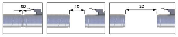
Fig.2. Safety distance examples
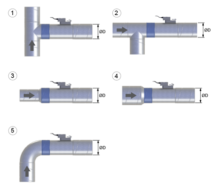
Fig.3. Installation cases
| Nr. | Installation cases | Safety distance |
| 1. | T-branch, side duct | 0D |
| 2. | T-branch, main duct | 0D |
| 3. | Reducer, < D | 0D |
| 4. | Reducer, > D | 0D |
| 5. | Bend, elbow 90° | 0D |
Table 1. Safety distances of Halton Max MLC
Accuracy of measurement with different airflows
| Size | Airflow [l/s] | Airflow [m3/h] | Accuracy of measurement with 0D [%] |
| 125 | 7 | 24.8 | 15 |
| 28 | 100 | 10 | |
| 53 | 190 | 8 | |
| 74 | 266 | 5 | |
| 160 | 10 | 36 | 15 |
| 40 | 145 | 10 | |
| 81 | 290 | 8 | |
| 121 | 434 | 5 | |
| 200 | 16 | 56.5 | 15 |
| 63 | 226 | 10 | |
| 126 | 452 | 8 | |
| 188 | 678 | 5 | |
| 250 | 25 | 90 | 15 |
| 98 | 354 | 10 | |
| 197 | 710 | 8 | |
| 294 | 1060 | 5 | |
| 315 | 39 | 140 | 15 |
| 153 | 562 | 10 | |
| 312 | 1123 | 8 | |
| 468 | 1685 | 5 | |
| 400 | 63 | 227 | 15 |
| 251 | 904 | 10 | |
| 503 | 1811 | 8 | |
| 754 | 2714 | 5 | |
| 500 | 98 | 353 | 15 |
| 393 | 1415 | 10 | |
| 785 | 2826 | 8 | |
| 1178 | 4241 | 5 |
Pressure control
In pressure control operation, the recommended safety distance between Halton Max MLC airflow damper and Halton MSS measuring unit is min. 5D (Fig.4.)
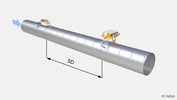
Fig.4. Halton Max MLC and Halton MSS, safety distance min. 5D
Wiring
The wiring must be carried out by professional technicians in accordance with local regulations. For the power supply, a safety-isolating transformer must be used.
The responsibilities between Halton and 3rd party are specified in the following example wiring diagram for a typical variable airflow control application:
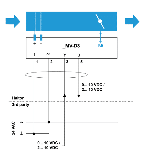
| No. | Key | Description |
| 1 | ⟂ | 24 VAC system neutral |
| 2 | ~ | 24 VAC live |
| 3 | Y | 2…10- or 0…10-VDC airflow setpoint signal input |
| 5 | U5 | 2…10- or 0…10-VDC airflow feedback signal output |
The following picture shows a typical variable airflow control application without cables.
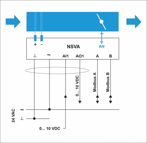
| Wire colour | Key | Description |
| Black | ⟂ | 24 VAC system neutral |
| Red | ~ | 24 VAC live |
| Gray | AI1 | Analog input |
| Purple | AO1 | Output for airflow feedback signal |
| Yellow | A | Data receive/send line A |
| Green | B | Data receive/send line B |
Commissioning
Airflow control
Airflow rate ranges of the Halton Max MLC are presented in the table below. The airflow rate range is valid both for pressure and airflow control applications.
| NS [mm] |
l/s min @ 0.5 m/s |
l/s max @ 6 m/s |
m3/h min @ 0.5 m/s |
m3/h max @ 6 m/s |
| 125 | 6,9 | 74.0 | 24.8 | 266.0 |
| 160 | 10.0 | 121.0 | 36.0 | 434.0 |
| 200 | 15.9 | 188.4 | 56.5 | 678.0 |
| 250 | 25.0 | 294.4 | 90.0 | 1060.0 |
| 315 | 39.0 | 468.0 | 140.0 | 1683.0 |
| 400 | 63.0 | 754.0 | 226.0 | 2714.0 |
| 500 | 98.0 | 1178.0 | 353.0 | 4241.0 |
The actual airflow rate can be calculated as a function of differential pressure at the Halton Max MLC measurement probe and the measurement probe k factor. The proper k factor can be found in an attachment for the product.
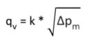
| qv | Actual airflow rate [l/s] or [m3/h] |
| Δpm | Differential pressure of measurement probe [Pa] |
| k | k-factor (see table below) |
| NS [mm] | k factor [l/s] | k factor [m3/h] |
| 125 | 7.5 | 27.0 |
| 160 | 11.3 | 40.7 |
| 200 | 21.7 | 78.1 |
| 250 | 27.7 | 99.7 |
| 315 | 44.1 | 158.8 |
| 400 | 67.3 | 242.3 |
| 500 | 101.8 | 366.5 |
Duct pressure control
The actual measured static pressure can be read from the LED display of the Halton MSS static pressure measurement unit with pressure transmitter. Pressure values can be read as network variables.
Accessories
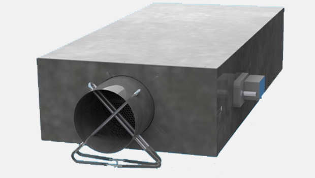
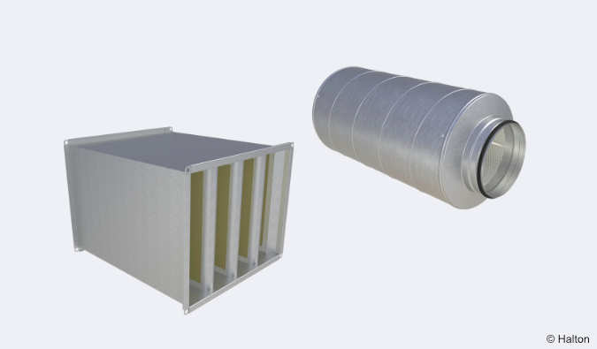
Sound attenuator (SA)

Halton SA’s rectangular and circular sound attenuators are constructed from high-quality materials They are made from galvanized steel and incorporate sound-absorbing materials such as mineral wool and polyester fibre, enhancing their noise absorption capacity. These sound attenuators are available as an accessory.
More information: Link to technical description
Duct sensor (DS1 = CO2G, Duct CO2)
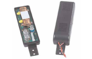
The transmitter designed to be installed in HVAC return air ducts. The size of the board and the dimensions of the case have been optimized to place the transmitter in small, i.e. 160 mm diameter, return air ducts. This product offers a sleek design, a simple analog output, and it is easy to install. The transmitter includes mounting hardware and installation instructions.
More information: Link to manufacture’s datasheet
Differential pressure transmitter (P1 = HDP-PE)
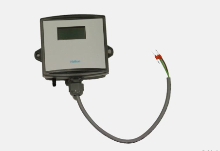
The Halton HDP-PE differential pressure sensor is a pressure-measuring device, used to measure differential pressures in the duct. It gives an accurate measurement of the airflow. The influence of process disturbances can be filtered by increasing the time constant.
More information: Link to manufacture’s datasheet
Transformer (TF1 = 230/24 transformer (35VA)
![]()
Transmitter 35 VA for DIN rail installation.
More information: Link to manufacture’s datasheet
Order code
MLC-S-D; MA-CU-SE-TF-ZT
| Main options | |
| S = Model | |
| G | Damper with blade gasket |
| I | Damper with blade gasket, insulation 50 mm |
| D = Duct connection size [mm] | 125, 160, 200, 250, 315, 400, 500 |
| Other options and accessories | |
| MA = Material | |
| GS | Galvanised steel |
| CU = Control unit | |
| EM | LMV-D3-MF-F.1 HI (DC 0/2…10 V), 5 Nm |
| EK | NMV-D3-MF-F.1 HI (DC 0/2…10 V), 10 Nm |
| EC | LMV-D3-MP (MP bus), 5 Nm |
| EE | NMV-D3-MP (MP bus), 10 Nm |
| ER | LMV-D3-KNX (KNX bus), 5 Nm |
| ES | NMV-D3-KNX (KNX bus), 10 Nm |
| ET | LMV-D3-MOD (Modbus RTU), 5 Nm |
| EU | NMV-D3-MOD (Modbus RTU), 10 Nm |
| EH | GDB181.1E/3 (DC 0/2…10 V), 5 Nm |
| EG | GLB181.1E/3 (DC 0/2…10V), 10 Nm |
| EV | GDB181.1E/KN (KNX bus), 5 Nm |
| EW | GLB181.1E/KN (KNX bus), 10 Nm |
| EB | GDB181.1E/MO (Modbus RTU), 5 Nm |
| EF | GLB181.1E/MO (Modbus RTU), 10 Nm |
| EF | GLB181.1E/MO (Modbus RTU), 10 Nm |
| T9 | NSVA-MOD-5H (DC 0-10 V and Modbus RTU), 5 Nm |
| T11 | NSVA-MOD-10H (DC 0-10 V and Modbus RTU), 10 Nm |
| V1 | LM24A-VST, (DC 0/2…10 V), 5 Nm+VRU-D3-BAC |
| V2 | NM24A-VST, (DC 0/2…10 V), 10Nm+VRU-D3-BAC |
| V3 | LMQ24A-VST, 2.5 sec (DC 0/2…10 V), 4 Nm+VRU-D3-BAC |
| V4 | NMQ24A-VST, 4 sec (DC 0/2…10 V), 8 Nm+VRU-D3-BAC |
| HM | ECL-VAV-S, HAV (LonWorks), 5Nm |
| HK | ECL-VAV-N, HAV + NM24A-SR (LonWorks), 10 Nm |
| SE = Sensors | |
| NA | Not assigned |
| DS1 | Duct sensor (CO2G, Duct CO2) |
| P1 | Differential pressure transmitter (HDP-PE) |
| TF = Transformer | |
| NA | Not assigned |
| TF1 | 230/24 transformer (35VA) |
| ZT = Tailored product | |
| N | No |
| Y | Yes (ETO) |
| Sub products and accessories (ordered separately) | |
| SA | Sound attenuator |
Order code example
MLC-G-160; MA=GS, CU=ER, SE=P1, TF=NA, ZT=N
Downloads
-
Halton Max MLC – Airflow management damper (VAV)
Data
en
-
Halton Max MLC – Ilmavirtasäädin (VAV)
Data
fi
-
Halton Max MLC – Régulateur à débit d’air variable (VAV)
Data
fr
-
Halton Max MLC – Variabelflödesspjäll
Data
se
-
Halton Max MLC flyer
Data
English (en) -
Halton Max MLC – Fiche technique
Data
Français (fr) -
Halton SA, sound attenuator – Technical description
Data
English (en) -
Halton Max MLC – Technical description
Data
English (en)
"*" indicates required fields
ABD – Automated Balancing Damper for kitchen ventilation (CE)
product
ABD – Automatic balancing damper for kitchen ventilation (ETL)
product
CID-01 – Zero leakage isolation damper
product
Halton BOX – Airflow management unit (VAV)
product
Halton Max MDC – Zone control damper for Halton Workplace system
product
Halton Max MLC – Airflow management damper (VAV)
product
Halton Max MOC – Airflow management damper (VAV)
product
Halton Max MOS – Airflow management damper (VAV)
product
Halton Max MSB – Slim airflow management damper (VAV)
product
Halton Max MUC – Ultrasound airflow management damper (VAV)
product

Halton PRA – Airflow management damper (CAV)
product
Halton PTS – Airflow management damper (single-blade)
product
Halton RMC – Airflow management damper (CAV)
product
Halton SA – Sound attenuator
product
Halton UKV – Airflow management damper (VAV)
product
Halton UTK – Multi-blade airflow management damper (CAV)
product
Halton UTT – Multi-blade airflow management damper (CAV)
product

Halton Vita VLR – Room airflow controller for Halton Vita Lab solutions
product
Halton Vita VLS – Fume cupboard controller for Halton Vita Lab solutions
product
KBD – Exhaust hood balancing damper (ETL)
product