Product / MSB
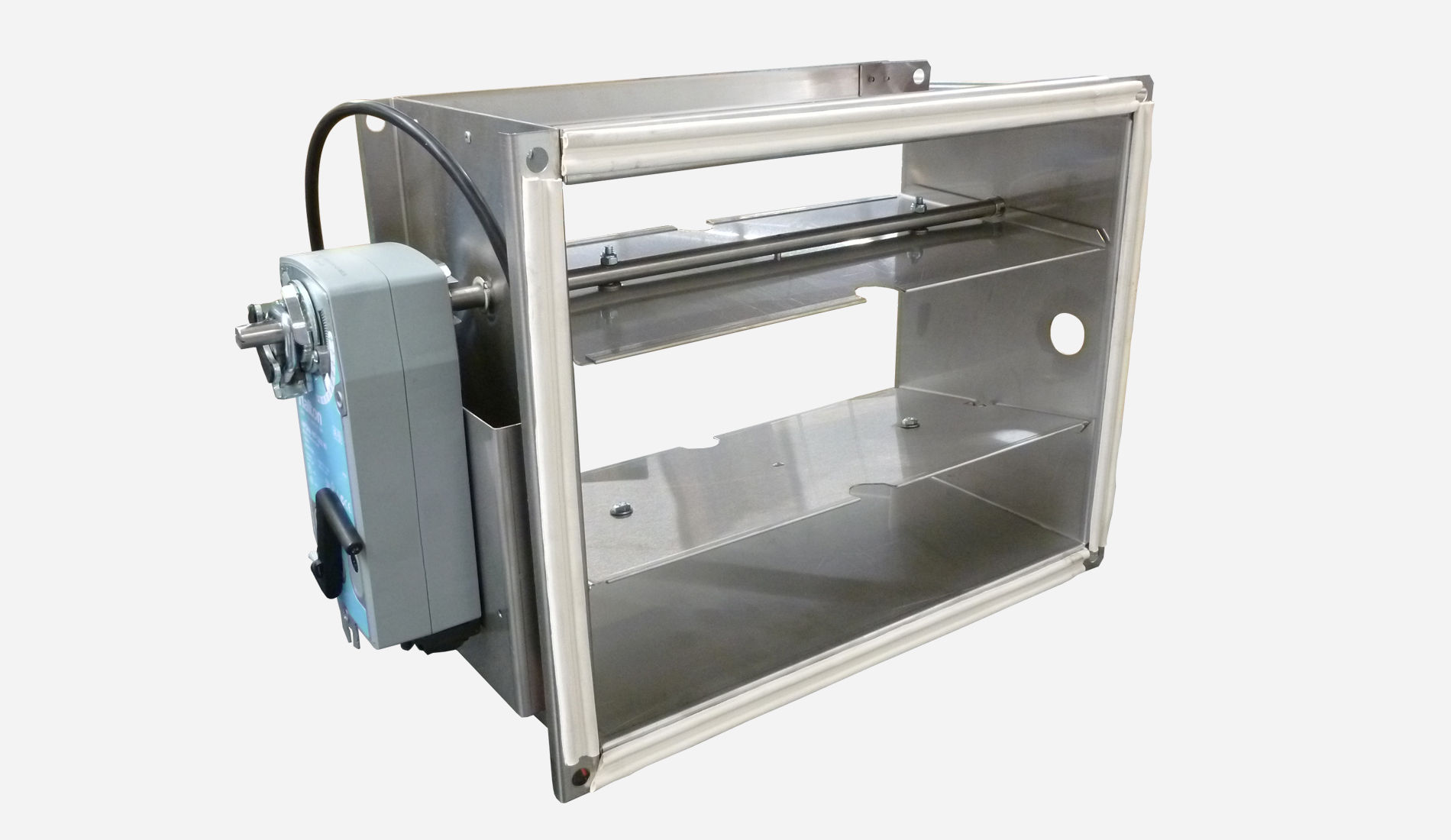
Halton Max MSB – Slim airflow management damper (VAV)
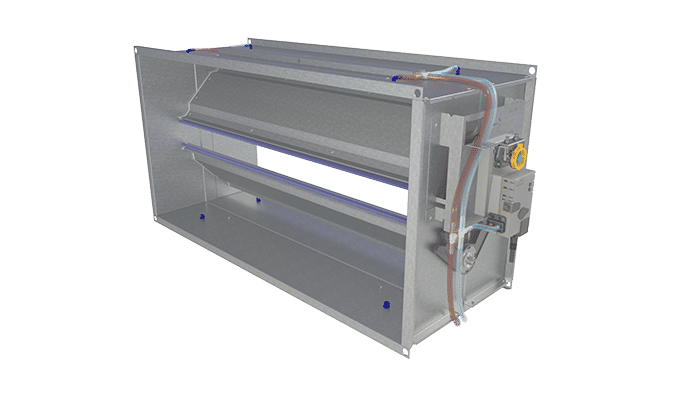
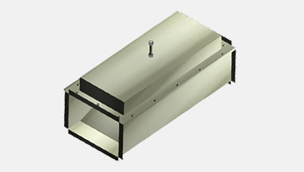
This slim VAV damper is ideal for renovation, corridors and other spaces where the height of the damper is a critical requirement.
So easy to install as no safety distance is required.
- Can be used in both air volume or air pressure control application
- Integrated sound attenuation
Overview
Slim damper, ideal for renovation, corridors and other spaces where the height of damper is critical. Easy to install as no safety distance is required.
Applications
- Variable (VAV) and constant (CAV) airflow control applications
- Supply and exhaust installations
Key features
- Rectangular low-profile airflow management damper
- Suitable for VAV supply or exhaust applications
- Can be installed without the need for straight duct lengths
- Highly accurate airflow measurement
- Can be used in both air volume or air pressure control applications
- Integrated sound attenuation
- Can be connected to Buildings Management System (BMS)
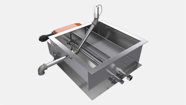
Operating principle
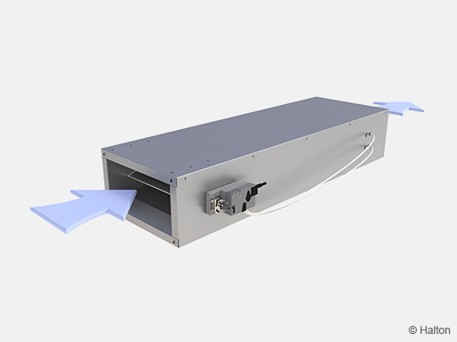
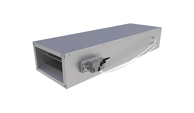
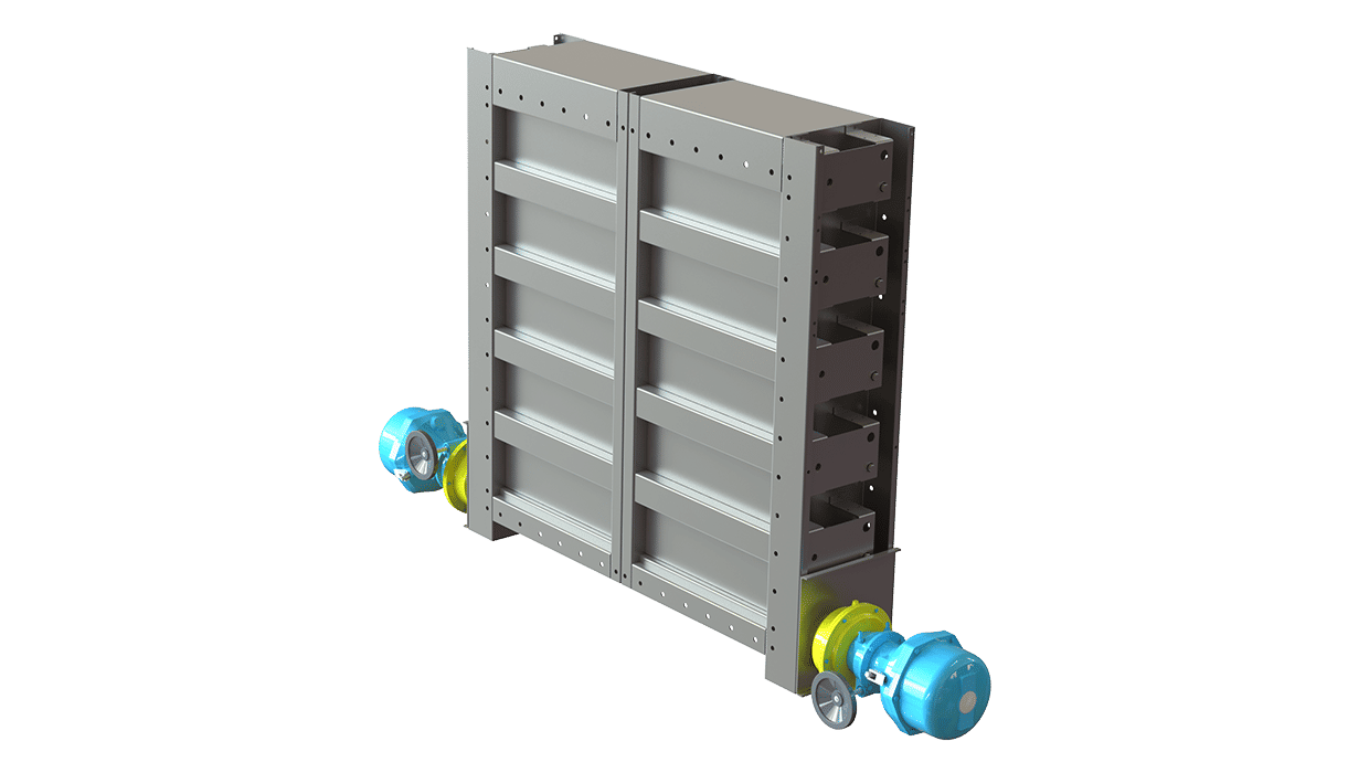
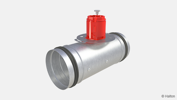
Fig.1. Halton Max MSB, supply
The Halton Max MSB includes a closed loop controller, comprising an aluminium differential pressure measuring probe, an actuator mounted on the damper blade spindle and a controller. This system allows the air volume to be accurately regulated independently of variations in upstream pressure. It can be used in a supply or exhaust application.
Measurements made by the differential pressure sensor are sent to the controller which compares these values with the required room setpoint value. The controller compares the actual values with the setpoint value and sends a signal to the actuator which adjusts the position of the damper to compensate for the difference.
It can be used in a supply or exhaust application. Measurements made by the differential pressure sensor are sent to the controller which compares these values with the required room setpoint value. The controller compares the actual values with the setpoint value and sends a signal to the actuator which adjusts the position of the damper to compensate for the difference. An analogue signal to alter the setpoint value can also be sent to the controller and the flow rate will then be adjusted to the new setpoint. Volume flow rates are regulated between the pre-set min. and max. values in the controller.
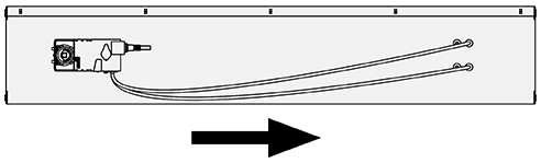
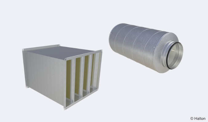
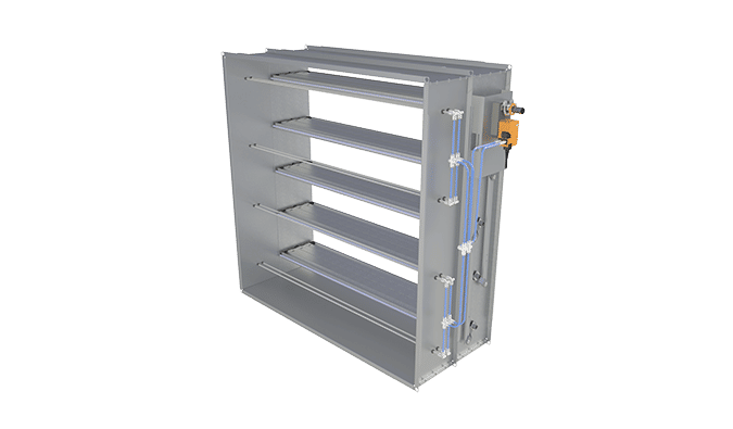
Fig.2. Halton Max MSB, supply
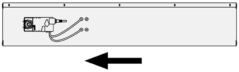
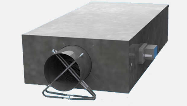
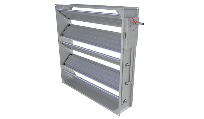
Fig.3. Halton Max MSB, exhaust
The Halton Max MSB is used for the following applications:
- Constant airflow
To get a stable airflow without influenced by the pressure variation ductwork - Variable airflow
The airflow is managed according the CO2 or occupancy in the room - Duct pressure
To get a stable pressure in the ductwork for specific terminal like diffuser, chilled beam that can be required a constant pressure.
Key technical data
| Description | Value |
| Duct connection sizes | W = 200, 300, 400, 600, 800 mm H = 150, 250 mm |
| Material | Galvanised steel |
| Air velocity range | 1 – 10 m/s |
| Operating range (ambient temperature) | 0-50 ℃ |
| Ambient relative humidity (non-condensing) | < 95% |
| Communication interface | Modbus RTU, analogue, MP-Bus, LON, BACnet MSTP |
| Maintenance | Maintenance-free |
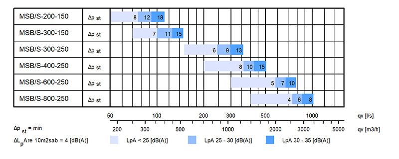
Quick selection
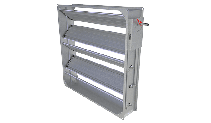
Structure and materials
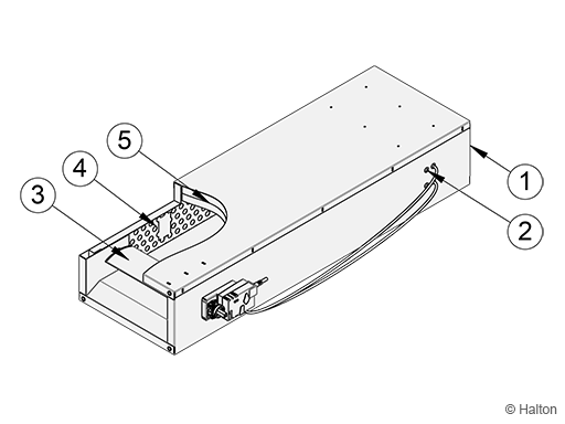
| No. | Part | Material |
| 1 | Plenum | Galvanised steel |
| 2 | Measurement probe | Aluminium |
| 3 | Blade | Aluminium |
| 4 | Perforated sheet | Perforated sheet |
| 5 | Insulation | Glasswool |
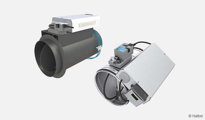
Control units
A range of actuators are available for various application needs.
All actuators include an integrated dynamic differential pressure sensor with a low bypass airflow rate through the sensor element. Therefore not to be used in highly contaminated environments. Airflow rate limits are set at the factory.
| Actuator | Notes | Torque [Nm] |
Damper size |
Communication interface |
Order code |
| EM | Analogue actuator Manufacturer: Belimo |
5 | (200-300)x150 | DC0..10V/2..10V | EM = LMV-D3-MF-F.1 HI (DC 0/2…10 V), 5 Nm |
| EK | Analogue actuator Manufacturer: Belimo |
10 | (300-800)x250 | DC0..10V/2..10V | EK = NMV-D3-MF-F.1 HI (DC 0/2…10 V), 10 Nm |
| EC | Actuator with NFC connectivity for mobile onsite parameter adjustment (Belimo Assistant App). Analogue or MPbus. Manufacturer: Belimo |
5 | (200-300)x150 | Belimo MP bus or 0..10V/2..10V |
EC = LMV-D3-MP (MP bus), 5 Nm |
| EE | Actuator with NFC connectivity for mobile onsite parameter adjustment (Belimo Assistant App). Analogue or MPbus. Manufacturer: Belimo |
10 | (300-800)x250 | Belimo MP bus or 0..10V/2..10V |
EE = NMV-D3-MP (MP bus), 10 Nm |
| EH | Analogue actuator Manufacturer: Siemens |
5 | (200-300)x150 | DC0..10V/ 2..10V |
EH = GDB181.1E/3 (DC 0/2…10 V), 5 Nm |
| EG | Analogue actuator Manufacturer: Siemens |
10 | (300-800)x250 | DC0..10V/ 2..10V |
EG = GLB181.1E/3 (DC 0/2…10V), 10 Nm |
| EV | Actuator with KNX Manufacturer: Siemens |
5 | (200-300)x150 | KNX communication |
EV = GDB181.1E/KN (KNX bus), 5 Nm |
| EW | Actuator with KNX Manufacturer: Siemens |
10 | (300-800)x250 | KNX communication |
EW = GLB181.1E/KN (KNX bus), 10 Nm |
| EB | Actuator with Modbus RTU (RS-485) Manufacturer: Siemens |
5 | (200-300)x150 | Modbus communication | EB = GDB181.1E/MO (Modbus RTU), 5 Nm |
| EF | Actuator with Modbus RTU (RS-485) Manufacturer: Siemens |
10 | (300-800)x250 | Modbus communication | EF = GLB181.1E/MO (Modbus RTU), 10 Nm |
| HM | Controller include actuator with LonWorks Manufacturer: Distech |
5 | (200-300)x150 | LonWorks communication | HM = ECL-VAV-S, HAV (LonWorks), 5Nm |
| HK | Modulating actuator from Belimo: Controller LonWorks Manufacturer: Distech |
10 | (300-800)x250 | LonWorks communication | HK = ECL-VAV-N, HAV + NM24A-SR (LonWorks), 10 Nm |
Dimensions and weight
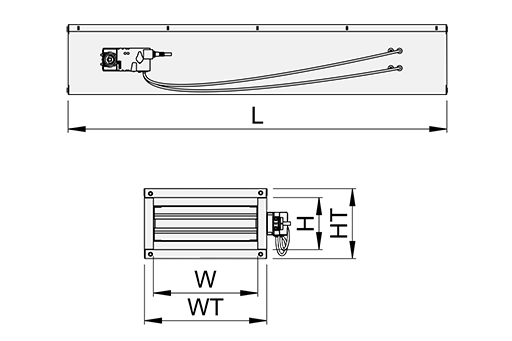
| Size | W | H | WT | HT | L | Weight [kg] |
| 200×150 | 200 | 150 | 255 | 205 | 1100 | 15.0 |
| 300×150 | 300 | 150 | 355 | 205 | 1100 | 21.0 |
| 300×250 | 300 | 250 | 355 | 305 | 1200 | 38.0 |
| 400×250 | 400 | 250 | 455 | 305 | 1200 | 40.0 |
| 600×250 | 600 | 250 | 655 | 305 | 1500 | 46.0 |
| 800×250 | 800 | 250 | 855 | 305 | 1500 | 57.0 |
Specification
The Halton Max MSB airflow management unit can be applied in both supply and exhaust Variable Air Volume applications. Its compact, low profile design permits installation into challenging spaces where access is limited or where room and false ceiling heights are restricted. The dynamic pressure measurement system allows an accurate measurement of the airflow without upstream safety distances.
The Halton Max MSB comprises:
• an airflow control damper blade
• an aluminium airflow differential pressure measurement probe installed centrally inside the plenum
• an integrated silencer
The pressure differential probe measures the average pressure across the whole surface, and from that accurately determines the actual volume of air passing through the unit. The position of the damper blade is then constantly calculated and adjusted by the actuator mounted on the spindle of the damper blade, in response to the measurements from the dynamic pressure sensor and electronic controller.
The selection of the VAV box is done according to the range of airflow it is designed to control based on performance data compiled from results of performance tests carried out in our Innovation Hubs and Laboratories. Each plenum is calibrated and the controls are pre-set at our factory to the minimum and maximum airflow conditions specified by the client. Factory pre-set parameters and project reference identification information are clearly marked on each unit. The acoustic properties of the Halton Max Slim Box are improved by the inclusion of a symmetrical attenuator containing Euroclass A2 s1 d0 high density mineral wool.
Minimum and maximum airflow values stated are indicative only and can differ by control type or brand, so please check with Halton prior to ordering.
Installation
The Dynamic Measuring System within the Halton Max MSB allows it to be installed directly after a T, elbow or reduction or even on to a main riser duct without affecting the accuracy of the air volume measurement.
Therefore, there is no requirement for safety distances.
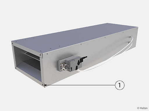
Key
1. Rivet nut M8
The Halton Max MSB is connected to the ductwork thank to the rivet nut M8 (1).
Wiring
The wiring must be carried out by professional technicians in accordance with local regulations. For the power supply, a safety-isolating transformer must be used.
Key
1 (G0) 24 VAC system neutral
2 (~) 24 VAC live
3 (Y) 2…10- or 0…10-VDC airflow setpoint signal input
5 (U) 2…10- or 0…10-VDC airflow feedback signal output
The wiring instructions are presented for following applications
| Example | Actuator | Application |
| 1A | CU=EM / EK / EC / EE | Typical variable airflow control application |
| 1B | CU=EM / EK / EC / EE | Overriding controls |
| 1C | CU=EM / EK / EC / EE | Example; variable airflow control with a room controller |
| 1D | CU=EM / EK / EC / EE | Example; variable airflow control with a building management system |
| 1E | CU=EM / EK / EC / EE | Example: parallel airflow control with a building management system |
| 3A | CU=EG | Typical variable airflow control |
| 3B | CU=EG | Position and constant airflow control |
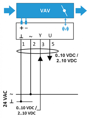
1A and 1B
CU = EM/EC (LMV-D3-MP/MF HI) or EK/EE (NMV-D3-MP/MF HI)
– typical application and overriding controls
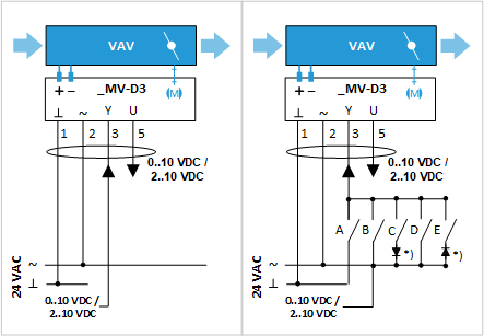
1A Typical variable airflow control application 1B Overrides All options
Key
VAV Halton Max Slim Box (MSB)
1 (G0) 24 VAC system neutral
2 (~) 24 VAC live
3 (Y) 2…10- or 0…10-VDC airflow setpoint signal input
5 (U) 2…10- or 0…10-VDC airflow feedback signal output
*) Diode 1N 4007
Operating mode
| 2…10 VAC | 0…10 VAC | A | B | C | D | E |
| Closed | qv_min | ON | ||||
| qv_min | qv_min | Off | Off | Off | Off | Off |
| Variable qv_min…qv_max |
Variable qv_min…qv_max |
Off | ON | Off | Off | Off |
| CLOSED | CLOSED | Off | Off | ON | Off | Off |
| qv_max | qv_max | Off | Off | Off | ON | Off |
| OPEN | OPEN | Off | Off | Off | Off | ON |
Shut-off with control signal w:
In addition to relay override command situations, the damper will be fully closed if:
- 0…10 VDC: the Halton Max MSB minimum airflow is set to 0% (0 l/s or 0 m3/h) and control signal w falls below 0.45 VDC
- 2…10 VDC : the Halton Max MSB control signal w falls below 0.5 VDC
- Both 0…10 VDC and 2…10 VDC: the airflow setpoint voltage falls below a value corresponding to an air velocity of less than 0.5 m/s
| Mode | Voltage of w, VDC |
Function |
| 0…10 VDC | 0.0…0.45 | Minimum airflow (closed if qv_min = 0%) |
| 0.5…10.0 | Modulating, qv_min … qv_max | |
| 10.0 | Maximum airflow | |
| 2…10 VDC | 0.0…0.5 | Damper closed |
| 0.5…2.0 | Minimum airflow | |
| 2.0…10.0 | Modulating, qv_min…qv_max | |
| 10.0 | Maximum airflow |
1C and 1D
CU = EM/EC (LMV-D3-MP/MF HI) or EK/EE (NMV-D3-MP/MF HI)
– variable airflow control with a room controller or a building management system
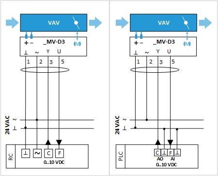
1C Room controller application 1D Building management system application
Key
VAV Halton Max MSB
1 (G0) 24 VAC system neutral
2 (~) 24 VAC live
3 (Y) 0…10-VDC airflow setpoint signal input
5 (U) 0…10-VDC airflow feedback signal output
RC Room controller
PLC Building management system
C (AO) Airflow setpoint control signal
F (AI) Actual airflow feedback input
1E
CU = EM/EC (LMV-D3-MP/MF HI) or EK/EE (NMV-D3-MP/MF HI)
– parallel airflow control with a building management system
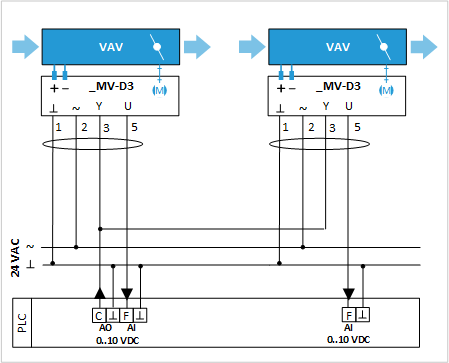
1E Parallel airflow control with building management system
Key
1 (G0) 24 VAC system neutral
2 (~) 24 VAC live
3 (Y) 0…10-VDC airflow setpoint signal input
5 (U) 0…10-VDC airflow feedback signal output
PLC Building management system
C (AO) Airflow setpoint control signal
F (AI) Actual airflow feedback input
3A and 3B
CU=EG (GLB181.1E/3)
– typical variable airflow control and position and constant airflow control
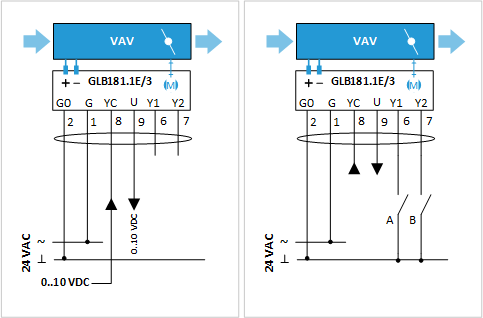
3A Typical airflow control application 3B Position and constant airflow control
Key
VAV Halton Max MSB
2 (G0) 24 VAC system neutral
1 (G) 24 VAC live
8 (YC) 2…10- or 0…10-VDC airflow setpoint signal input
9 (U) 2…10- or 0…10-VDC airflow feedback signal output
6 (Y1) Override input
7 (Y2) Override input
| Constant flow | A | B |
| CLOSED | Off | ON |
| Min. flow | Off | Off |
| Max. flow | ON | ON |
| OPEN | ON | Off |
Commissioning
The actual airflow rate can be calculated as a function of differential pressure at the measurement probe and the measurement probe k factor. The proper k factor can be found in the documentation supplied with the product and in the table below (supply and exhaust).
| Size | k factor (airflow in m3/h) |
k factor (airflow in l/s) |
| 200 x 150 | 67 | 18.5 |
| 300 x 150 | 100 | 28.0 |
| 300 x 250 | 225 | 62.5 |
| 400 x 250 | 300 | 83.5 |
| 600 x 250 | 450 | 125.0 |
| 800 x 250 | 600 | 166.5 |
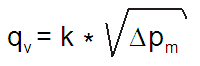
qv Actual airflow rate [l/s]
k k factor value
Δpm Differential pressure of measurement probe [Pa]
Order code
MSB-M-W-H; CU-SE-TF-ZT
| Main options | |
| M = Model | |
| S | Supply |
| E | Exhaust |
| W = Width of duct connection [mm] | 200, 300, 400, 600, 800 |
| H = Height of duct connection [mm] | 150, 250 |
| Other options and accessories | |
| CU = Control unit | |
| EM | LMV-D3-MF-F.1 HI (analogue), 5 Nm |
| EK | NMV-D3-MF-F.1 HI (analogue), 10 Nm |
| EC | LMV-D3-MP-F. HI (MP bus), 5 Nm |
| EE | NMV-D3-MP-F. HI (MP bus) 10 Nm |
| EH | GDB181.1E/3 (DC 0/2…10 V), 5 Nm |
| EG | GLB181.1E/3 (DC 0/2…10V), 10 Nm |
| EV | GDB181.1E/KN (KNX bus), 5 Nm |
| EW | GLB181.1E/KN (KNX bus), 10 Nm |
| EB | GDB181.1E/MO (Modbus RTU), 5 Nm |
| EF | GLB181.1E/MO (Modbus RTU), 10 Nm |
| ER | LMV-D3-KNX (KNX bus), 5 Nm |
| ES | NMV-D3-KNX (KNX bus), 10 Nm |
| ET | LMV-D3-MOD (Modbus RTU), 5 Nm |
| EU | NMV-D3-MOD (Modbus RTU), 10 Nm |
| HM | ECL-VAV-S, HAV (LonWorks), 5Nm |
| HK | ECL-VAV-N + NM24A-SR, HAV (LonWorks),10Nm |
| SE = Sensors | |
| NA | Not assigned |
| DS1 | Duct sensor (TCO2, Duct CO2) |
| P1 | Differential pressure transmitter (HDP-PE) |
| TF = Transformer | |
| NA | Not assigned |
| TF1 | 230/24 transformer (35VA) |
| ZT = Tailored product | |
| N | No |
| Y | Yes (ETO) |
Order code example
MSB-S-200-150; CU=EM, SE=NA, TF=TF1, ZT=N
Downloads
"*" indicates required fields
ABD – Automated Balancing Damper for kitchen ventilation (CE)
product
ABD – Automatic balancing damper for kitchen ventilation (ETL)
product
CID-01 – Zero leakage isolation damper
product
Halton BOX – Airflow management unit (VAV)
product
Halton Max MDC – Zone control damper for Halton Workplace system
product
Halton Max MLC – Airflow management damper (VAV)
product
Halton Max MOC – Airflow management damper (VAV)
product
Halton Max MOS – Airflow management damper (VAV)
product
Halton Max MSB – Slim airflow management damper (VAV)
product
Halton Max MUC – Ultrasound airflow management damper (VAV)
product

Halton PRA – Airflow management damper (CAV)
product
Halton PTS – Airflow management damper (single-blade)
product
Halton RMC – Airflow management damper (CAV)
product
Halton SA – Sound attenuator
product
Halton UKV – Airflow management damper (VAV)
product
Halton UTK – Multi-blade airflow management damper (CAV)
product
Halton UTT – Multi-blade airflow management damper (CAV)
product

Halton Vita VLR – Room airflow controller for Halton Vita Lab solutions
product
Halton Vita VLS – Fume cupboard controller for Halton Vita Lab solutions
product
KBD – Exhaust hood balancing damper (ETL)
product