Product / UTK
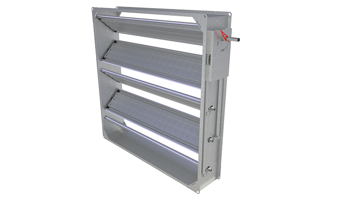
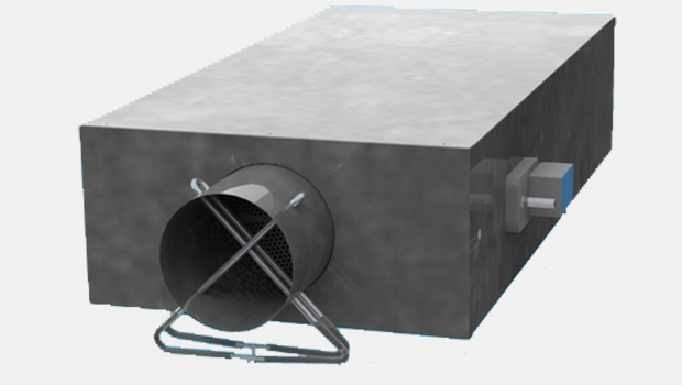
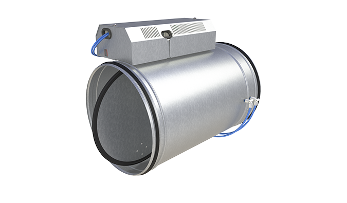
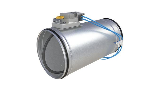
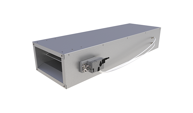
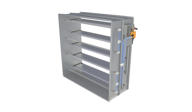
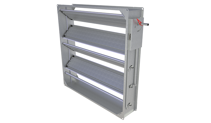
Halton UTK – Multi-blade airflow management damper
Available in various rectangular modular sizes.
The shut-off tightness is class 1 according to EN 1751.
- Shut-off, adjustment, balancing, adjustment or control damper with opposed blade construction
- Tightness in closed position fulfills EN 1751 class 1 requirements
Overview
- Shut-off, adjustment, balancing or control damper with opposed blade construction
- Tightness in closed position fulfills EN 1751 class 1 requirements
- Classification of casing leakage EN 1751 class B
- Temperature operation range up to +100°C, optionally up to +200°C
- Galvanised steel design
Product models and accessories
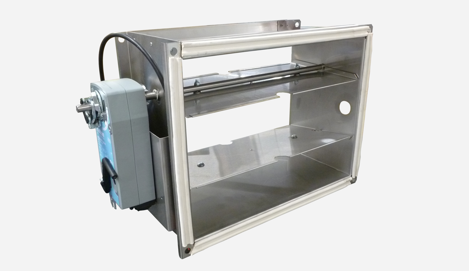
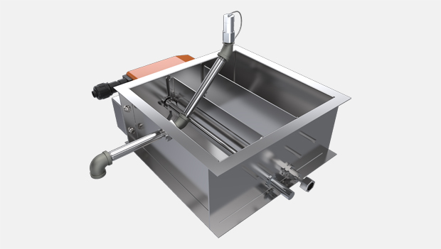
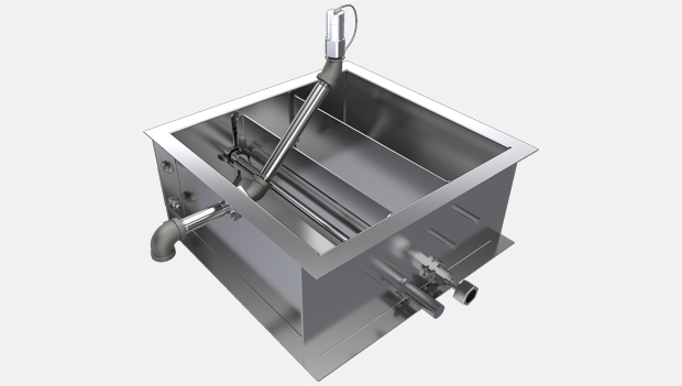
- Model with stainless steel (AISI 316L) design
- Model with insulated casing
- Model with heat-proof design
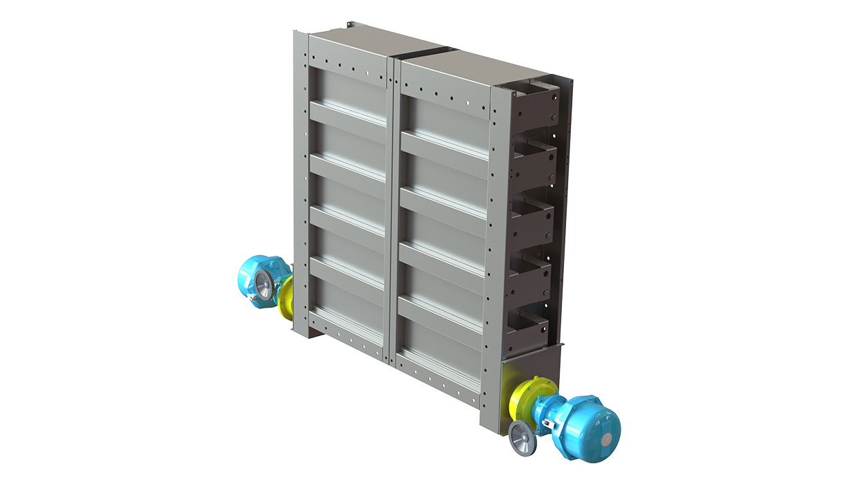
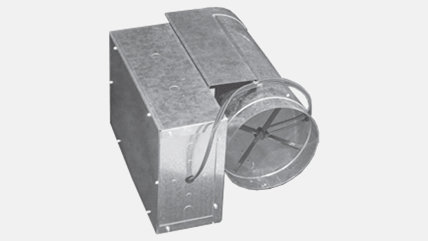
- Circular duct connections
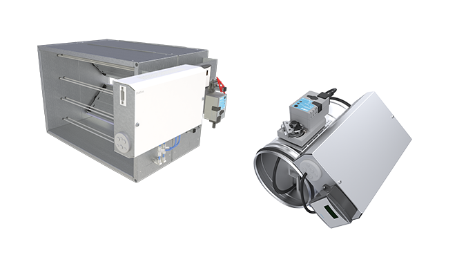
- Several actuator options
Dimensions
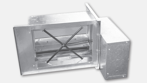
Halton UTK with rectangular connections
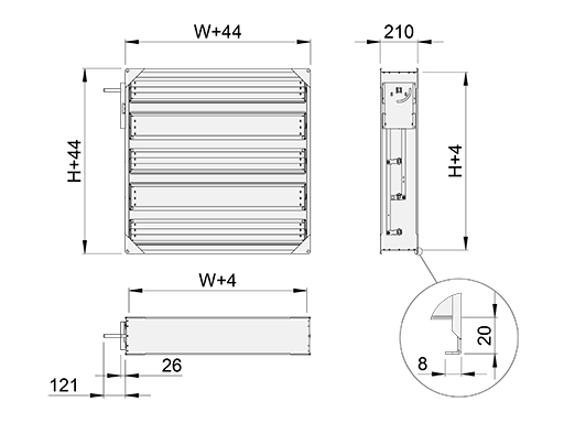
| W | H |
| 100, 200, …, 2400 | 100, 200, …, 2400 |
Halton UTK with circular connections (CT=D1 or CT=D2)
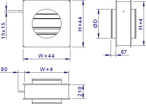
| ØD | W x H [mm] |
| 100 | 150×150 |
| 125 | 150×150 |
| 160 | 200×200 |
| 200 | 200×200 |
| 250 | 250×250 |
| 315 | 300×300 |
| 400 | 400×400 |
| 500 | 500×500 |
| 630 | 600×600 |
| 710 | 800×800 |
| 800 | 800×800 |
| 1000 | 1000×1000 |
| 1250 | 1300×1300 |
Material
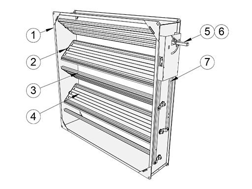
| No. | Part | Material | Note |
| 1 | Casing | Galvanised steel | Stainless steel (AISI 316) also available |
| 2 | Blade bearings |
Alloy of polyamide and molybdenum suphide (plastic). | Also available: Stainless steel (AISI 304) (BM=SS) Acid proof steel (AISI 316) (BM=AS) |
| 3 | Blade gaskets |
Silicone | (sandwich design). Acid proof steel (AISI 316L) also available |
| 4 | Blades | Galvanised steel | Circular connections |
| 5 | Rectangular drive shaft (15x15mm) |
Galvanised steel | In conjunction with standard plastic bearings (BM=ST) Acid proof steel (AISI 316) also available (BM=ST) |
| 6 | Round drive shaft (Ø15mm) |
Acid proof steel | In conjunction with AISI 316 or bronze bearings (BM=AS/SS/BR) |
| 7 | Lever mechanism | Galvanised steel | Acid proof steel (AISI 316L) also available |
Shaft types and dimensions
Depending on the choice of bearing material, the damper will be equipped with a round or square axle.
On Halton UTK/C dampers with standard bearings (BE=ST) , the damper will be equipped with a square 15×15 mm galvanised steel axle.
On heatproof design Halton UTK/C dampers, and on all dampers with AISI 316/304 or bronze JN5 bearings (BM=AS, BM=SS or BM=BR) a round Ø15mm AISI 316 stainless steel axle will be used.
Accessories
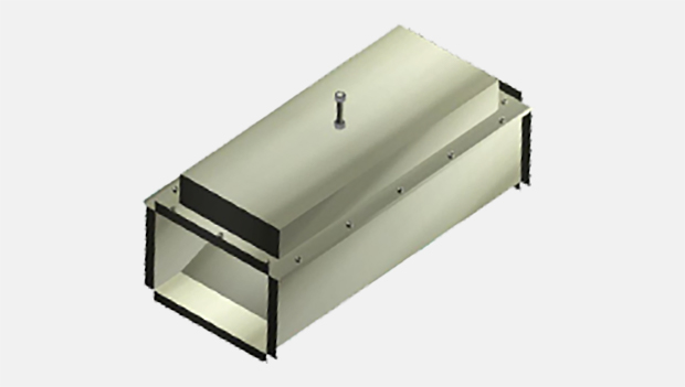
The product models MD=I and MD=J have a double sheet casing with mineral wool insulation. The insulation thickness is 20 mm.
The Halton UTK damper is available equipped with either manual adjustment or actuator operation.
The adjustment and control arrangement options are:
| Adjustment and control options | Code | Note |
| Manual handle adjustment | MO = MA | |
| Manual extension bar adjustment | AC = BA | Handle extension arrangement |
| Actuator operation | MO= | See tables below |
The damper actuator is selected from the list below according to the
operating voltage, control arrangement and the required torque of the damper.
The torque of the selected actuator can be higher than the required torque of the damper.
Actuator options
NM-models Torque, damper size … 10 Nm A<1.2 m 2
Manual override operation,mechanical position limit
| Actuator type | Code MO |
Control arrangement | Operating voltage |
Power consumption |
| NM24A | C1 | On-off, 3-point | AC/DC 24 V | 3,5 VA |
| NM230A | C2 | On-off, 3-point | AC 230 V | 5,5 VA |
| NM24A-SR | C3 | Control signal DC 0…10 V | AC 24 V | 4 VA |
BF-models Torque, damper size …18 Nm / 12 Nm (A<2.5 m2)
Spring return, manual operation, position limit
| Actuator type | Code MO |
Control arrangement | Operating voltage |
Power consumption |
| BF24 | E1 | On-off, 2 auxiliary switches | AC/DC 24 V | 10 VA |
| BF230 | E3 | On-off, 2 auxiliary switches | AC 230 V | 12.5 VA |
| BF120 | E7 | On-off, 2 auxiliary switches | AC 120 V | 12.5 VA |
SF-models Torque, damper size … 20 Nm (A<4 m2)
Spring return, manual operation, position limit
| Actuator type | Code MO |
Control arrangement | Operating voltage |
Power consumption |
| SF24A | A6 | On-off | AC/DC 24 V | 7,5 VA |
| SF24A-S2 | A7 | On-off, 2 auxiliary switches | AC/DC 24 V | 7,5 VA |
| SFA | A8 | On-off | AC 24…240V / DC 24….125 V | 18 VA |
| SFA-S2 | A9 | On-off, 2 auxiliary switches | AC 24…240V / DC 24….125 V | 18 VA |
| SF24A-SR | A0 | Control modulating DC 2…10 V, Position feedback 2…10 V | AC/DC 24 V | 7 VA |
| SF24A-MP | A11 | Control modulating, communicative 2…10 V, Position feedback 2…10 V variable | AC/DC 24 V | 11 VA |
SM-models Torque, damper size … 18 Nm A<3.3 m2
Manual override operation, mechanical position limit
| Actuator type | Code MO |
Control arrangement | Operating voltage |
Power consumption |
| SM24A | A1 | On-off, 3-point | AC/DC 24 V | 4 VA |
| SM24A-S | A2 | On-off, 3-point, 1 auxiliary switch |
AC/DC 24 V | 4 VA |
| SM230A | A3 | On-off, 3-point | AC 230 V | 6 VA |
| SM230A-S | A4 | On-off, 1-wire control, 3-point, 1 auxiliary switch | AC 230 V | 6 VA |
| SM24A-SR | A5 | Control signal DC 2…10 V, Position feedback 2…10V | AC/DC 24 V | 4 VA |
| SM24A-MA | M3 | Control modulating 4…20 mA, Position feedback 2…10 V | AC/DC 24 V | 9 VA |
GM-models Torque, damper size …40 Nm (A<6 m2)
Manual override operation
| Actuator type | Code MO |
Control arrangement | Operating voltage |
Power consumption |
| GM24A | G1 | On-off, 3-point |
AC/DC 24 V | 6 VA |
| GM230A | G2 | On-off, 3-point |
AC 230 V | 9 VA |
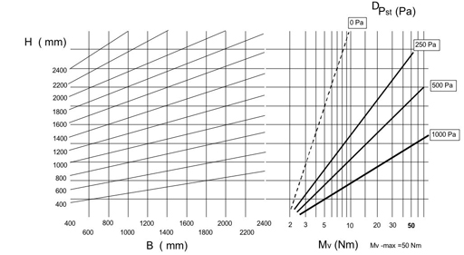
Required torque for Halton UTK-damper actuator
Function
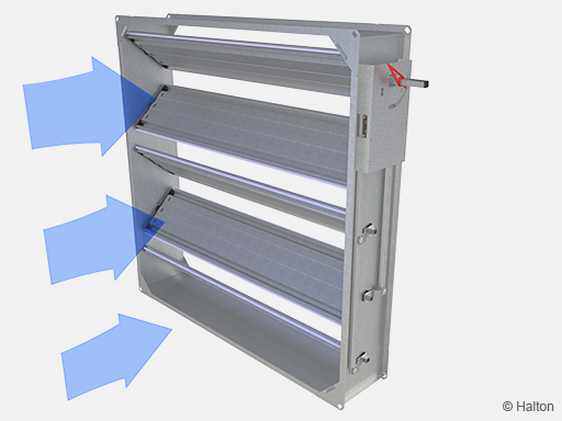
The Halton UTK dampers are used to shut off, adjust or control airflow in ductwork in applications where damper leakage does not have significant importance.
In the closed position the Halton UTK damper leakage class is 1 in accordance with the EN1751 standard.
In the open position the blades are turned in the direction of flow and do not cause significant pressure loss.
Damper sizes conform with the international standards EN 1505, EN1506 and ISO 1707 for rectangular and circular ducts.
The maximum operation temperature of a standard damper is +100°C (for optional models +200°C).
Installation
Install the damper in the ductwork with the blades in horizontal or vertical position.
Fasten the damper in the ductwork using slip joints.
Optional models enable fastening the damper to duct flange by using bolts.
Drill holes in the damper flange if necessary (options L1 & L2).
Use a seal between the flanges in order to tighten the seam.
Fasten the circular connections by riveting or screwing.
Specification
The casing and blades are made from galvanised steel (or stainless steel AISI 316).
The blade gaskets are of silicon (or EPDM- rubber).
The drive shaft socket is of galvanised steel with self-lubricating slide bearings.
The bearing shall is from an alloy of polyamide and molybdenum sulphide (or stainless steel AISI 316 or stainless steel AISI 304 or bronze).
The damper is installed into rectangular ductwork in compliance with EN 1751, or in circular ducts D=100 … 1250 mm in accordance with EN 1751.
The damper meets the tightness requirements of EN 1751 class 1.
The casing of the damper meets the tightness requirements of EN 1751 class B.
The damper is suitable for either manual adjustment or actuator operation.
Product code
UTK/S-W-H-D, CT-SF-MA-MD-BM-MO-AC-ZT
S = Type of duct connections
R Rectangular connections
C Circular connections
W = Width (mm)
100,+1,..,2400
H = Height (mm)
100,+1,..,2400
D = Connection size (for circlular model, C)
100, 125, 160, 200, 250, 315, 400, 500, 630, 710, 800, 1000, 1250
Other options and accessories
CT = Type of circular connection
D2 2 circular connections
D1 1 circular connection
SF = Flange option
NA Slip joints
L1 Slip joints + flange connection
L2 Flange connection, both sides
R2 Flange connection, both sides with holes
MA = Material
CS Steel
AS Stainless steel (EN 1.4404/AISI 316L)
MD = Model
N Standard
H Heat-proof
I Insulated
J Heat-proof and insulated
BM = Bearing material
ST Plastic
AS Stainless steel (AISI 316)
SS Stainless steel (AISI 304)
BR Bronze (JN5)
MO = Actuator type
NA Not assigned
MA Manual handle
E1 BF24 (no fuse), 24V, 18 Nm
E3 BF230 (no fuse), 230V, 18 Nm
E7 BF120 (no fuse), 120V, 18 Nm
P0 Pneumatic, Rot.AT101
A1 SM24A (on-off), 24V, 20 Nm
A2 SM24A-S (on-off), 24V, 20 Nm
A3 SM230A (on-off), 230V, 20 Nm
A4 SM230A-S (on-off), 230V, 20 Nm
A5 SM24A-SR (modulating), 24V, 20 Nm
M3 SM24A-MA (modulating), 24V, 20 Nm
A6 SF24A (on-off), 24V, 20 Nm
A7 SF24A-S2 (on-off), 24V, 20 Nm
A8 SFA (on-off), 24-230V, 20 Nm
A9 SFA-S2 (on-off), 24-230V, 20 Nm
A0 SF24A-SR (modulating), 24V, 20 Nm
A11 SF24A-MP (modulating), 24V, 20 Nm
C1 NM24A (on-off), 24V, 10 Nm
C2 NM230A (on-off), 230V, 10 Nm
C3 NM24A-SR (modulating), 24V, 10 Nm
G1 GM24A (on-off), 24V, 40 Nm
G2 GM230A (on-off), 230V, 40 Nm
AC = Accessories
BA Bar adjustment
S4 S2A Auxiliary switch
L1 Limit switch, 1 pc (IP65)
L2 Limit switch, 2 pcs (IP65)
AR Position indication arrow
ZT = Tailored product
N No
Y Yes (ETO)
Code example
UTT/R-100-100, SF=NA, MA=CS, MD=N, BM=ST, MO=MA, ZT=N
