Product / UTT
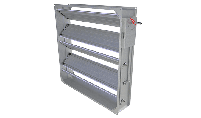
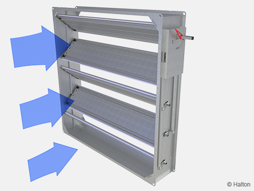
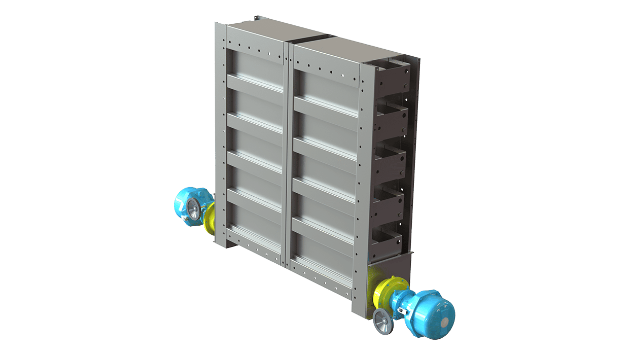
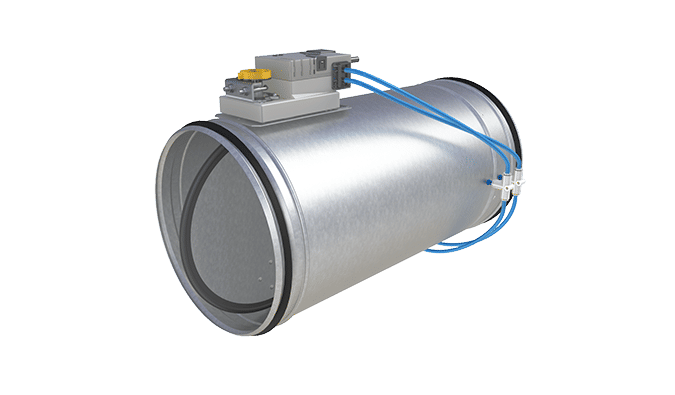
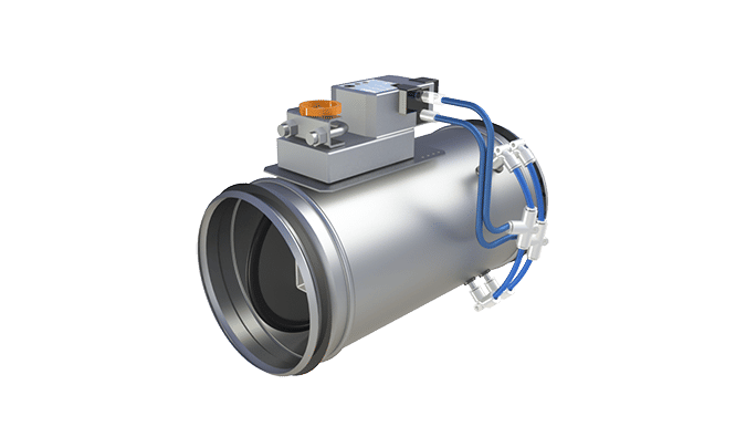
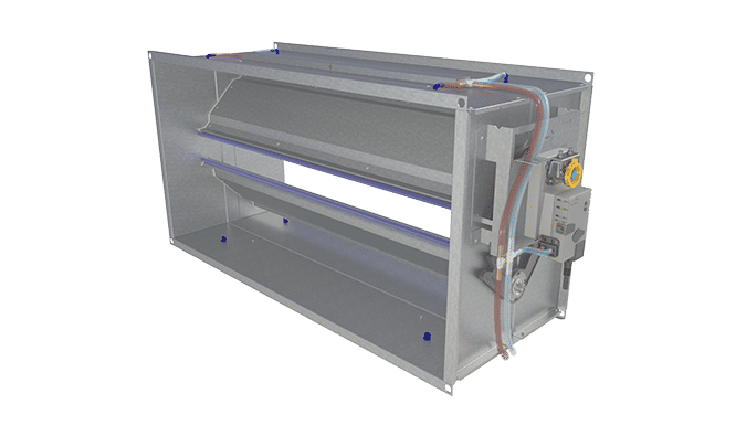
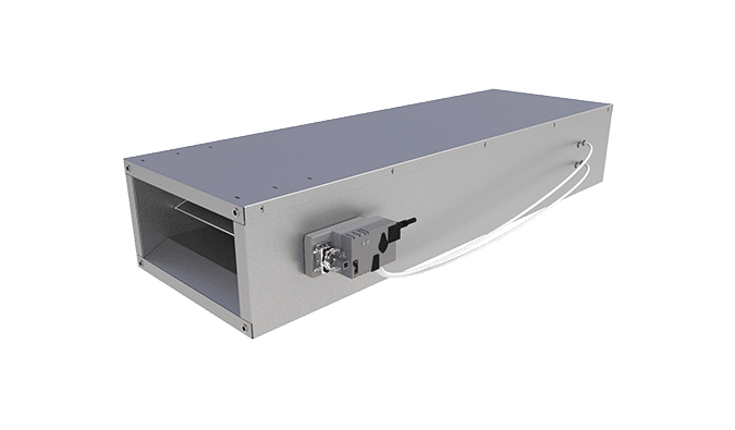
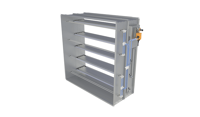
Halton UTT – Multi-blade airflow management damper (CAV)
Rectangular tight shut-off and balancing damper available with various modular construction and sizes.
The shut-off class 3 according to EN 1751.
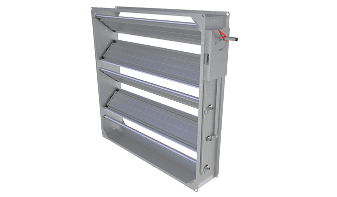
- Shut-off and balancing damper for outdoor air intake and exhaust air with opposed blade design
- Damper blades comprise thermal insulation
Overview
- Shut-off and balancing damper for outdoor air intake and exhaust air with opposed blade design
- Damper blades comprise thermal insulation
- Tightness in closed position fulfills EN 1751 class 3 requirements
- Temperature operation range up to +100°C, optionally up to +200°C
- Galvanised steel design
- Classification of casing leakage EN 1751 class B
Product models and accessories
- Model with stainless steel /acid-proof steel (AISI 316L) design.
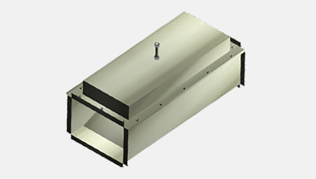
- Model with insulated casing
- Model with heat-proof design
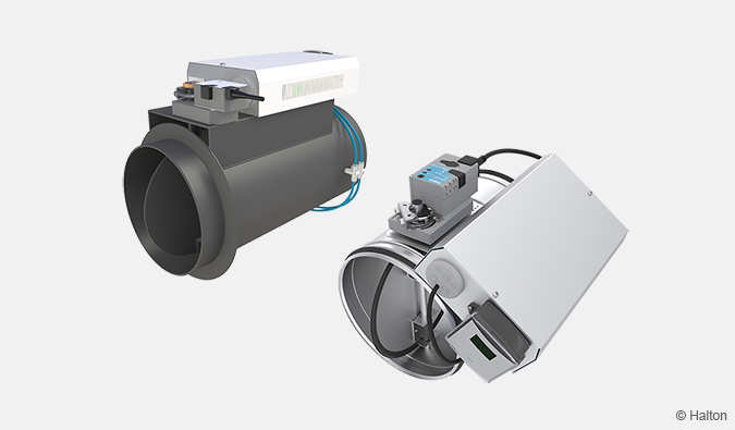
- Circular duct connections
- Several actuator options
Dimensions and weight
Models with rectangular connections
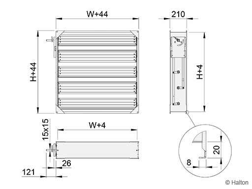
| W | H |
| 100, 200, …, 2400 | 100, 200, …, 2400 |
Models with circular connections (D1 or D2)
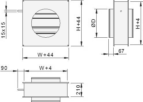
| ØD | W x H |
| 100 | 150×150 |
| 125 | 150×150 |
| 160 | 200×200 |
| 200 | 200×200 |
| 250 | 250×250 |
| 315 | 300×300 |
| 400 | 400×400 |
| 500 | 500×500 |
| 630 | 600×600 |
| 710 | 800×800 |
| 800 | 800×800 |
| 1000 | 1000×1000 |
| 1250 | 1300×1300 |
Weight [kg]
Weight presented without actuator. Basic actuator weight about 1 kg.
| H | W | |||||||||||
| 100 | 200 | 300 | 400 | 500 | 600 | 700 | 800 | 900 | 1000 | 1100 | 1200 | |
| 200 | 3 | 3 | 4 | 5 | 6 | 7 | 7 | 8 | 9 | 9 | 10 | 16 |
| 300 | 4 | 5 | 6 | 7 | 7 | 8 | 9 | 10 | 11 | 11 | 12 | 19 |
| 400 | 5 | 6 | 6 | 7 | 8 | 9 | 10 | 11 | 12 | 13 | 13 | 20 |
| 500 | 5 | 6 | 7 | 8 | 9 | 10 | 11 | 12 | 13 | 14 | 15 | 22 |
| 600 | 6 | 7 | 8 | 9 | 11 | 12 | 13 | 14 | 15 | 16 | 17 | 24 |
| 700 | 7 | 8 | 9 | 10 | 11 | 13 | 14 | 15 | 16 | 18 | 19 | 26 |
| 800 | 8 | 9 | 10 | 12 | 13 | 14 | 16 | 17 | 18 | 20 | 21 | 28 |
| 900 | 8 | 10 | 11 | 12 | 14 | 15 | 17 | 18 | 20 | 21 | 23 | 30 |
| 1000 | 9 | 11 | 12 | 14 | 15 | 17 | 18 | 20 | 22 | 23 | 25 | 32 |
| 1100 | 10 | 11 | 13 | 15 | 16 | 18 | 20 | 21 | 23 | 25 | 26 | 34 |
| 1200 | 11 | 12 | 14 | 16 | 18 | 19 | 21 | 23 | 25 | 27 | 28 | 36 |
| 1300 | 11 | 13 | 15 | 17 | 19 | 21 | 22 | 24 | 26 | 28 | 30 | 38 |
| 1400 | 12 | 14 | 16 | 18 | 20 | 22 | 24 | 26 | 28 | 30 | 32 | 40 |
| 1500 | 13 | 15 | 17 | 19 | 21 | 23 | 25 | 27 | 30 | 32 | 34 | 42 |
| 1600 | 14 | 16 | 18 | 20 | 22 | 25 | 27 | 29 | 31 | 34 | 36 | 44 |
| 1700 | 14 | 16 | 19 | 21 | 23 | 26 | 28 | 30 | 33 | 35 | 38 | 46 |
| 1800 | 15 | 17 | 20 | 22 | 25 | 27 | 30 | 32 | 35 | 37 | 40 | 48 |
| 1900 | 16 | 18 | 21 | 23 | 26 | 28 | 31 | 34 | 36 | 39 | 41 | 50 |
| 2000 | 16 | 19 | 22 | 25 | 27 | 30 | 33 | 35 | 38 | 41 | 43 | 52 |
| 2100 | 17 | 20 | 23 | 25 | 28 | 31 | 34 | 37, | 39 | 42 | 45 | 54 |
| 2200 | 18 | 21 | 24 | 27 | 30 | 33 | 36 | 38 | 41 | 44 | 47 | 56 |
| 2300 | 19 | 22 | 25 | 28 | 31 | 34 | 37 | 40 | 43 | 46 | 49 | 58 |
| 2400 | 20 | 23 | 26 | 29 | 32 | 35 | 38 | 42 | 45 | 49 | 51 | 60 |
| H | W | |||||||||||
| 1300 | 1400 | 1500 | 1600 | 1700 | 1800 | 1900 | 2000 | 2100 | 2200 | 2300 | 2400 | |
| 200 | 17 | 17 | 18 | 21 | 21 | 22 | 23 | 25 | 26 | 27 | 27 | 28 |
| 300 | 20 | 20 | 21 | 24 | 25 | 26 | 26 | 29 | 30 | 31 | 32 | 32 |
| 400 | 21 | 22 | 23 | 26 | 27 | 27 | 28 | 31 | 32 | 33 | 34 | 35 |
| 500 | 23 | 24 | 25 | 28 | 29 | 30 | 31 | 34 | 35 | 36 | 37 | 38 |
| 600 | 25 | 26 | 27 | 31 | 32 | 33 | 34 | 37 | 38 | 39 | 40 | 41 |
| 700 | 27 | 28 | 29 | 33 | 34 | 35 | 36 | 40 | 41 | 42 | 43 | 44 |
| 800 | 29 | 31 | 32 | 35 | 37 | 38 | 39 | 43 | 44 | 45 | 47 | 48 |
| 900 | 31 | 33 | 34 | 38 | 39 | 40 | 42 | 45 | 47 | 48 | 50 | 51 |
| 1000 | 34 | 35 | 37 | 40 | 42 | 43 | 45 | 49 | 50 | 52 | 53 | 55 |
| 1100 | 35 | 37 | 39 | 42 | 44 | 46 | 47 | 51 | 53 | 54 | 56 | 58 |
| 1200 | 38 | 40 | 41 | 45 | 47 | 49 | 51 | 54 | 56 | 58 | 60 | 62 |
| 1300 | 40 | 41 | 43 | 47 | 49 | 51 | 53 | 57 | 59 | 61 | 63 | 65 |
| 1400 | 42 | 44 | 46 | 50 | 52 | 54 | 56 | 60 | 62 | 64 | 66 | 68 |
| 1500 | 44 | 46 | 48 | 52 | 54 | 56 | 59 | 63 | 65 | 67 | 69 | 71 |
| 1600 | 46 | 48 | 51 | 55 | 57 | 59 | 62 | 66 | 68 | 70 | 73 | 75 |
| 1700 | 48 | 50 | 53 | 57 | 59 | 62 | 64 | 69 | 71 | 73 | 76 | 78 |
| 1800 | 50 | 53 | 55 | 60 | 62 | 65 | 67 | 72 | 74 | 77 | 79 | 82 |
| 1900 | 52 | 55 | 57 | 62 | 65 | 67 | 70 | 74 | 77 | 79 | 82 | 85 |
| 2000 | 55 | 57 | 60 | 65 | 67 | 70 | 73 | 78 | 80 | 83 | 86 | 88 |
| 2100 | 56 | 59 | 62 | 67 | 70 | 72 | 75 | 80 | 83 | 86 | 89 | 91 |
| 2200 | 59 | 62 | 65 | 70 | 73 | 76 | 78 | 83 | 86 | 89 | 92 | 95 |
| 2300 | 61 | 64 | 67 | 72 | 75 | 78 | 81 | 86 | 89 | 92 | 95 | 98 |
| 2400 | 63 | 66 | 69 | 75 | 78 | 81 | 84 | 89 | 92 | 95 | 99 | 102 |
| ØD | UTT/D1 | UTT/D2 | ØD | UTT/D1 | UTT/D2 |
| 160 | 4 | 4 | 500 | 12 | 15 |
| 200 | 4 | 5 | 630 | 17 | 21 |
| 250 | 5 | 6 | 800 | 24 | 30 |
| 315 | 7 | 9 | 1000 | 33 | 43 |
| 400 | 9 | 11 | 1250 | 52 | 67 |
Structure and Materials
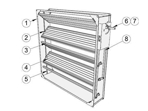
| No. | Part | Material | Note |
| 1 | Casing | Galvanised steel | Acid proof steel (AISI 316L) also available |
| 2 | Blade bearings | Alloy of polyamide and molybdenum suphide (plastic BM=ST). | Also available: |
| Stainless steel (AISI 304) (BM=SS) | |||
| Acid proof steel (AISI 316) (BM=AS) | |||
| Bronze JN5 (BM=BR) | |||
| 3 | Blade gaskets | Silicone | Heat-proof model: LTE silicone |
| 4 | Blades | Galvanised steel | (sandwich design). Acid proof steel (AISI 316L) also available |
| 5 | Gasket inside the casing | Silicone | Only tight UTT and UTX dampers. Gasket fixed in an aluminium profile |
| 6 | Rectangular drive shaft (15x15mm) | Galvanised steel | In conjunction with standard plastic bearings (BM=ST) |
| Acid proof steel (AISI 316) also available (BM=ST) | |||
| 7 | Round drive shaft (ø15mm) | Acid proof steel | In conjunction with AISI 316 or bronze bearings (BM=AS/SS/BR) |
| 8 | Lever mechanism | Galvanised steel | Acid proof steel (AISI 316L) also available |
Shaft types and dimensions
Depending on the choice of bearing material, the damper will be equipped with a round or square axle.
On Halton UTT/R dampers with standard bearings (BE=ST) , the damper will be equipped with a square 15×15 mm galvanised steel axle.
On heatproof design Halton UTT/R dampers, and on all dampers with AISI316/304 or bronze JN5 bearings (BM=AS, BM=SS or BM=BR) a round Ø15mm AISI 316 stainless steel axle will be used.
Accessories
The product models MD=I and MD=J have a double sheet casing with mineral wool insulation. The insulation thickness is 20 mm.
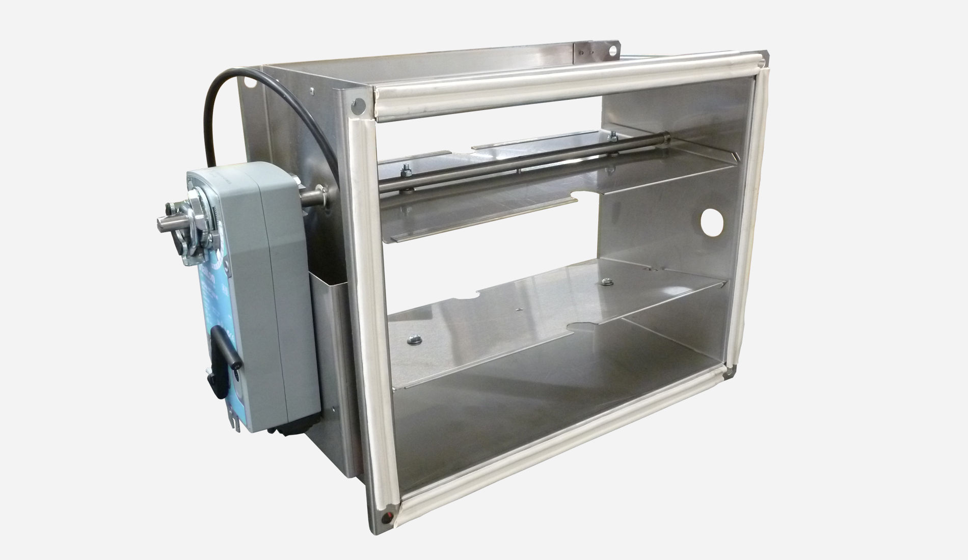
The Halton UTT damper is available equipped with either manual adjustment or actuator operation.
The adjustment and control arrangement options are:
| Adjustment and control options | Code | Note |
| Manual handle adjustment | MO = MA | |
| Manual extension bar adjustment | AC = BA | Handle extension arrangement |
| Actuator operation | MO= | See tables below |
The damper actuator is selected from the list below according to the
operating voltage, control arrangement and the required torque of the damper.
The torque of the selected actuator can be higher than the required torque of the damper.
Standard actuator options
NM-models
Torque, damper size … 10 Nm (A<1.2 m2)
Manual override operation,mechanical position limit
| Actuator type | Code MO | Control arrangement | Operating voltage | Power consumption |
| NM24A | C1 | On-off, 3-point | AC/DC 24 V | 3,5 VA |
| NM230A | C2 | On-off, 3-point | AC 230 V | 5,5 VA |
| NM24A-SR | C3 | Control modulating DC 2…10 V, Position feedback 2…10 V | AC 24 V | 4 VA |
BFN-models
Torque, damper size … 9 Nm (A<1.2 m2)
Spring return, manual operation, position limit
| Actuator type | Code MO | Control arrangement | Operating voltage | Power consumption |
| BFN24-HL | M1 | On-off, 2 auxiliary switches | AC/DC 24 V | 6 VA |
| BFN230-HL | M2 | On-off, 2 auxiliary switches | AC 230 V | 10 VA |
BF-models
Torque, damper size …18 Nm / 12 Nm (A<2.5 m2)
Spring return, manual operation, position limit
| Actuator type | Code MO | Control arrangement | Operating voltage | Power consumption |
| BF24 | E1 | On-off, 2 auxiliary switches | AC/DC 24 V | 10 VA |
| BF230 | E3 | On-off, 2 auxiliary switches | AC 230 V | 12,5 VA |
| BF120 | E7 | On-off, 2 auxiliary switches | AC 120 V | 12,5 VA |
SF-models
Torque, damper size … 20 Nm (A<4 m2)
Spring return, manual operation, position limit
| Actuator type | Code MO | Control arrangement | Operating voltage | Power consumption |
| SF24A | A6 | On-off | AC/DC 24 V | 7,5 VA |
| SF24A-S2 | A7 | On-off, 2 auxiliary switches | AC/DC 24 V | 7,5 VA |
| SFA | A8 | On-off | AC 24…240V / DC 24….125 V | 18 VA |
| SFA-S2 | A9 | On-off, 2 auxiliary switches | AC 24…240V / DC 24….125 V | 18 VA |
| SF24A-SR | A0 | Control modulating DC 2…10 V, Position feedback 2…10 V | AC/DC 24 V | 7 VA |
| SF24A-MP | A11 | Control modulating, communicative 2…10 V, Position feedback 2…10 V variable | AC/DC 24 V | 11 VA |
SM-models
Torque, damper size … 20 Nm (A<3.3 m2)
Manual override operation, mechanical position limit
| Actuator type | Code MO | Control arrangement | Operating voltage | Power consumption |
| SM24A | A1 | On-off, 3-point | AC/DC 24 V | 4 VA |
| SM24A-S | A2 | On-off, 3-point, 1 auxiliary switch | AC/DC 24 V | 4 VA |
| SM230A | A3 | On-off, 3-point | AC 230 V | 6 VA |
| SM230A-S | A4 | On-off, 3-point, 1 auxiliary switch | AC 230 V | 6 VA |
| SM24A-SR | A5 | Control signal DC 0…10 V, Position feedback 2…10V | AC/DC 24 V | 4 VA |
| SM24A-MA | M3 | Control modulating 4…20 mA, Position feedback 2…10 V | AC/DC 24 V | 6 VA |
GM-models Torque, damper size …40 Nm (A<6 m2)
Manual override operation
| Actuator type | Code MO | Control arrangement | Operating voltage | Power consumption |
| GM24A | G1 | On-off, 3-point | AC/DC 24 V | 6 VA |
| GM230A | G2 | On-off, 3-point | AC 230 V | 9 VA |
Special actuators
| Actuator type | Code MO | Control arrangement | Operating voltage | Power consumption |
| InMax-15-SF | M4 | On-off, Spring return, 2 auxiliary switches | VAC/DC 24…240 V | – |
| NFA-S2 (10Nm) Halogen free cable |
M5 | On-off, Spring return, 2 auxiliary switches | AC 24…240 V/DC 24…125 V | 9,5 VA |
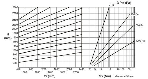
Required torque for Halton UTT-damper actuator
Operating principle
The Halton UTT dampers are used to shut off or control airflow in ductwork where tightness, thermal insulation and reliability are important.
In the closed position the Halton UTT damper leakage class is 3 in accordance with the EN1751 standard.
In the open position the blades are turned in the direction of flow and do not cause significant pressure losses.
Damper sizes conform with the international standards EN 1505, EN1506 and ISO 1707 for rectangular and circular ducts.
The maximum operation temperature of a standard damper is +100°C (for optional models +200°C).
Heat transmission of the damper is 6 W/(m 2 K).
Installation
Install the damper in the ductwork with the blades in horisontal or vertical position.
Fasten the damper in the ductwork using slip joints (SF=NA).
Optional models enable fastening the damper to duct flange by using bolts (SF=R2).
Drill holes in the damper flange if necessary (options SF=L1 / SF=L2).
Use a seal between the flanges in order to tighten the seam.
Fasten the models with circular connections by riveting or screwing.
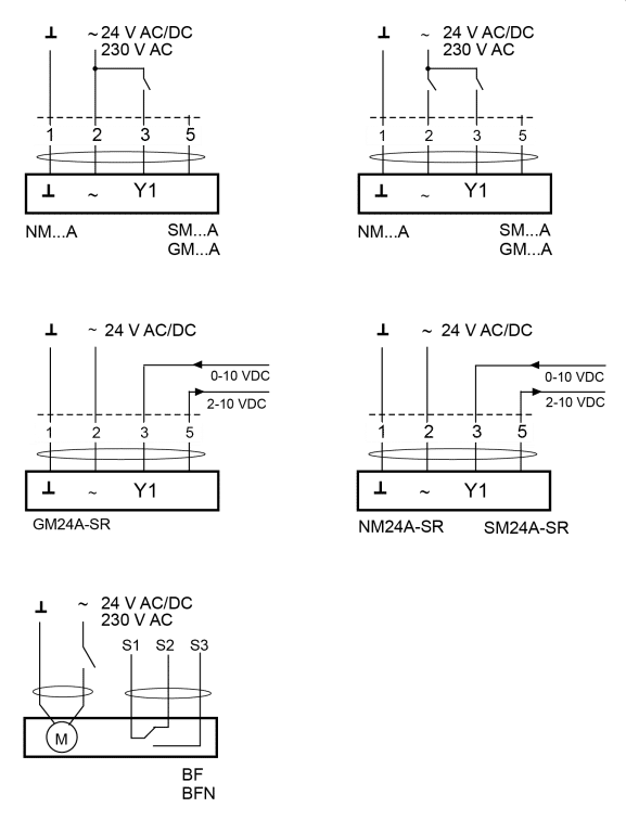
Wiring:
Specification
Function
Heat transmission of the damper does not exceed 6 W/(m2K).
The damper is suitable for either manual adjustment or actuator operation.
Materials
The casing and blades are made from galvanised steel or stainless steel (EN 1.4404/AISI 316L).
The blade gaskets are made of silicon (or EPDM- rubber).
The drive shaft socket is made of galvanised steel with self-lubricating slide bearings.
The bearing is made from an alloy of polyamide and molybdenum sulphide (or stainless steel AISI 316 or stainless steel AISI 304 or bronze).
Standards
The damper is installed into rectangular ducts in compliance with EN 1751, or in circular ducts D=100 …1250mm in accordance with EN 1751.
The damper meets the tightness requirements of EN 1751 class 3.
The casing of the damper meets the tightness requirements of EN 1751 class B.
Order code
UTT-S-W-H-D; CT-SF-MA-MD-BM-MO-AC-ZT
| Main options | |
| S = Type of duct connections | |
| R | Rectangular connections |
| C | Circular connections |
| W = Width [mm] | 100, +50, …, 2400 |
| H = Height [mm] | 100, +50, …, 2400 |
| D = Connection size for circular model [mm] | 100, 125, 160, 200, 250, 315, 400, 500, 630, 710, 800, 1000, 1250 |
| Other options and accessories | |
| CT = Type of circular connection | |
| D1 | 1 circular connection |
| D2 | 2 circular connections |
| SF = Flange option | |
| NA | Slip joints |
| L1 | Slip joints + flange connection |
| L2 | Flange connection, both sides |
| R2 | Flange connection, both sides with holes |
| P1 | Flange P30 |
| P2 | Flange P30 with FDL drilling |
| P3 | Flange connection with FDL drilling (Marine) |
| MA = Material | |
| CS | Steel |
| AS | Stainless steel (EN 1.4404/AISI 316L) |
| MD = Model | |
| N | Standard |
| H | Heat-proof |
| I | Insulated |
| J | Heat-proof and insulated |
| BM = Bearing material | |
| ST | Plastic |
| AS | Stainless steel (AISI 316) |
| SS | Stainless steel (AISI 304) |
| BR | Bronze (JN5) |
| MO = Actuator | |
| NA | Not assigned |
| MA | Manual handle |
| E1 | BF24 (no fuse), 24V, 18 Nm |
| E3 | BF230 (no fuse), 230V, 18 Nm |
| E7 | BF120 (no fuse), 120V, 18 Nm |
| M1 | BFN24-HL (no fuse), 24V, 9 Nm / 7 Nm |
| M2 | BFN230-HL (no fuse), 230V, 9 Nm / 7 Nm |
| P0 | Pneumatic, Rot.AT101 |
| A1 | SM24A (on-off), 24V, 20 Nm |
| A2 | SM24A-S (on-off), 24V, 20 Nm |
| A3 | SM230A (on-off), 230V, 20 Nm |
| A4 | SM230A-S (on-off), 230V, 20 Nm |
| A5 | SM24A-SR (modulating), 24V, 20 Nm |
| A6 | SF24A (on-off), 24V, 20 Nm |
| A7 | SF24A-S2 (on-off), 24V, 20 Nm |
| A8 | SFA (on-off), AC 24-240V/DC 24-125V, 20 Nm |
| A9 | SFA-S2 (on-off), AC 24-240V/DC 24-125V, 20 Nm |
| A0 | SF24A-SR (modulating), 24V, 20 Nm |
| A11 | SF24A-MP (modulating), 24V, 20 Nm |
| C1 | NM24A (on-off), 24V, 10 Nm |
| C2 | NM230A (on-off), 230V, 10 Nm |
| C3 | NM24A-SR (modulating), 24V, 10 Nm |
| M3 | SM24A-MA (modulating), 24V, 20 Nm |
| G1 | GM24A (on-off), 24V, 40 Nm |
| G2 | GM230A (on-off), 230V, 40 Nm |
| M4 | InMax-15-SF, VAC/DC 24…240 V, 15 Nm |
| M5 | NFA-S2, AC 24-240V/DC 24-125V, 10 Nm |
| K1 | FIC actuator |
| AC = Accessories | |
| BA | Bar adjustment |
| S4 | S2A Auxiliary switch |
| L1 | Limit switch, 1 pc (IP65) |
| L2 | Limit switch, 2 pcs (IP65) |
| AR | Position indication arrow |
| WH | Connector (Marine/Wieland) |
| WB | Connector (Marine/Wieland Blue1, MAC) |
| TG | Tag |
| ZT = Tailored product | |
| N | No |
| Y | Yes (ETO) |
Order code example
UTT-R-100-100-250; CT= D1, SF=NA, MA=CS, MD=N, BM=ST, MO=MA, AC=BA, ZT=N
Downloads
-
Halton UTT – Multi-blade airflow management damper (CAV)
Data
en
-
Halton UTT – Monisäleinen ilmavirran säätöpelti (CAV)
Data
fi
-
Halton UTT – Registre de réglage étanche à lames opposées (CAV)
Data
fr
-
Halton UTT – Luft- und wärmedichte Jalousieklappe
Data
de
-
Halton UTT – Jalusispjäll (CAV)
Data
se
-
Halton UTT – Fiche technique
Data
fr_FR
"*" indicates required fields
ABD – Automated Balancing Damper for kitchen ventilation (CE)
product
ABD – Automatic balancing damper for kitchen ventilation (ETL)
product
CID-01 – Zero leakage isolation damper
product
Halton BOX – Airflow management unit (VAV)
product
Halton Max MDC – Zone control damper for Halton Workplace system
product
Halton Max MLC – Airflow management damper (VAV)
product
Halton Max MOC – Airflow management damper (VAV)
product
Halton Max MOS – Airflow management damper (VAV)
product
Halton Max MSB – Slim airflow management damper (VAV)
product
Halton Max MUC – Ultrasound airflow management damper (VAV)
product

Halton PRA – Airflow management damper (CAV)
product
Halton PTS – Airflow management damper (single-blade)
product
Halton RMC – Airflow management damper (CAV)
product
Halton SA – Sound attenuator
product
Halton UKV – Airflow management damper (VAV)
product
Halton UTK – Multi-blade airflow management damper (CAV)
product
Halton UTT – Multi-blade airflow management damper (CAV)
product

Halton Vita VLR – Room airflow controller for Halton Vita Lab solutions
product
Halton Vita VLS – Fume cupboard controller for Halton Vita Lab solutions
product
KBD – Exhaust hood balancing damper (ETL)
product