Product / VLR
Halton Vita VLR – Room airflow controller for Halton Vita Lab solutions
The Halton Vita VLR airflow controller operates as a fundamental element of the supply and exhaust ductwork in the Halton Vita Lab solution.
This solution is an independent stand-alone system, which can be connected via bus communication to the BMS system.

Overview
The Halton Vita VLR controller operates as a fundamental element of the supply and exhaust ductwork in the Halton Vita Lab solution. This solution is an independent stand-alone system, which can be connected via bus communication to the BMS system.
Intended for all kind of environments, especially clean rooms or laboratory rooms. Airflow measuring is based on differential pressure between averaging cross measuring tubes.
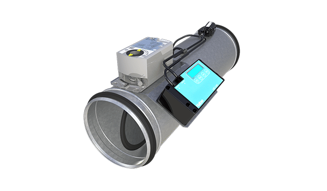
The room controller is equipped with a fast actuator and pressure differential sensor. It controls the room airflow or pressurisation so that the desired room balance or differential pressure between the room and the reference space is achieved.
Application
- Airflow is measured with cross measuring tubes or orifice plate
- Airflow control damper for Halton Vita Lab solution
- Circular and rectangular pressure-independent variable airflow controller
- Room supply and exhaust airflow installations
Key features
- Stand-alone system
- Pressure-independent operation
- Airflow rate and room pressure control modes are available
- Project specific settings are preset and tested at the factory
- Several connection sizes between 100-630 mm and 200×150 -800×400 mm
- Velocity range 1 — 6.5 m/s
- Can be connected to Buildings Management System (BMS)
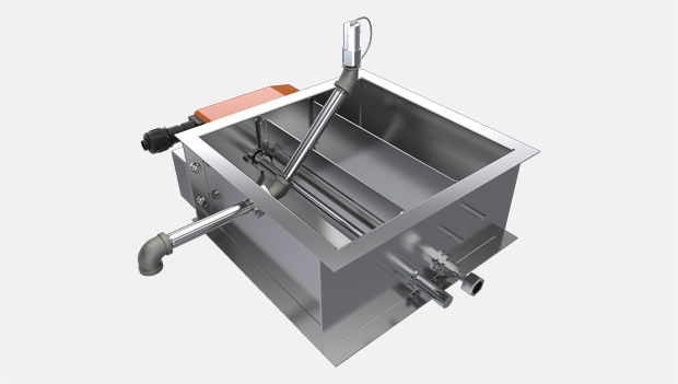
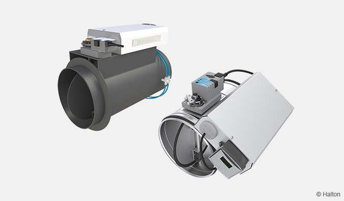
Operating principle
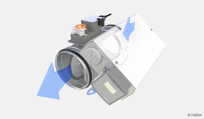
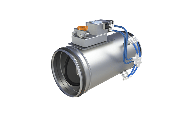
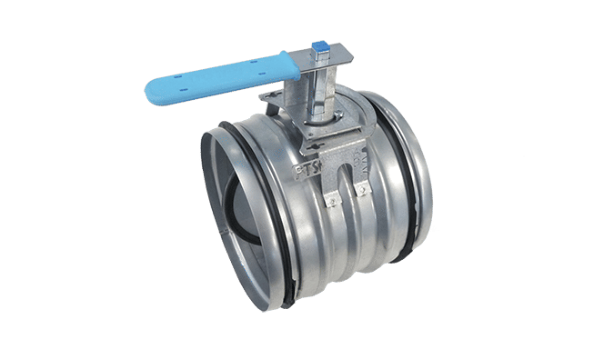
Fig.1. Operating principle of Halton Vita VLR with VFH damper
The airflow controller contains a cross-type airflow measurement probe, a VAV airflow controller, a fast actuator, differential pressure sensor and a blade (with or without gasket).
The airflow controller can function either as a supply or an exhaust unit. It maintains the required airflow through accurate measurement and airflow control, regardless of variations in the room conditions or duct pressure. The airflow measurement is based on a differential pressure generated by high-precision pickup tubes of the measurement probe. The tubes are engineered for sensitivity in low airflows and for low noise generation in high airflows.
Changes in room conditions can be adjusted manually from an end-user interface or by different sensors such as occupancy or room pressure sensors, thermostats or timers. The conditions can also be managed remotely from a building management system (BMS). The control signal and the airflow measurement data from the pickup tubes are processed in the Halton Vita VLR controller. The Halton Vita VLR controller gives the actuator a command to change the position of the damper blade, in order to keep the airflow at the predefined setpoint. The airflow setpoint can be modified between minimum and maximum settings from the room controller interface or a BMS.
Key technical data
| Feature | Value |
| Duct connection sizes | Circular: ø100-630 mm Rectangular: 200×150 – 800×400 mm |
| Material | Galvanised or stainless steel (EN 1.4404/AISI 316L) |
| Air velocity range |
|
| Operating range (ambient temperature) | 0-50 ℃ |
| Ambient relative humidity (non-condensing) | < 95% |
| Communication interface | ModBUS RTU/IP, BACnet/IP |
Operating modes
|
|
| Accessories |
|
| Protection class |
|
| Power supply |
|
| Standards and certifications
|
|
| Maintenance | According to the building maintenance program |
Features and options
| Category | Name | Description |
| Solution concept | Room airflow control | Suitable for spaces where the need for pressure control less rigorous. |
| Room pressure control | Suitable for spaces where safety requirements are exceptionally high. | |
| Total exhaust measurement | Used to control the pressure differences by measuring the total exhaust airflow rate from the Halton Vita VLZ controller | |
| Control concept | General supply, master | Room airflow compensation |
| General exhaust, master | Room airflow compensation | |
| General supply, slave | – | |
| General exhaust, slave | – | |
| Room pressure control, supply | Under pressure application | |
| Room pressure control, exhaust | Overpressure application | |
| Damper | VFH | Circular with gross tube, galvanised steel |
| VFC | Circular with orifice plate, galvanised steel | |
| VFA | Circular with orifice plate, antibacterial painted galvanised steel | |
| VFN | Circular with orifice plate, stainless steel (AISI 316L) | |
| VFI | Circular with cross tube, stainless steel (AISI 316L) | |
| VKR | Rectangular with gross tube, galvanised steel | |
| VLX | Rectangular with gross tube, galvanised steel, long or short model |
For more detailed information of the order code, see section Order code.
Solution description
Halton Vita VLR is a part of the Halton Vita Lab solution offering.
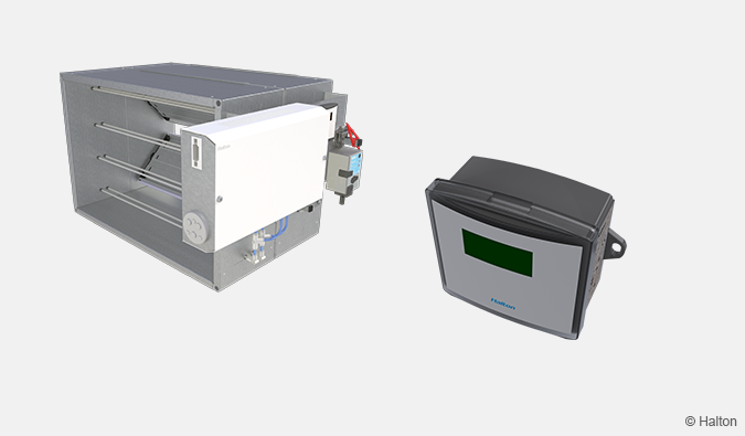
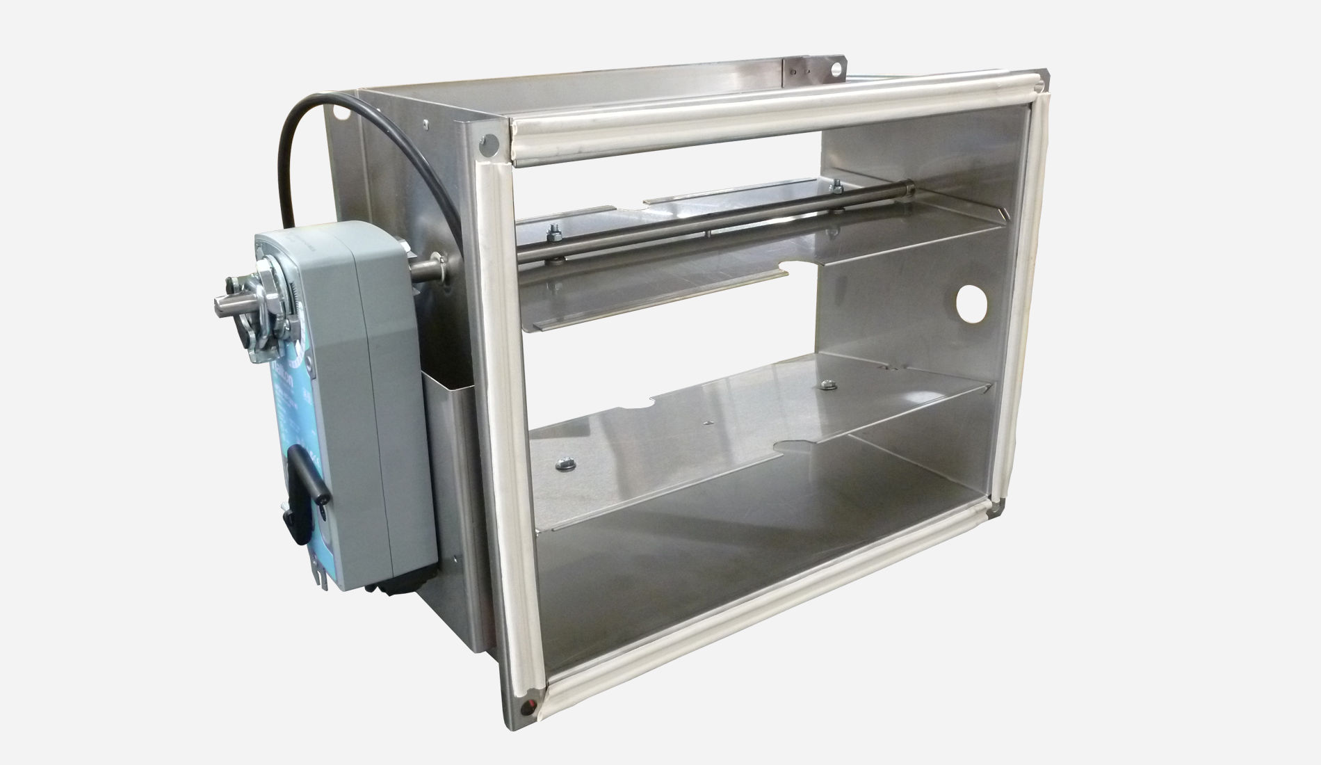
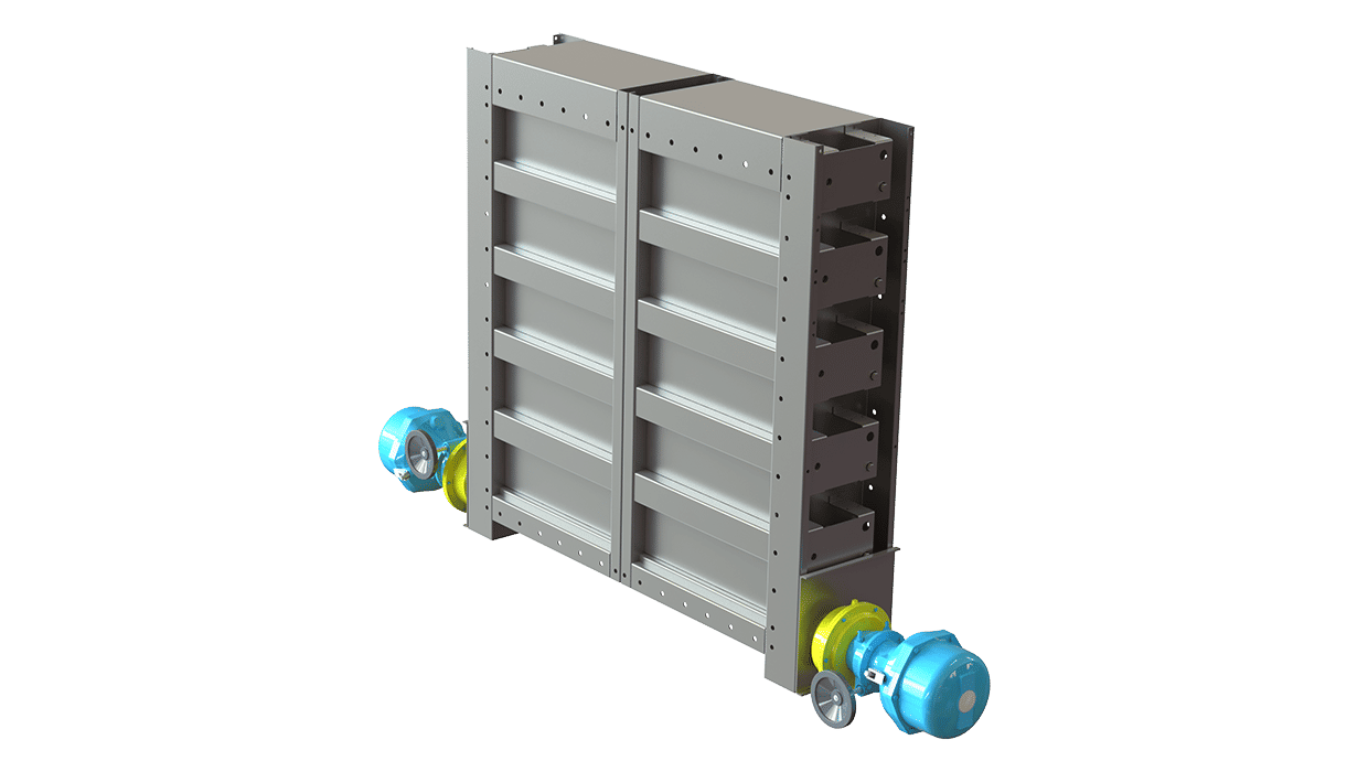
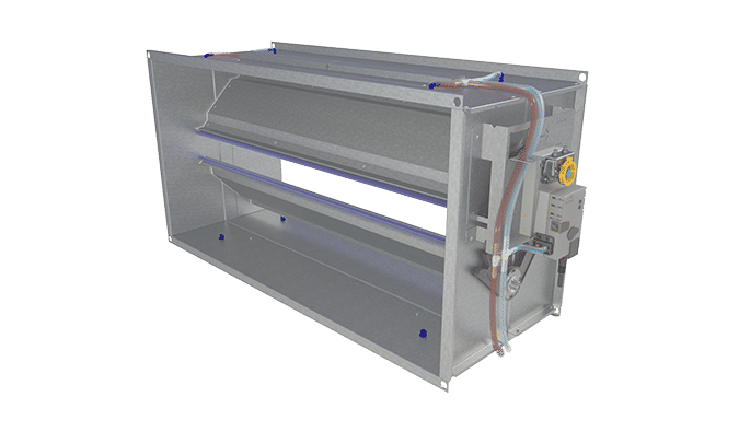
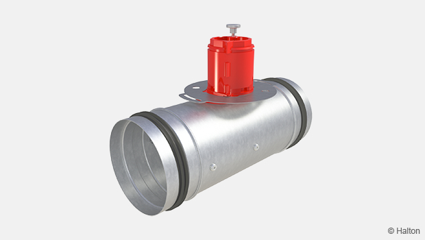
Fig.2. Halton Vita VLR + VKR damper combined with a Halton Vita Lab Room controller, Halton Vita VPT
Halton Vita VLR is a controller especially designed for controlling the automation system of laboratory and cleanroom environment. It is used for controlling the ventilation airflow, room temperature, and indoor air quality.
The automation package consists of a controller unit and optional components depending on customer needs: a wall panel and sensors for temperature, CO2, occupancy and pressure.
In the laboratory room Halton fume cupboard ventilation controllers Halton Vita VLS are connected to the Halton Vita VLR via internal BUS. The holistic system includes all components for high required laboratory ventilation control.
Application area
- Controlling the ventilation airflow, room pressure, room temperature, and indoor air quality in the laboratory and clean rooms
- The Halton Vita VLR controller is an important part of the Halton Vita Lab system, controlling room conditions when Halton Vita VLS controls fume cupboards
- Overall Halton Vita Lab system includes:
- Halton Vita Lab Room air conditioning applications:
- Supply airflow
- General exhaust
- Room pressure
- Temperature and CO2
- Halton Vita Lab Solo fume cupboard control
- Face velocity control
- Dual position airflow control
- Sash position control
- Sash movement control
- Double sensor control
- Halton Vita Lab Zone duct static pressure
- Zone pressure control
- Local exhaust units and all ventilated components in the laboratory environment
- Halton Vita Lab Room air conditioning applications:
Key features
- Factory-tested controller and wiring, easy to install
- Pre-installed project-specific parameters, quick to commission
- Several operating modes based on occupancy, thermal comfort, and indoor air quality
- Enables fully flexible layout solutions for changing needs in laboratory environment
- Highly energy-efficient and reliable system operation
Operating principle
Supply airflow control Halton Vita Lab Room is realized by
- racking the measured exhaust units; fume hoods and local exhausts
- setting the supply airflow setpoint to correspond the exhaust airflow rate
- applying a defined deviation between the exhaust and supply
Halton Vita Lab Room can also control
- the pressurization of the laboratory space based on the differential pressure measurement between the space and the ambient reference space
Halton Vita Lab Room –system can also maintain
- desired minimum air change in the room when exhaust airflow from exhaust units is insufficient
- room temperature either by general ventilation airflow rate control and/or by controlling the supply air temperature
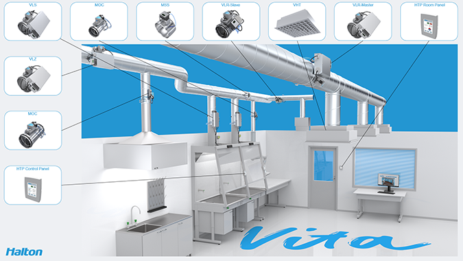
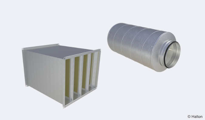
Fig.3. System components for Halton Vita Lab solutions.
Quick selection
Halton Vita VLR with VFH damper
| Size | qv | qv |
| min – max [l/s] | min – max [m3/h] | |
| 125 | 12 – 80 | 44 – 288 |
| 160 | 20 – 131 | 72 – 472 |
| 200 | 31 – 204 | 113 – 734 |
| 250 | 49 – 319 | 177 – 1148 |
| 315 | 78 – 507 | 281 – 1825 |
| 400 | 126 – 817 | 452 – 2941 |
| 500 | 296 – 1276 | 707 – 4594 |
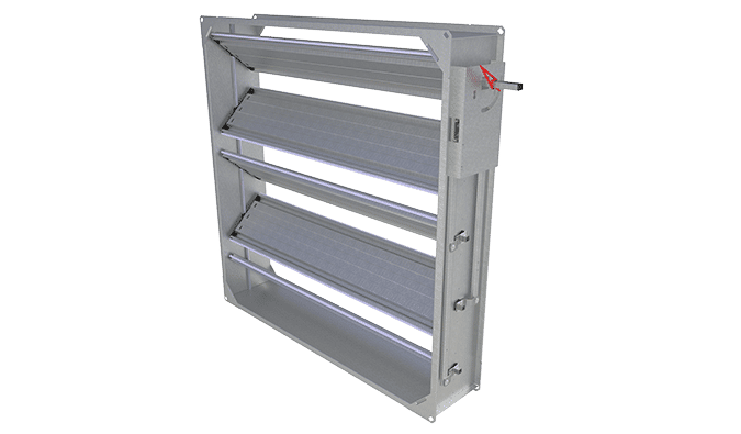
Structure and materials
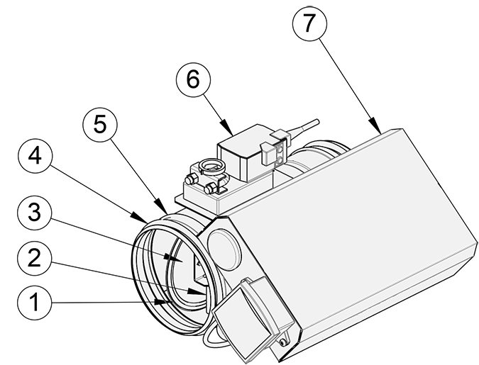
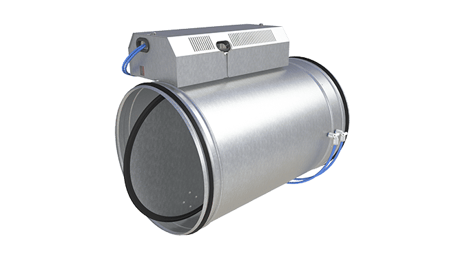
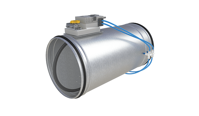
Fig.3. Halton Vita VLR with damper VFH
| No. | Part | Material | Note |
| 1 | Blade gasket | EPDM rybber | – |
| 2 | Shaft | Galvanised steel | Stainless steel (EN 14404/AISI316L) with damper option VFI |
| 3 | Blade | Galvanised steel | Stainless steel (EN 14404/AISI316L) with damper option VFI |
| 4 | Duct seal gasket | 1C-polyurethane hybrid | – |
| 5 | Casing | Galvanised steel | Stainless steel (EN 14404/AISI316L) with damper option VFI |
| 6 | Actuator | Plastic, steel, PVC cable | – |
| 7 | Airflow controller box | – | – |

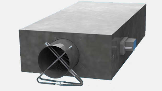
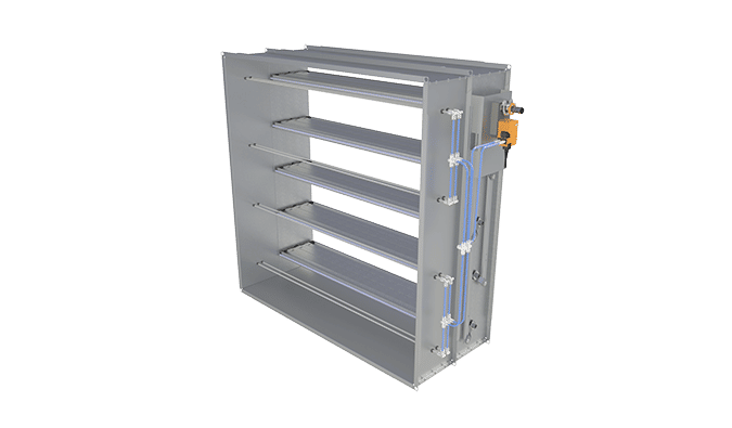
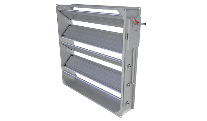
Fig. 4. Halton Vita VLR with damper VKR, insulated model
| No. | Part | Material |
| 1 | Casing | Galvanised steel |
| 2 | Measurement probe pipes | Aluminium |
| 3 | Blade bearing | Alloy of polyamide and molybdenum sphide (plastic) |
| 4 | Blandes | Galvanised steel. Sandwich design, inside polyurethane insulation (CFC free) |
| 5 | Blade gasket | Galvanised steel |
| 6 | Blade gaskets | Silicone |
| 7 | Measurement tubes | Polyurethane |
| 8 | Tube connection | Polyaceatal |
| 9 | External insulation | Galvanised steel casing. Insulation mineral wool |
| 10 | Transmitter enclosure | Polycarbonate (IP54) |
| 11 | Rectangular drive shaft | Galvanised steel (15×15 mm) |
| 12 | Operating model | Plastic, steel, PVC cable |
| 13 | Lever mechanism | Galvanised steel |
Dimensions and weight
Halton Vita VLR controller with airflow damper VFH, without insulation
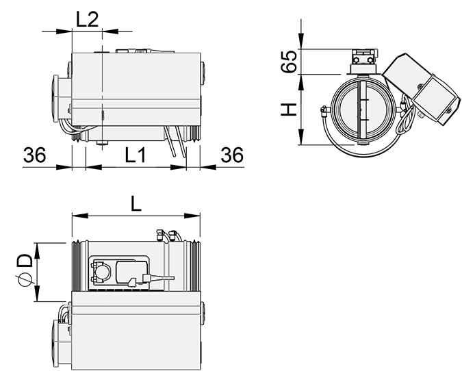
| NS [mm] |
⌀D [mm] |
L [mm] |
L1 [mm] |
L2 [mm] |
H [mm] |
Weight [kg] *) |
| 125 | 124 | 328 | 256 | 77 | 135 | 1.9 |
| 160 | 159 | 328 | 256 | 77 | 170 | 2.2 |
| 200 | 199 | 328 | 256 | 77 | 210 | 2.6 |
| 250 | 249 | 328 | 256 | 77 | 260 | 3.2 |
| 315 | 314 | 495 | 423 | 77 | 325 | 3.8 |
| 400 | 399 | 495 | 423 | 80 | 410 | 5.3 |
| 500 | 499 | 620 | 548 | 149 | 508 | 13.7 |
*) Without airflow controller box
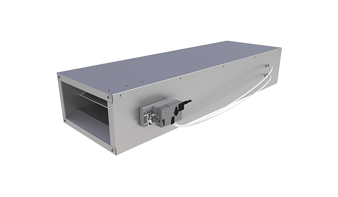
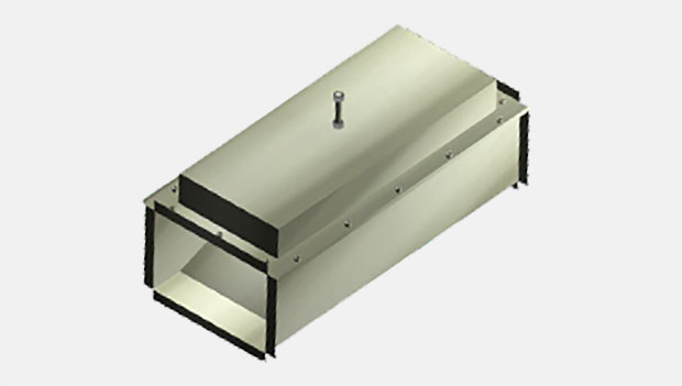
Halton Vita VLR with damper VKR, without insulation
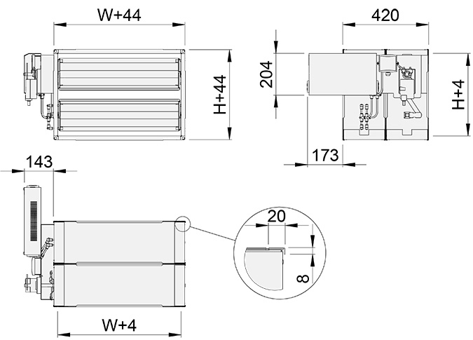
W = Duct connection width [mm]
200, 300, 400, 500, 600, 700, 800
H = Duct connection height [mm]
150, 200, 250, 300, 350, 400
Specification
Pressure-independent variable airflow control damper for supply and exhaust installations, fulfilling the following requirements:
Construction
- Airflow is adjusted by the position of the blade and measuring is based on differential pressure over the orifice plate
- Damper includes components
- Fast actuator, 2.5/4.0 s running time
- Controller box (“Master”) or junction box (“Slave”)
- Pressure transmitter
- Airflow measuring tubing
- Duct connection with integral airtight rubber gaskets
- Complete shut-off function (blade gasket), complies with EN 1751 class 4
- Casing tightness complies with EN 1751 class C
- Damper with external insulation include a 50mm mineral wool
Material
- VFH: Galvanised steel
- VFI: Stainless steel (AISI 316L)
Electrical data
Master
- Supply voltage: 230 VAC (230 VAC / 24 VAC -transformer included)
- Actuators / sensors supply voltage: 24 VAC
- Analog control: 2…10 VDC
- Analog measuring: 0…10 VDC (0-200 Pa)
- Modbus RTU, Modbus TCP, Bacnet IP -communication available via controller
Slave:
- Supply voltage 24 VAC
- Actuators / sensors supply voltage: 24 VAC
- Analog control: 2…10 VDC
- Analog measuring: 0…10 VDC (0-200 Pa)
- No bus communication
Parameter settings
Master
- Design parameters are calibrated at the factory. Halton service will verify all parameters during commissioning phase.
- Dampers are tested at the factory.
- Controller settings are adjustable with a PC- or a handheld tool
Installation
Wiring
The wiring must be carried out by professional technicians in accordance with local regulations. For the power supply, a safety-isolating transformer must be used.
Installation instructions and project-specific wiring diagrams are provided by Halton for all Halton Vita Lab Room system configurations.
For more information, see the Halton Vita Lab Room Design Guide available from Halton Sales.
Order code
VLR/S-C-T-D; L-H-M-IN-MA-FC-TF-CB-ZT
| Main options | |
| S = Solution concept | |
| A | Room airflow control |
| B | Room pressure control |
| C | Total exhaust measurement |
| C = Control concept | |
| 1S | General supply (slave) |
| 1E | General exhaust (slave) |
| 4S | General supply (master, Room airflow compensation) |
| 4E | General exhaust ( master, Room airflow compensation) |
| 5S | Room pressure control (supply, under pressure application) |
| 5E | Room pressure control (exhaust, overpressure application) |
| T = Damper/measurement unit type | |
| A | VFH (galvanised steel, cross tube) |
| B | VFC (galvanised steel, orifice) |
| C | VFA (galvanised steel, orifice, antibacterial) |
| D | VFN (stainless steel, orifice) |
| E | VFI (stainless steel, cross tube) |
| K | VKR (rectangular, galvanised steel, cross tube) |
| L | VLX/L (galvanised steel, cross tube, long version) |
| M | VLX/S (galvanised steel, cross tube, short version) |
| D = Duct connection size [mm] | 0, 100, 125, 160, 200, 250, 315, 400, 500 |
| Other options and accessories | |
| L = Duct connection length [mm] | 0, 200, 300, 400, 500, 600, 700, 800 |
| H =Duct connection height [mm] | 0, 150, 200, 250, 300, 350, 400 |
| M = Model | |
| S | Supply |
| E | Exhaust |
| IN = Insulation | |
| NA | Not assigned |
| I1 | Insulated, 25 mm |
| I2 | Insulated, 40 mm |
| I3 | Insulated, 50 mm |
| MA = Material | |
| CS | Hot-galvanised steel |
| AS | Stainless steel (AISI 316) |
| FC = Controller | |
| A1 | VLC-A1 (Modbus, 2 port, 15 I/O) |
| A2 | VLC-A2 (Modbus, 3 port, 28 I/O) |
| TF = Transformer | |
| N | No |
| TF1 | 230/24 transformer (35VA) |
| TF2 | 230/24 transformer (60VA) |
| CB = Control box | |
| CB1 | Galvanised box, delivered attached to damper/measurement unit |
| CB2 | Galvanised box, delivered separately from damper/measurement unit |
| ZT = Tailored product | |
| N | No |
| Y | Yes (ETO) |
| Sub products and accessories (ordered separately) |
|
| Halton Vita HTP | Control panel |
Order code example
VLR/A-B-200; L=NA, H=NA, M=S, FC=A1, TF=TF1, CB=CB1, ZT=N
Downloads
-
Halton Vita Laboratory Solutions
Data
DK -
Halton Vita Solutions Laboratoires
Data
Français (fr) -
Halton Vita Lab Room – Suunnitteluopas
Data
Suomi (fi) -
Halton Vita Lab Room – Design Guide
Data
English (en) -
Halton Vita Laboratorio-ratkaisut
Data
Suomi (fi) -
Halton Vita Laboratory Solutions
Data
English (en) -
Halton Vita lösningar för laboratorier
Data
Svenska (sv)
"*" indicates required fields
ABD – Automated Balancing Damper for kitchen ventilation (CE)
product
ABD – Automatic balancing damper for kitchen ventilation (ETL)
product
CID-01 – Zero leakage isolation damper
product
Halton BOX – Airflow management unit (VAV)
product
Halton Max MDC – Zone control damper for Halton Workplace system
product
Halton Max MLC – Airflow management damper (VAV)
product
Halton Max MOC – Airflow management damper (VAV)
product
Halton Max MOS – Airflow management damper (VAV)
product
Halton Max MSB – Slim airflow management damper (VAV)
product
Halton Max MUC – Ultrasound airflow management damper (VAV)
product

Halton PRA – Airflow management damper (CAV)
product
Halton PTS – Airflow management damper (single-blade)
product
Halton RMC – Airflow management damper (CAV)
product
Halton SA – Sound attenuator
product
Halton UKV – Airflow management damper (VAV)
product
Halton UTK – Multi-blade airflow management damper (CAV)
product
Halton UTT – Multi-blade airflow management damper (CAV)
product
Halton Vita VLR – Room airflow controller for Halton Vita Lab solutions
product
Halton Vita VLS – Fume cupboard controller for Halton Vita Lab solutions
product
KBD – Exhaust hood balancing damper (ETL)
product