Product / PTS
Overview
- Shut-off, adjustment, balancing or control damper
- Casing leakage classification: EN 1751, Class C
- Casing and damper blade made of galvanized steel
- Tightness classification of shut-off damper: EN 1751, Class 4 (PTS/A model)
Product models and accessories
- Shut-off, adjustment, balancing or control damper
- Adjustment, balancing or control damper
- Adjustment, balancing or control damper with perforated blade
- Several actuator options
Quick selection

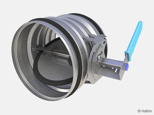
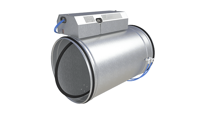
Fig.1. Halton PTS with blade gasket (A)
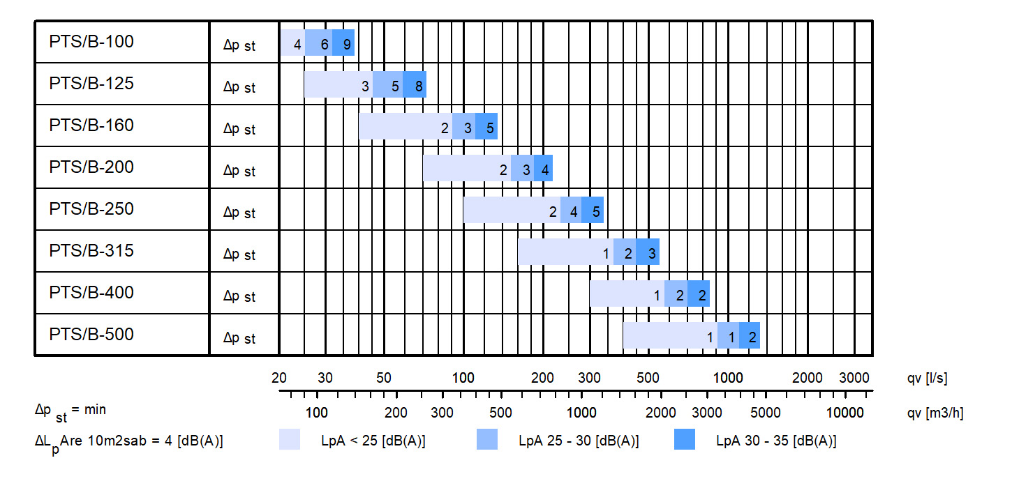
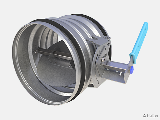
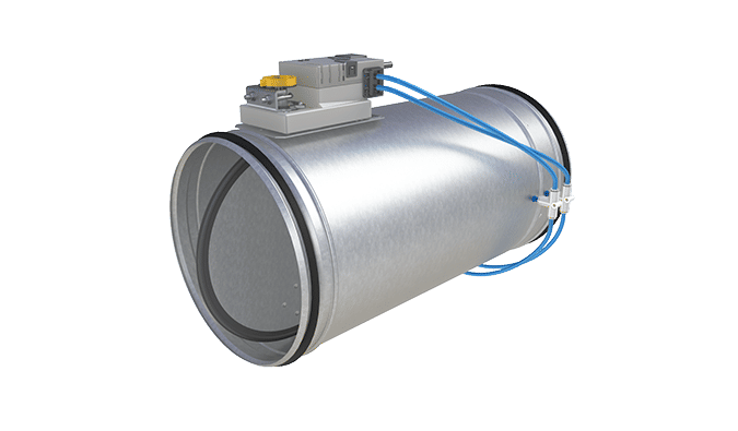
Fig.2. Halton PTS without blade gasket (B)
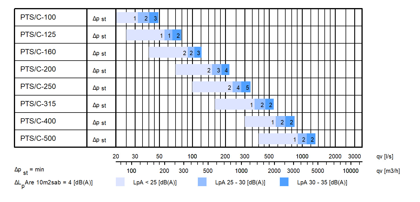
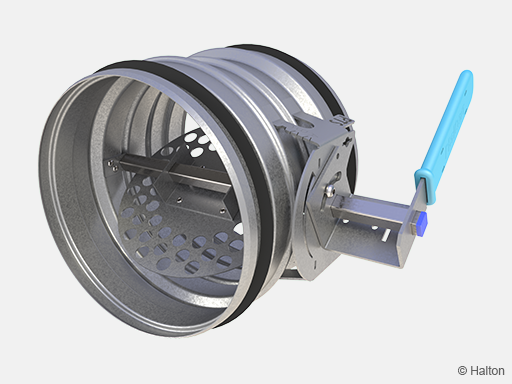
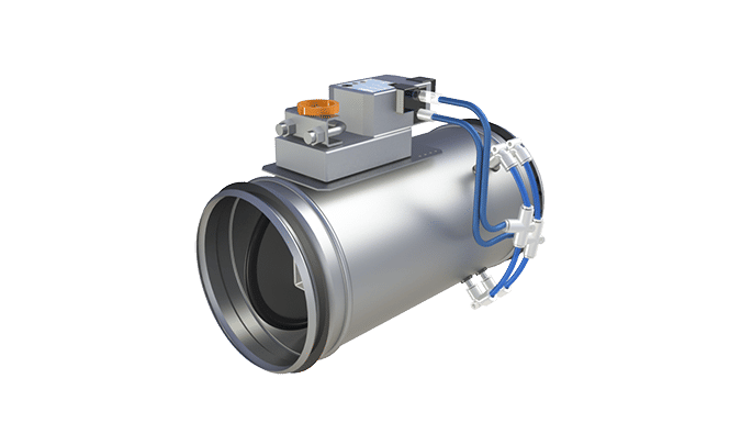
Fig.3. Halton PTS perforated blade (C)
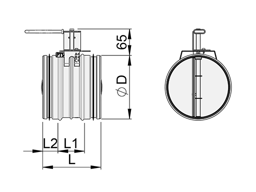
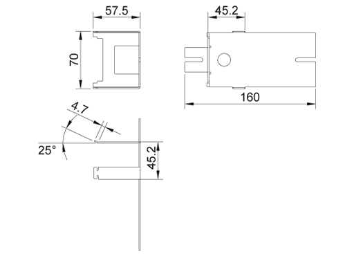
Dimensions and weight
| NS [mm] |
L [mm] |
L1 [mm] |
L2 [mm] |
ØD [mm] |
| 100 | 145 | 70 | 36 | 99 |
| 125 | 145 | 70 | 36 | 124 |
| 160 | 145 | 70 | 36 | 159 |
| 200 | 145 | 70 | 36 | 199 |
| 250 | 145 | 70 | 36 | 249 |
| 315 | 145 | 70 | 36 | 314 |
| 400 | 245 | 175 | 35 | 399 |
| 500 | 245 | 175 | 35 | 499 |
Actuator platform, low (ML)
Actuator platform, high (MH)
Weight [kg]
| NS | PTS/A | PTS/B | PTS/C |
| 100 | 0.5 | 0.5 | 0.5 |
| 125 | 0.6 | 0.6 | 0.6 |
| 160 | 0.8 | 0.7 | 0.7 |
| 200 | 1.1 | 0.9 | 0.8 |
| 250 | 1.5 | 1.1 | 1.1 |
| 315 | 2.1 | 1.5 | 1.4 |
| 400 | 3.3 | 2.4 | |
| 500 | 4.9 | 3.6 |
Material
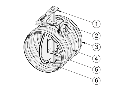
| No. | Part | Material | Note |
| 1 | Operating mechanism |
Galvanised steel | – |
| 2 | Actuator platform | Galvanised steel | – |
| 3 | Duct gaskets | 1C-polyurethane hybrid | – |
| 4 | Casing | Galvanised steel | – |
| 5 | Blade and shaft | Galvanised steel | – |
| 6 | Blade gasket | EPDM rubber | Used only in PTS/A model |
Product models
There are three different product models, for different purposes:
- Shut-off, adjustment, balancing or control damper, PTS/A. Tightness classification: EN 1751, Class 4
- Adjustment, balancing or control damper, PTS/B
- Adjustment, balancing or control damper with perforated blade, PTS/C
Minimum torque
| Model and size [mm] | 4 Nm | 10 Nm |
| PTS/A 100…250 | x | |
| PTS/A 315…500 | x | |
| PTS/B 100…500 | x | |
| PTS/C 100…500 | x |
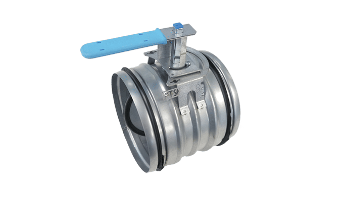
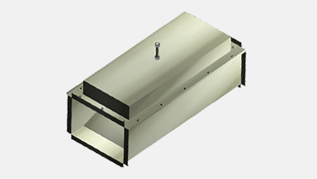
Manual operation
Handle for manual operation with blade position locking.
Actuator options
Standard actuators:
| Code | Name | Manufac. | Torque Nm |
Power supply |
Control type |
Power consuption |
| B1 | LM24A | Belimo | 5 | 24 VAC/VDC | On-off, 2-wire | 3 VA/2 W |
| B2 | LM230A | Belimo | 5 | 230 VAC | On-off, 2-wire | 12 VA/1 W |
| B3 | LM24A-SR | Belimo | 5 | 24 VAC/VDC | Modulating 0…10 VDC |
4 VA/2 W |
| B4 | NM24A | Belimo | 10 | 24 VAC/VDC | On-off, 2-wire | 3.5 VA/2 W |
| B5 | NM230A | Belimo | 10 | 230 VAC | On-off, 2-wire | 18 VA/2 W |
| B6 | NM24A-SR | Belimo | 10 | 24 VAC | Modulating 0…10 VDC |
3 VA/1.5 W |
| B7 | LF24 | Belimo | 4 | 24 VAC | On-off, spring return | 7 VA/5 W |
| B8 | LF230 | Belimo | 4 | 230 VAC | On-off, spring return | 7 VA/5 W |
| X1 | GDB111.1E/KN | Siemens | 5 | 24 VAC | KNX bus | 1 VA/0.5 W |
| X2 | GLB111.1E/KN | Siemens | 10 | 24 VAC | KNX bus | 3 VA/2.5 W |
| X3 | GDB161.1E | Siemens | 5 | AC/DC 24 V | Modulating | 2.1 VA/1.2W |
| X4 | GLB161.1E | Siemens | 10 | AC/DC 24 V | Modulating | 2.5 VA/1.5W |
| X5 | GDB141.1E | Siemens | 5 | AC/DC 24 V | 2/3 position | 2.5 VA/1.1W |
| X6 | GLB141.1E | Siemens | 10 | AC/DC 24 V | 2/3 position | 2.0 VA/1.3W |
| V5 | LM24A-VST | Belimo | 5 | AC/DC 24 V | Control communicative PP | 2 VA/1 W |
| V6 | NM24A-VST | Belimo | 10 | AC/DC 24 V | Control communicative PP | 4 VA/2 W |
| M1 | BFN24 (Marine) | Belimo | 9/7 | AC/DC 24 V | On-off, spring return | 6 VA/4 W |
| M2 | BFN230 (Marine) | Belimo | 9/7 | 230 VAC | On-off, spring return | 9 VA/4.5 W |
| M3 | SM24A-MA-C7 (Marine) | Belimo | 20 | AC/DC 24 V | Modulating 4…20 mA |
6 VA/3.5 W |
| M4 | InMax-15-SF (Marine) | Schischek | 15/30 | 24…240 VAC/DC | On-off, spring return, 3-point | – |
If other actuator types are required, consult Halton in order to specify the type and manufacturer.
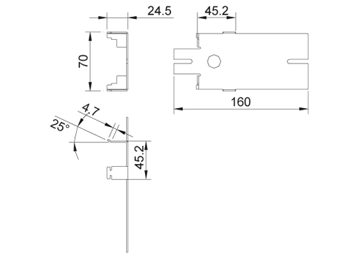
After sales installation of the actuator
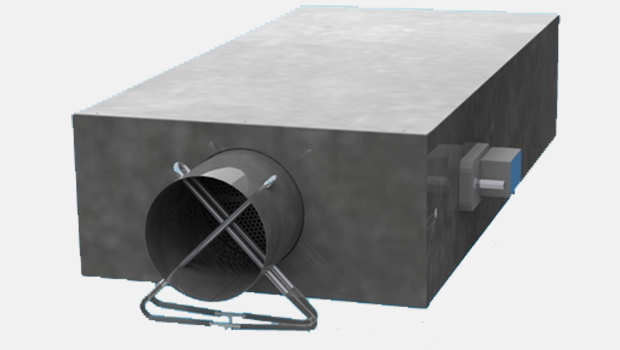
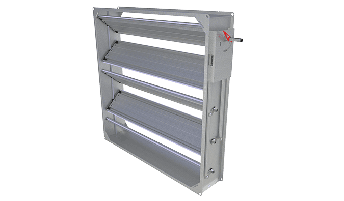
Actuator installation on the site is possible with the help of an actuator bed and extension shaft. This enables installation of a universal actuator type. The actuator bed selected can be of standard type when the ductwork is not insulated or of high type if the ductwork is insulated.
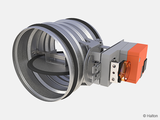
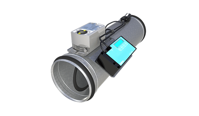
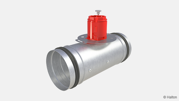
Fig.1. Halton PTS/A with actuator (B4 = NM24A)
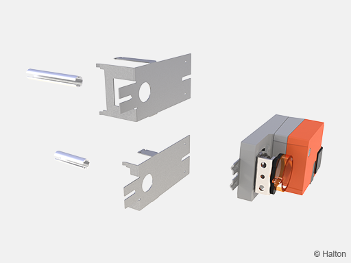
Fig.2. Actuator with installation kit low (IL) and high (IH)
Function
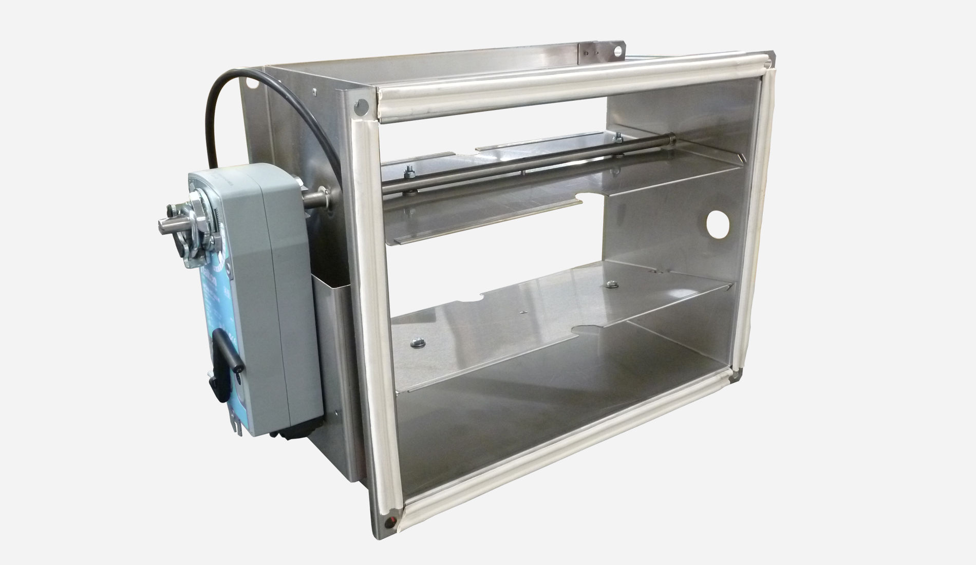
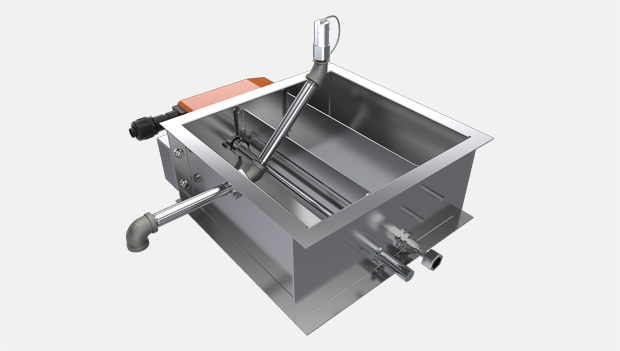
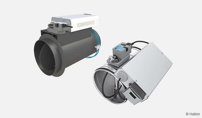
The Halton PTS unit can operate as a shut-off, control or adjustment damper depending on the product model. This damper is available for circular standard duct sizes 100 mm to 500 mm. Damper position is visually indicated below the operating mechanism.
The Halton PTS/A is a shut-off damper of leakage class 4 according to the EN 1751 standard. It includes rubber gaskets to ensure low leakage flow when the damper is in closed position. The PTS/A is available with a handle for manual operation or with an electric actuator for on-off control or for modulating control using a 0…10 VDC control signal.
The Halton PTS/B can be used for airflow control or adjustment of airflow rates in the ductwork. It includes a steel blade without gasket. The PTS/B is available with a handle for manual operation or with an electric actuator for on-off control or for modulating control using a 0…10 VDC control signal.
The Halton PTS/C is an airflow adjustment damper. The damper blade is a perforated blade that is acoustically and operationally designed for balancing of airflow rates.
The electric actuator is normally installed in the factory on the actuator platform with screws. On-site actuator installation is possible with the help of an actuator installation kit. The actuator installation kit, available as an accessory, includes an actuator platform and extension shaft for universal actuator fixing. The actuator platform and actuator can be installed easily using standard hand tools.
Halton PTS/A
Halton PTS/B
Halton PTS/C
Installation
Fasten the damper to the ductwork with, e.g., rivets. Ensure that the rivets do not prevent the operation of the damper. The position of each rivet must be at least 10 mm from the duct end.
External duct gaskets ensure an airtight joint when the damper has been mechanically fastened to the duct with rivets or screws.
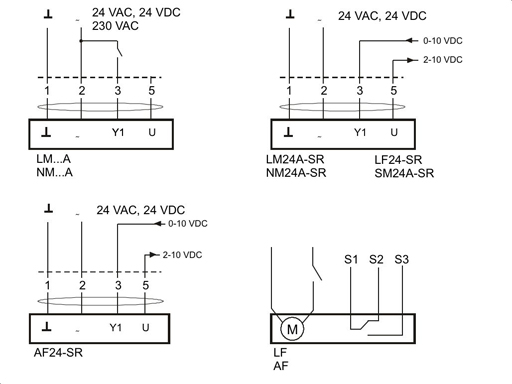
The electric actuator (where applicable) is to be connected to the power supply and control signal wires according to the wiring diagram. Examples of connections for the standard actuators are shown in a separate diagram.
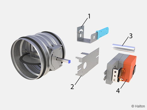
The electric actuator can also be installed, when necessary, in an on-site procedure with the help of an actuator platform and universal shaft fitting, available as an accessory:
Remove the operating mechanism (1) by opening the locking screw.
Assemble the actuator platform in the location of the operation mechanism (2) and ensure its stability mechanically by bending the legs of the actuator platform with a hand tool.
The universal actuator fitting enables connection of most actuator types to the shaft (3) (4).
Wire connections are to be performed according to the instruction for the actuator installed.
Electric wire connections
Belimo
Specification
The casing and circular (perforated) blade of the shut-off / adjustment / control damper shall be made of galvanised steel.
The shut-off damper shall meet EN 1751, Class 4 tightness requirements.
External rubber gaskets on the spigot shall provide an airtight connection to circular ductwork.
Order code
PTS-S-D; MA-MO-AC-ZT
S = Model
A Damper with blade gasket
B Damper without blade gasket
C Damper with perforated blade
D = Duct connection size [mm]
100, 125, 160, 200, 250, 315, 400, 500
Other options and accessories
MA = Material
CS Steel
MO = Actuator type
MA Manual handle
B1 LM24A, 24 VAC/VDC (on-off), 5 Nm
B2 LM230A, 230 VAC (on-off), 5 Nm
B3 LM24A-SR, 24 VAC/VDC (modulating), 5 Nm
B4 NM24A, 24 VAC/VDC (on-off), 10 Nm
B5 NM230A, 230 VAC (on-off), 10 Nm
B6 NM24A-SR, 24 VAC/VDC (modulating), 10 Nm
B7 LF24, 24 VAC/VDC (on-off, spring return), 4 Nm
B8 LF230, 230 VAC (on-off, spring return), 4 Nm
X1 GDB111.1E/KN (KNX bus), 5 Nm
X2 GLB111.1E/KN (KNX bus), 10 Nm
X3 GDB161.1E AC/DC 24 V, (modulating), 5 Nm
X4 GLB161.1E AC/DC 24 V, (modulating), 10 Nm
X5 GDB141.1E AC/DC 24 V, (2/3 position), 5 Nm
X6 GLB141.1E AC/DC 24 V, (2/3 position), 10 Nm
V5 LM24A-VST, (DC 0/2…10 V), 5 Nm
V6 NM24A-VST, (DC 0/2…10 V), 10Nm
M1 BFN24 (Marine)
M2 BFN230 (Marine)
M3 SM24A-MA-C7 (Marine)
M4 InMax-15-SF (Marine)
NA Not assigned
AC = Accessories
BA Bar adjustment
ML Actuator platform, low
MH Actuator platform, high
IL Installation kit for actuator, low
IH Installation kit for actuator, high
IJ Actuator platform (for LF actuator)
WB Connector (Marine/Wieland Blue1, MAC)
WM Connector (Marine/Wieland Blue2, MAC)
ZT = Tailored product
N No
Y Yes (ETO)
Order code example
PTS-A-160; MA=CS, MO=B1, AC=ML, ZT=N
Downloads
-
Halton PTS – Airflow management damper (single-blade)
Data
en
-
Halton PTS – Ilmavirran säätöpelti (yksiläppäinen)
Data
fi
-
Halton PTS – Registre de réglage étanche
Data
fr
-
Halton PTS – Drosselklappe
Data
de
-
Halton PTS – Spjäll (enbladig)
Data
se
-
浩盾PTS-C圆形单叶调节阀
Data
cn
-
Halton PTS – Fiche technique
Data
fr_FR
"*" indicates required fields
ABD – Automated Balancing Damper for kitchen ventilation (CE)
product
ABD – Automatic balancing damper for kitchen ventilation (ETL)
product
CID-01 – Zero leakage isolation damper
product
Halton BOX – Airflow management unit (VAV)
product
Halton Max MDC – Zone control damper for Halton Workplace system
product
Halton Max MLC – Airflow management damper (VAV)
product
Halton Max MOC – Airflow management damper (VAV)
product
Halton Max MOS – Airflow management damper (VAV)
product
Halton Max MSB – Slim airflow management damper (VAV)
product
Halton Max MUC – Ultrasound airflow management damper (VAV)
product

Halton PRA – Airflow management damper (CAV)
product
Halton PTS – Airflow management damper (single-blade)
product
Halton RMC – Airflow management damper (CAV)
product
Halton SA – Sound attenuator
product
Halton UKV – Airflow management damper (VAV)
product
Halton UTK – Multi-blade airflow management damper (CAV)
product
Halton UTT – Multi-blade airflow management damper (CAV)
product

Halton Vita VLR – Room airflow controller for Halton Vita Lab solutions
product
Halton Vita VLS – Fume cupboard controller for Halton Vita Lab solutions
product
KBD – Exhaust hood balancing damper (ETL)
product