Product / UKV
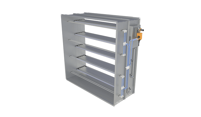
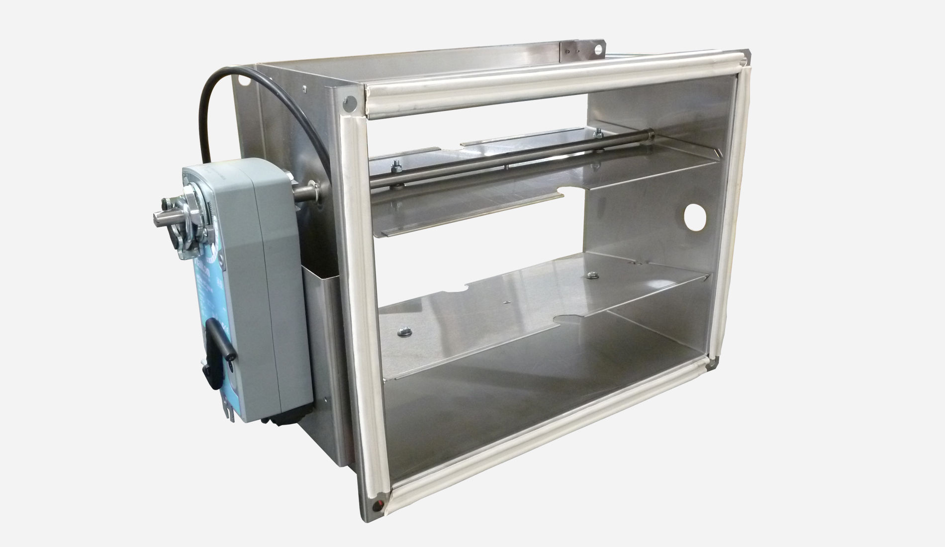
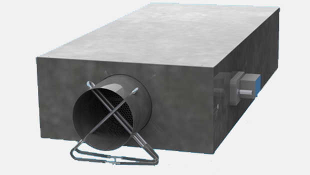
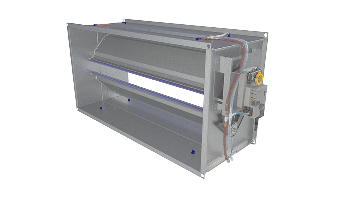
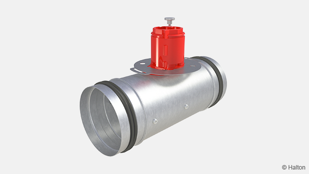
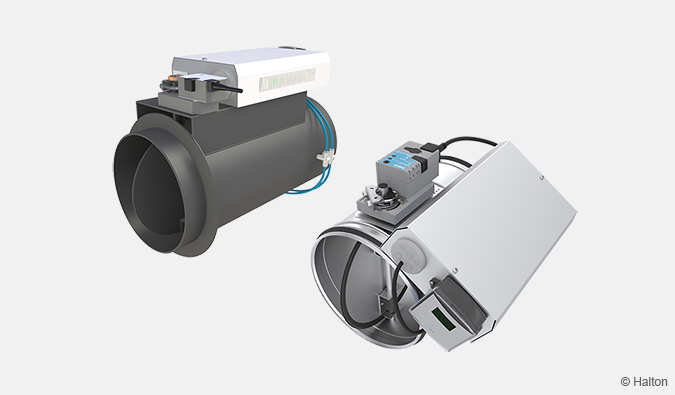
Halton UKV – Airflow management damper (VAV)
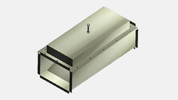
Rectangular VAV and CAV with factory-set airflow range limits option (min./max. airflow rates). Used for different airflow and duct pressure control applications. Pressure-independent operation. Available in various rectangular modular sizes.
- Suitable for large airflow rates, from 1 m/s up-to 11 m/s on some models
- Several airflow controller options
Overview
- Control damper for different airflow and duct pressure control applications
- Model with shut-off operation; tightness fulfils EN 1751, class 1 requirements
- Casing tightness fulfils EN 1751, class B requirements
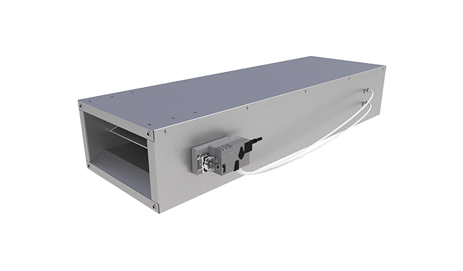
- Two extra models with external insulation 15 mm and 30 mm
- Several airflow controller options
- Factory-set airflow range limits (min./max. airflow rates) as an option
- Pressure-independent operation
- Galvanised steel design
- Suitable for large air flow rates, from 1 m/s up-to 11 m/s on some models
Dimensions
Without insulation
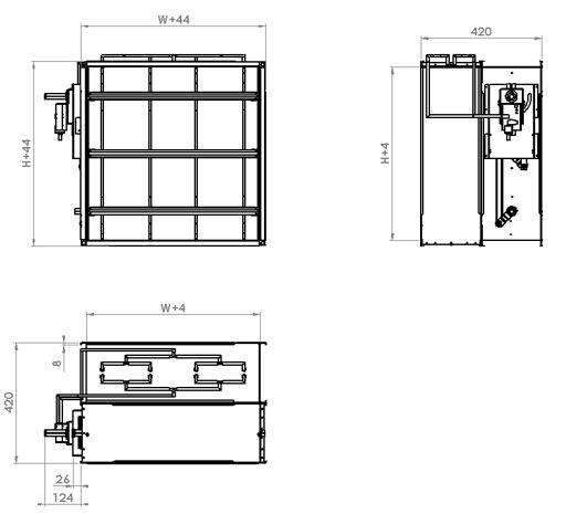
W = Width (Diameter of duct connection)
200, 250, 300 … 1550, 1600, with increment of 50 mm
H = Height (Diameter of duct connection)
200, 250, 300 … 950, 1000, with increment of 50 mm
With 15 mm insulation
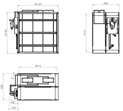
W = Width, Diameter of duct connection
200, 250, 300 … 1550, 1600, with increment of 50 mm
H = Height, Diameter of duct connection
200, 250, 300 … 950, 1000, with increment of 50 mm
With 30 mm insulation
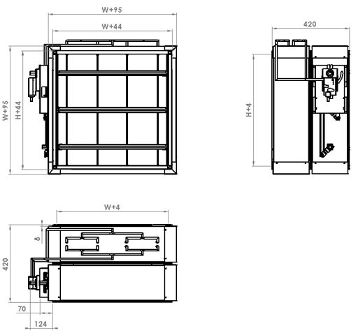
W = Width, Diameter of duct connection
200, 250, 300 … 1550, 1600, with increment of 50 mm
H = Height, Diameter of duct connection
200, 250, 300 … 950, 1000, with increment of 50 mm
Material
| Part | Material | Note |
| Casing | Galvanised steel | – |
| Blades | Galvanised steel | Sandwich design |
| Damper blade insulation | Polyurethane | When width > 1 300 mm |
| Damper blade gaskets | Silicon | – |
| Slide bearings | Alloy of polyamide and molybdenum suphide |
– |
| Measurement probe | Aluminium | – |
| External insulation | Mineral wool | – |
| Rectangular drive shaft | Galvanised steel | 15x15mm |
Function
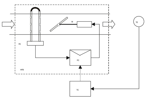
The Halton UKV is a variable air volume control damper for ventilation systems. The damper can function electrically, with maximum and minimum set values for volume flow rate, factory preset. The damper can also be used as constant air volume control damper. The damper maintains an airflow rate in a duct branch in accordance with the set value independent of duct upstream pressure variation. The set value can be achieved by room temperature controller with output (0…10VDC or 2…10VDC) which will reset the airflow rate for the required value.
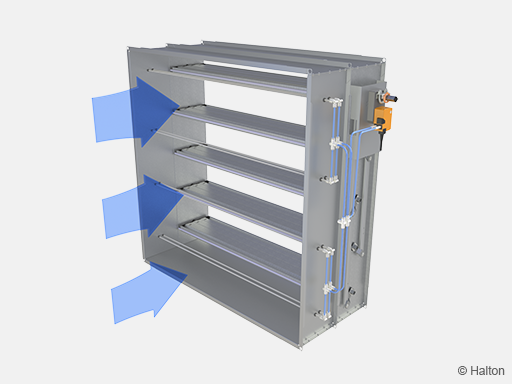
Variation of upstream pressure will affect the measurement system; it will notice a difference between the set point and measured value. Volume controller will send a signal to the actuator to recover the set value.
The dampers can be connected to a building management system, whereupon they can be remotely controlled. In such a case, the volume flow rates in different spaces of the building can also be monitored.
The Halton UKV meets the requirements of EN 1751 tightness class 1
Product models
The Halton UKV airflow control damper is available in several versions.
| Model | Description |
| UKV, MD=N | No external frame insulation |
| UKV, MD=I1 | With 15 mm external insulation |
| UKV, MD=I2 | With 30 mm external insulation |
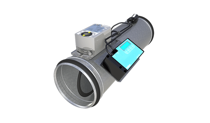
Control units (CU)
The Halton UKV airflow control damper can be equipped with several different control units for either airflow or duct pressure control.
Airflow controller options:
| Controller | Notes | Torque [Nm] |
Damper size [mm] |
Commication interface | Order code (link to datasheet) |
| EM | Analogue controller Manufacturer: Belimo |
5 | 100-250 | DC0..10V/2..10V | EM = LMV-D3-MF-F.1 HI (DC 0/2…10 V), 5 Nm |
| EK | Analogue controller Manufacturer: Belimo |
10 | 100-250 | DC0..10V/2..10V | EK = NMV-D3-MF-F.1 HI (DC 0/2…10 V), 10 Nm |
| EC | Controller with NFC connectivity for mobile onsite parameter adjustment (Belimo Assistant App). Analogue or MPbus. Manufacturer: Belimo |
5 | 100-250 | Belimo MP bus or 0..10V/2..10V |
EC = LMV-D3-MP (MP bus), 5 Nm |
| EE | Controller with NFC connectivity for mobile onsite parameter adjustment (Belimo Assistant App). Analogue or MPbus. Manufacturer: Belimo |
10 | 100-630 | Belimo MP bus or 0..10V/2..10V |
EE = NMV-D3-MP (MP bus), 10 Nm |
| ER | Controller with KNX Manufacturer: Belimo |
5 | 100-250 | KNX | ER = LMV-D3-KNX (KNX bus), 5 Nm |
| ES | Controller with KNX Manufacturer: Belimo |
10 | 100-630 | KNX | ES = NMV-D3-KNX (KNX bus), 10 Nm |
| ET | Controller with Modbus Manufacturer: Belimo |
5 | 100-250 | Modbus | ET = LMV-D3-MOD (Modbus RTU), 5 Nm |
| EU | Controller with Modbus Manufacturer: Belimo |
10 | 100-630 | Modbus | EU = NMV-D3-MOD (Modbus RTU), 10 Nm |
| EH | Analogue controller Manufacturer: Siemens |
5 | 100-250 | DC0..10V/ 2..10V | EH = GDB181.1E/3 (DC 0/2…10V), 5 Nm |
| EG | Analogue controller Manufacturer: Siemens |
10 | 100-630 | DC0..10V/2..10V | EG = GLB181.1E/3 (DC 0/2…10V), 10 Nm |
| EV | Controller with KNX Manufacturer: Siemens |
5 | 100-250 | KNX | EV = GDB181.1E/KN (KNX bus), 5 Nm |
| EW | Actuator with KNX Manufacturer: Siemens |
10 | 100-630 | KNX | EW = GLB181.1E/KN (KNX bus), 10 Nm |
| EB | Actuator with Modbus RTU (RS-485) Manufacturer: Siemens |
5 | 100-250 | Modbus | EB = GDB181.1E/MO (Modbus RTU), 5 Nm |
| EF | Actuator with Modbus RTU (RS-485) Manufacturer: Siemens |
10 | 100-630 | Modbus | EF = GLB181.1E/MO (Modbus RTU), 10 Nm |
| V1 | Analogue controller Manufacturer: Belimo |
5 | 100-250 | DC0..10V/2..10V | V1 = LM24A-VST, (DC 0/2…10 V), 5 Nm + VRU-D3-BAC |
| V2 | Analogue controller Manufacturer: Belimo |
10 | 100-630 | DC0..10V/2..10V | V2 = NM24A-VST, (DC 0/2…10 V), 10 Nm + VRU-D3-BAC |
| V3 | Analogue controller Manufacturer: Belimo |
4 | 100-250 | DC0..10V/2..10V | V3 = LMQ24A-VST, 2.5 sec (DC 0/2…10 V), 4 Nm + VRU-D3-BAC |
| V4 | Analogue controller Manufacturer: Belimo |
8 | 100-630 | DC0..10V/2..10V | V4 = NMQ24A-VST, 4 sec (DC 0/2…10 V), 8 Nm + VRU-D3-BAC |
Controllers EM, EK, EC and EE include a dynamic differential pressure sensor with a low bypass airflow rate through the sensor element. Therefore, these controllers are not to be used in highly contaminated environments. The pressure sensor of the EG unit is based on a membrane with no flow through the sensor element. Controllers EC and EE include Belimo’s MP-bus connection.
The adjustable airflow control range is presented in the table below. For airflow controllers EM, EK, EC, EE and EG, the highest available minimum airflow rate equals the specified maximum airflow rate.
Minimum and maximum airflow rates are calculated as percentage of damper’s nominal airflow.
Minimum airflow rate of 1 m/s – with controller models of EM, EK, EC, EE
| l/s | W [mm] | |||||||
| H [mm] | 200 | 400 | 600 | 800 | 1000 | 1200 | 1400 | 1600 |
| 200 | 40 | 80 | 120 | 160 | 200 | 240 | 280 | 320 |
| 300 | 60 | 120 | 180 | 240 | 300 | 360 | 420 | 480 |
| 400 | 80 | 160 | 240 | 320 | 400 | 480 | 560 | 640 |
| 500 | 100 | 200 | 300 | 400 | 500 | 600 | 700 | 800 |
| 600 | 120 | 240 | 360 | 480 | 600 | 720 | 840 | 960 |
| 700 | 140 | 280 | 420 | 560 | 700 | 840 | 980 | 1 120 |
| 800 | 160 | 320 | 480 | 640 | 800 | 960 | 1 120 | 1 280 |
| 900 | 180 | 360 | 540 | 720 | 900 | 1 080 | 1 260 | 1 440 |
| 1000 | 200 | 400 | 600 | 800 | 1 000 | 1 200 | 1 400 | 1 600 |
| m3/h | W [mm] | |||||||
| H [mm] | 200 | 400 | 600 | 800 | 1000 | 1200 | 1400 | 1600 |
| 200 | 144 | 288 | 432 | 576 | 720 | 864 | 1 008 | 1 152 |
| 300 | 216 | 432 | 648 | 864 | 1 080 | 1 296 | 1 512 | 1 728 |
| 400 | 288 | 576 | 864 | 1 152 | 1 440 | 1 728 | 2 016 | 2 304 |
| 500 | 360 | 720 | 1 080 | 1 440 | 1 800 | 2 160 | 2 520 | 2 880 |
| 600 | 432 | 864 | 1 296 | 1 728 | 2 160 | 2 592 | 3 024 | 3 456 |
| 700 | 504 | 1 008 | 1 512 | 2 016 | 2 520 | 3 024 | 3 528 | 4 032 |
| 800 | 576 | 1 152 | 1 728 | 2 304 | 2 880 | 3 456 | 4 032 | 4 608 |
| 900 | 648 | 1 296 | 1 944 | 2 592 | 3 240 | 3 888 | 4 536 | 5 184 |
| 1000 | 720 | 1 440 | 2 160 | 2 880 | 3 600 | 4 320 | 5 040 | 5 760 |
Minimum airflow rate of 2 m/s – with controller models of EG
| l/s | W [mm] | |||||||
| H [mm] | 200 | 400 | 600 | 800 | 1000 | 1200 | 1400 | 1600 |
| 200 | 80 | 160 | 240 | 320 | 400 | 480 | 560 | 640 |
| 300 | 120 | 240 | 360 | 480 | 600 | 720 | 840 | 960 |
| 400 | 160 | 320 | 480 | 640 | 800 | 960 | 1 120 | 1 280 |
| 500 | 200 | 400 | 600 | 800 | 1 000 | 1 200 | 1 400 | 1 600 |
| 600 | 240 | 480 | 720 | 960 | 1 200 | 1 440 | 1 680 | 1 920 |
| 700 | 280 | 560 | 840 | 1 120 | 1 400 | 1 680 | 1 960 | 2 240 |
| 800 | 320 | 640 | 960 | 1 280 | 1 600 | 1 920 | 2 240 | 2 560 |
| 900 | 360 | 720 | 1 080 | 1 440 | 1 800 | 2 160 | 2 520 | 2 880 |
| 1000 | 400 | 800 | 1 200 | 1 600 | 2 000 | 2 400 | 2 800 | 3 200 |
| m3/h | W [mm] | |||||||
| H [mm] | 200 | 400 | 600 | 800 | 1000 | 1200 | 1400 | 1600 |
| 200 | 288 | 576 | 864 | 1 152 | 1 440 | 1 728 | 2 016 | 2 304 |
| 300 | 432 | 864 | 1 296 | 1 728 | 2 160 | 2 592 | 3 024 | 3 456 |
| 400 | 576 | 1 152 | 1 728 | 2 304 | 2 880 | 3 456 | 4 032 | 4 608 |
| 500 | 720 | 1 440 | 2 160 | 2 880 | 3 600 | 4 320 | 5 040 | 5 760 |
| 600 | 864 | 1 728 | 2 592 | 3 456 | 4 320 | 5 184 | 6 048 | 6 912 |
| 700 | 1 008 | 2 016 | 3 024 | 4 032 | 5 040 | 6 048 | 7 056 | 8 064 |
| 800 | 1 152 | 2 304 | 3 456 | 4 608 | 5 760 | 6 912 | 8 064 | 9 216 |
| 900 | 1 296 | 2 592 | 3 888 | 5 184 | 6 480 | 7 776 | 9 072 | 10 368 |
| 1000 | 1 440 | 2 880 | 4 320 | 5 760 | 7 200 | 8 640 | 10 080 | 11 520 |
Installation
Safety distances
The airflow control damper is installed taking into account the required safety distances. Install the unit into ductwork in such a way that the air flow direction through the unit is as indicated with the arrow in the unit casing.
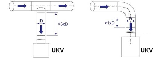
For the pressure control damper the minimum safety distance for the static measurement tab after the control damper is 5xD. Please refer to job drawings.
Wiring
The wiring shall be carried out in accordance with local regulations and by professional technicians.
For the power supply of all control options, a safety-isolating transformer shall be used.
The wiring instructions are presented following applications:
1 A UKV; CU=EM / EK / EC / EE Typical variable airflow control application
1 B UKV; CU=EM / EK / EC / EE Overriding controls
1 C UKV; CU=EM / EK / EC / EE Example; variable airflow control with a room controller
1 D UKV; CU=EM / EK / EC / EE Example; variable airflow control with a building management system
1 E UKV; CU=EM / EK / EC / EE Example: parallel airflow control with a building management system
3 A UKV; CU=EG Typical variable airflow controll
3 B UKV; CU=EG Position & constant airflow control
Control units
CU Description Note
EM LMV-D3-MF-F.1 HI 5 Nm
EK NMV-D3-MF-F.1 HI 10 Nm
EC LMV-D3-MP-F.1 HI 5 Nm, with MP-bus
EE NMV-D3-MP-F.1 HI 10 Nm, with MP-bus
EG GLB181.1E/3 10 Nm
1A & 1B
Example: UKV;
CU = EM / EC (LMV-D3-MP/MF HI) or EK / EE (NMV-D3-MP/MF HI)
– typical application and overriding controls
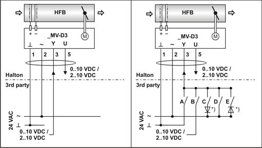
1A Typical variable airflow control application 1B Overrides All options
Code description
Halton Delivered by Halton
3rd party Delivered by a third party
ACD UKV
1 (G0) 24 VAC system neutral
2 (~) 24 VAC live
3 (Y) 2…10- or 0…10-VDC airflow setpoint signal input
5 (U5) 2…10- or 0…10-VDC airflow feedback signal output
*) Diode 1N 4007
Operating mode
| 2…10 VAC | 0…10 VAC | A | B | C | D | E | |
| NA | NA | ON | |||||
| qv_min | qv_min | Off | Off | Off | Off | Off | Constant flow |
| Variable qv_min…qv_max |
Variable qv_min…qv_max |
Off | ON | Off | Off | Off | |
| CLOSED | CLOSED | Off | Off | ON | Off | Off | |
| qv_max | qv_max | Off | Off | Off | ON | Off | Constant flow |
| OPEN | OPEN | Off | Off | Off | Off | ON |
Shut-off with control signal w:
In addition to relay override command situations, the damper will be fully closed if:
- 0…10 VDC: the UKV minimum airflow is set to 0% (0 l/s or 0 m3/h) and control signal w falls below 0.45 VDC
- 2…10 VDC : the UKV control signal w falls below 0.5 VDC
- Both 0…10 VDC and 2…10 VDC: the airflow setpoint voltage falls below a value corresponding to an air velocity of less than 0.5 m/s
| Mode | Voltage of w, VDC |
Function |
| 0…10 VDC | 0.0…0.45 | Minimum airflow (closed if qv_min = 0%) |
| 0.5…10.0 | Modulating, qv_min … qv_max | |
| 10.0 | Maximum airflow | |
| 2…10 VDC | 0.0…0.5 | Damper closed |
| 0.5…2.0 | Minimum airflow | |
| 2.0…10.0 | Modulating, qv_min…qv_max | |
| 10.0 | Maximum airflow |
1C & 1D
Example: UKV;
CU = EM / EC (LMV-D3-MP/MF HI) or EK / EE (NMV-D3-MP/MF HI)
– variable airflow control with a room controller or a building management system
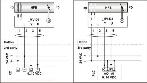
1C Room controller application 1D Building management system application application
Code description
Halton Delivered by Halton
3rd party Delivered by a third party
ACD UKV
1 (G0) 24 VAC system neutral
2 (~) 24 VAC live
3 (w) 0…10-VDC airflow setpoint signal input
5 (U5) 0…10-VDC airflow feedback signal output
RC Room controller
PLC Building management system
C (AO) Airflow setpoint control signal
F (AI) Actual airflow feedback input
1E
Example: UKV;
CU = EM / EC (LMV-D3-MP/MF HI) or EK / EE (NMV-D3-MP/MF HI)
– parallel airflow control with a building management system
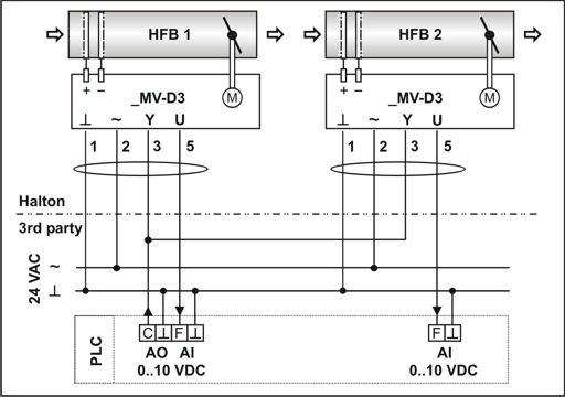
1E Parallel airflow control with building management system
Code description
Halton Delivered by Halton
3rd party Delivered by a third party
ACD1 UKV supply
ACD3 Exhaust
1 (G0) 24 VAC system neutral
2 (~) 24 VAC live
3 (w) 0…10-VDC airflow setpoint signal input
5 (U5) 0…10-VDC airflow feedback signal output
PLC Building management system
C (AO) Airflow setpoint control signal
F (AI) Actual airflow feedback input
3A & 3B
Example: UKV;
CU=EG (GLB181.1E/3)
– typical variable airflow control and position & constant airflow control
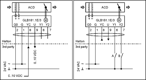
3A Typical airflow control application 3B Position & constant airflow control
Code description
Halton Delivered by Halton
3rd party Delivered by a third party
ACD UKV
2 (G0) 24 VAC system neutral
1 (G) 24 VAC live
8(YC) 2…10- or 0…10-VDC airflow setpoint signal input
9 (U) 2…10- or 0…10-VDC airflow feedback signal output
6 (Y1) Override input
7 (Y2) Override input
| Constant flow | A | B |
| CLOSED | Off | ON |
| Min. flow | Off | Off |
| Max. flow | ON | ON |
| OPEN | ON | Off |
Commissioning
Airflow control
Nominal airflow rates of the Halton UKV are presented in the table below.
| l/s | W [mm] | |||||||
| H [mm] | 200 | 400 | 600 | 800 | 1000 | 1200 | 1400 | 1600 |
| 200 | 516 | 1033 | 1549 | 2065 | 2582 | 3098 | 3614 | 4131 |
| 300 | 775 | 1549 | 2324 | 3098 | 3873 | 4647 | 5422 | 6196 |
| 400 | 1033 | 2065 | 3098 | 4131 | 5164 | 6196 | 7229 | 8262 |
| 500 | 1291 | 2582 | 3873 | 5164 | 6454 | 7745 | 9036 | 10327 |
| 600 | 1549 | 3098 | 4647 | 6196 | 7745 | 9294 | 10843 | 12392 |
| 700 | 1807 | 3614 | 5422 | 7229 | 9036 | 10843 | 12651 | 14458 |
| 800 | 2065 | 4131 | 6196 | 8262 | 10327 | 12392 | 14458 | 16523 |
| 900 | 2324 | 4647 | 6971 | 9294 | 11618 | 13942 | 16265 | 18589 |
| 1000 | 2582 | 5164 | 7745 | 10327 | 12909 | 15491 | 18072 | 20654 |
| m3/h | W [mm] | |||||||
| H [mm] | 200 | 400 | 600 | 800 | 1000 | 1200 | 1400 | 1600 |
| 200 | 1859 | 3718 | 5577 | 7435 | 9294 | 11153 | 13012 | 14871 |
| 300 | 2788 | 5577 | 8365 | 11153 | 13942 | 16730 | 19518 | 22306 |
| 400 | 3718 | 7436 | 11153 | 14871 | 18598 | 22306 | 26024 | 29742 |
| 500 | 4647 | 9294 | 13942 | 18589 | 23236 | 27883 | 32530 | 37177 |
| 600 | 5577 | 11153 | 16730 | 22306 | 27883 | 33460 | 39036 | 44613 |
| 700 | 6506 | 13012 | 19518 | 26024 | 32530 | 39036 | 45542 | 52048 |
| 800 | 7435 | 14871 | 22306 | 29742 | 37177 | 44613 | 52048 | 59484 |
| 900 | 8365 | 16730 | 25095 | 33460 | 41825 | 50189 | 58554 | 66919 |
| 1000 | 9294 | 18589 | 27883 | 37177 | 46472 | 55766 | 65060 | 74355 |
The actual measured airflow rate (qv) can be defined by the controller feedback signal (U or U5) and airflow controller nominal airflow (qv_nom).
| Signal | Formula | Controller type and mode | Terminals system neutral |
Terminals signal |
| 0…10 VDC |
qv=qv_nom*U/10 | UKV;CU=EM, EK, EC or EE (LMV-D3-MP/MF HI or NMV-D3-MP/MF HI), mode 0…10 VUKV;CU=EG (GLB181.1E/3) |
1 (GND)
2(G0) |
5 (U5)
9(U) |
| 2…10 VDC |
qv=qv_nom*(U-2)/8 | UKV;CU=EM, EK, EC or EE (LMV-D3-MP/MF HI or NMV-D3-MP/MF HI), mode 2…10 V |
1 (GND) | 5 (U5) |
The actual airflow rate can also be determined from the pictures below.
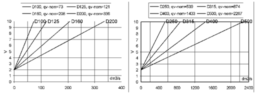
The actual airflow rate can be calculated as a function of differential pressure at the measurement probe and the measurement probe k factor. The proper k factor can be found in an attachment for the product.
qv Actual airflow rate [l/s]
k k factor value: W [mm] x H [mm] x 0,001054
Δpm Differential pressure of measurement probe [Pa]
The Halton UKV airflow controller is equipped with a pressure sensor, and there is a very low airflow through the differential pressure sensor of the controller. Therefore, a manual differential measurement manometer can be connected in parallel to the airflow controller (for example with tube T-branches) and both measurements can operate in parallel with continuous control.
If Halton UKV is ordered without factory pre-set minimum and maximum flow values (FS=NA), minimum flow value will be set to 0 and maximum flow value is equal to nominal flow value.
Specification
The pressure-independent variable airflow control damper shall be made of galvanised steel, with an airflow measurement probe of aluminium.
The tightness of the control damper in closed position shall conform to standard EN1751 class 1 and casing tightness to EN 1751/C.
The management damper section shall contain airflow measurement, flow controller and damper actuator.
Design airflow range limits shall be calibrated at the factory.
Controller settings shall be adjustable on site with a PC or a handheld tool.
The airflow controller shall have control signal input 0…10 VDC or 2 …10 VDC and output 0…10 VDC or 2…10VDC for airflow feedback.
Supply power shall be 24 VAC.
Order code
UKV-W-H; MA-MD-MO-ZT
| Main options | |
| W = Width, diameter of duct connection [mm] | 200, 250,300, … 1600, with increment of 50 mm |
| H = Height, diameter of duct connection [mm] | 200, 250, 300, … 1000, with increment of 50 mm |
| Other options and accessories | |
| MA = Material | |
| CS | Galvanized steel |
| MD = Model | |
| N | No insulation |
| I1 | Insulated 15 mm |
| I2 | Insulated 30 mm |
| MO = Controller | |
| EM | LMV-D3-MF-F.1 HI (DC 0/2…10 V), 5 Nm |
| EK | NMV-D3-MF-F.1 HI (DC 0/2…10 V), 10 Nm |
| EC | LMV-D3-MP (MP bus), 5 Nm |
| EE | NMV-D3-MP (MP bus), 10 Nm |
| EG | GLB181.1E/3 (DC 0/2…10V), 10 Nm |
| ER | LMV-D3-KNX (KNX bus), 5 Nm |
| ES | NMV-D3-KNX (KNX bus), 10 Nm |
| ET | LMV-D3-MOD (Modbus RTU), 5 Nm |
| EU | NMV-D3-MOD (Modbus RTU), 10 Nm |
| EH | GDB181.1E/3 (DC 0/2…10 V), 5 Nm |
| EG | GLB181.1E/3 (DC 0/2…10V), 10 Nm |
| EV | GDB181.1E/KN (KNX bus), 5 Nm |
| EW | GLB181.1E/KN (KNX bus), 10 Nm |
| EB | GDB181.1E/MO (Modbus RTU), 5 Nm |
| EF | GLB181.1E/MO (Modbus RTU), 10 Nm |
| V1 | LM24A-VST, (DC 0/2…10 V), 5 Nm+VRU-D3-BAC |
| V2 | NM24A-VST, (DC 0/2…10 V), 10Nm+VRU-D3-BAC |
| V3 | LMQ24A-VST, 2.5 sec (DC 0/2…10 V), 4 Nm+VRU-D3-BAC |
| V4 | NMQ24A-VST, 4 sec (DC 0/2…10 V), 8 Nm+VRU-D3-BAC |
| ZT = Tailored product | |
| N | No |
| Y | Yes (ETO) |
Order code example
UKV-400-200; MA=CS, MD=I1, MO=EE, ZT=N
Downloads
"*" indicates required fields
ABD – Automated Balancing Damper for kitchen ventilation (CE)
product
ABD – Automatic balancing damper for kitchen ventilation (ETL)
product
CID-01 – Zero leakage isolation damper
product
Halton BOX – Airflow management unit (VAV)
product
Halton Max MDC – Zone control damper for Halton Workplace system
product
Halton Max MLC – Airflow management damper (VAV)
product
Halton Max MOC – Airflow management damper (VAV)
product
Halton Max MOS – Airflow management damper (VAV)
product
Halton Max MSB – Slim airflow management damper (VAV)
product
Halton Max MUC – Ultrasound airflow management damper (VAV)
product

Halton PRA – Airflow management damper (CAV)
product
Halton PTS – Airflow management damper (single-blade)
product
Halton RMC – Airflow management damper (CAV)
product
Halton SA – Sound attenuator
product
Halton UKV – Airflow management damper (VAV)
product
Halton UTK – Multi-blade airflow management damper (CAV)
product
Halton UTT – Multi-blade airflow management damper (CAV)
product

Halton Vita VLR – Room airflow controller for Halton Vita Lab solutions
product
Halton Vita VLS – Fume cupboard controller for Halton Vita Lab solutions
product
KBD – Exhaust hood balancing damper (ETL)
product