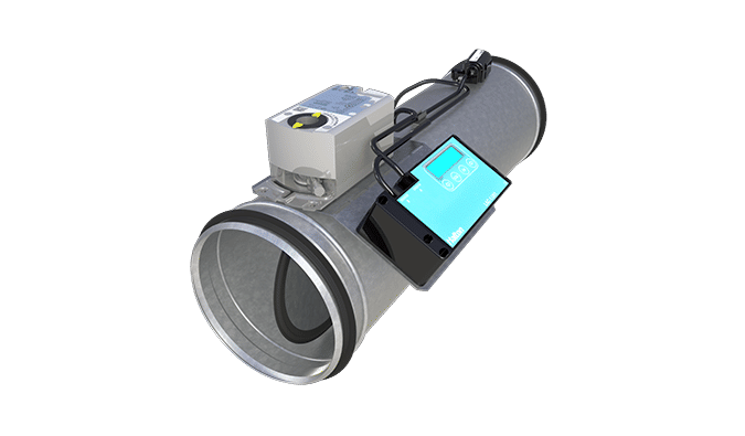
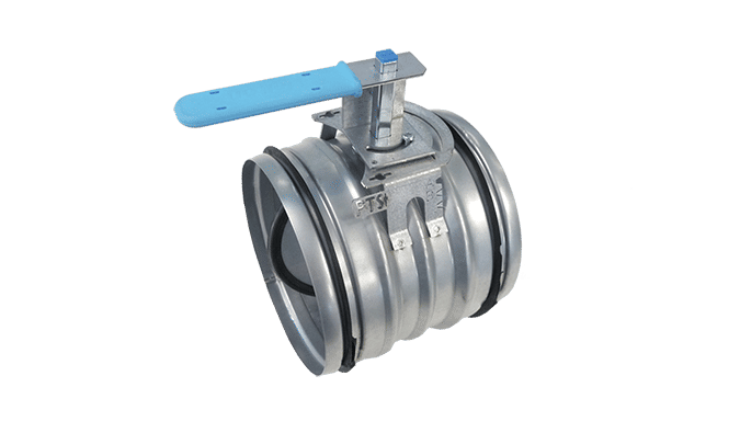
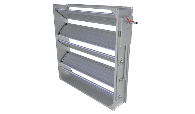
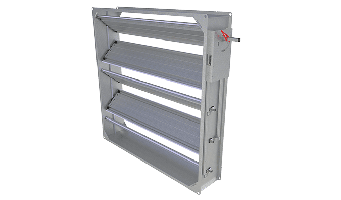
Product / PRA
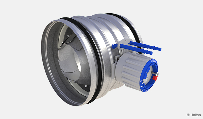
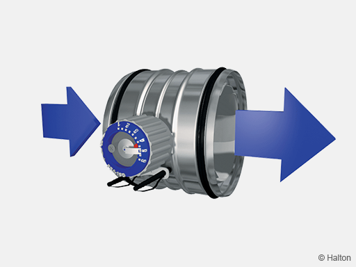
Halton PRA – Airflow management damper (CAV)
Quiet, accurate, easy to install due to compact size, easy to adjust. The best seller of its category and legendary product of Halton which has been sold in millions.
- Duct cleaning enabled through the unit up to size 315 mm
- Accurate airflow measurement based on flow nozzle principle

Overview
- Airflow balancing, adjustment and measurement functions
- Manual adjustment, no tools required
- Accurate airflow measurement based on flow nozzle principle
- Minimised sound generation due to conical adjustment section
- Temperature operation range from -30 °C to +70 °C
- Self-locking adjustment mechanism, position can be ensured with locking screw
- Duct cleaning enabled through the unit up to size 315 mm
- Adjustment position marker indicates proper position e.g. repositioning after cleaning
- Inlet and outlet spigots equipped with integral rubber gaskets
- Used also as supply air jet nozzle for air diffusion in large spaces
- Classification of casing leakage EN 1751 class C
Quick selection
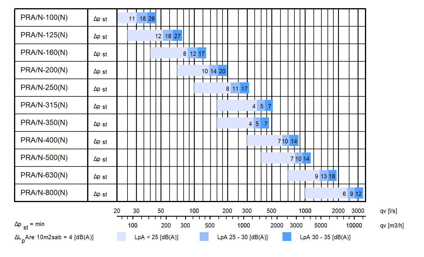
Dimensions and weight
Halton PRA 100…315
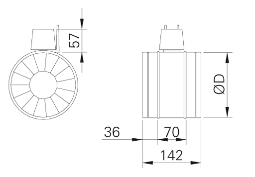
| NS | ØD |
| 100 | 99 |
| 125 | 124 |
| 160 | 159 |
| 200 | 199 |
| 250 | 249 |
| 315 | 314 |
Halton PRA 350…800
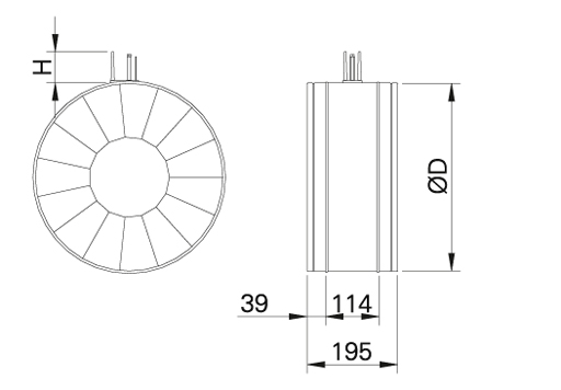
| NS | ØD | H |
| 350 | 349 | 70 |
| 400 | 399 | 70 |
| 500 | 499 | 70 |
| 630 | 629 | 70 |
| 800 | 799 | 70 |
Weight [kg]
| NS | PRA/N |
| 100 | 0.4 |
| 125 | 0.5 |
| 160 | 0.7 |
| 200 | 0.9 |
| 250 | 1.2 |
| 315 | 1.6 |
| 400 | 4.5 |
| 500 | 6.1 |
| 630 | 9.4 |
Material
| Part | Material | Note |
| Casing | Galvanised steel | – |
| Blades | Galvanised steel | – |
| Operating mechanism | ABS and PBT plastic | Sizes 100…315 |
| Operating mechanism | Steel | Sizes 350…800 |
| Duct gaskets | 1C-polyurethane hybrid | – |
| Measurement taps | Polyurethane (PU) | – |
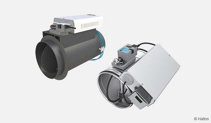
Function
The airflow rate is adjusted by turning the adjustment knob in order to change the aperture size of the adjustment cone formed by iris blades. Once the opening area is reduced, the airflow rate decreases and the total pressure loss caused by the device increases.
The airflow can be determined by measuring the differential pressure in the measurement taps.
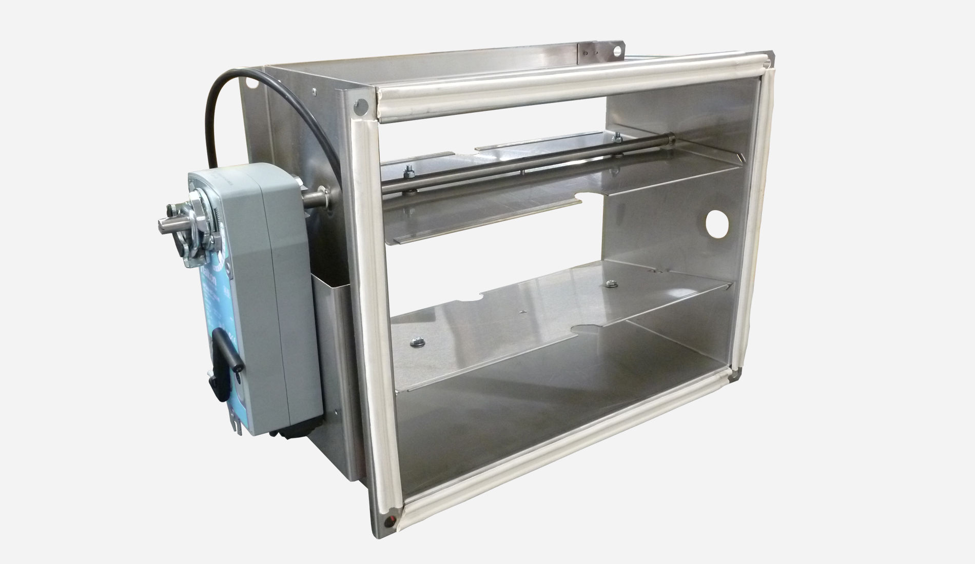
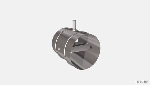
Halton PRA 100…315 mm
The operating mechanism is positioned partly outside the device and between the adjustment cone and casing. The unit can be cleaned with normal duct sweeping equipment when the device is fully opened .
Halton PRA 350…800 mm
The operating mechanism is located partly outside the device and inside the adjustment cone. The unit can be cleaned with normal duct sweeping equipment, when the device is fully opened. The cleaning equipment is passed carefully through the operating mechanism.
Supply air jet nozzle PRA/S
The Halton PRA-unit can also be used as a supply air nozzle in e.g. industrial spaces. Refer to the technical data for Halton PRA/S -model presented in the technical performance chapter.
Installation
Sizes 100…315 mm
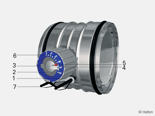
Code description
1. Air flow direction indicator
2. Adjustment knob
3. Locking screw or adjusment position
4. Adjustment position indicator
5. Adjustment position marker for cleaning
6. Adjustment scale
7. Measurement taps
Sizes 350…800 mm
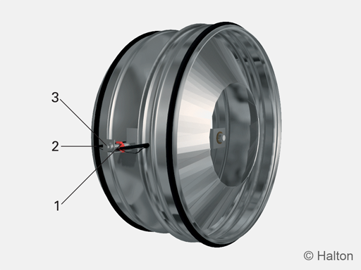
Code description
1. Adjustment position indicator
2. Adjustment knob
3. Measurement taps
Fix the damper to the ductwork e.g. with rivets. Ensure that the rivet does not prevent the operation of the Halton PRA. The position of the rivet must be at least 10 mm from the duct end.
The Halton PRA iris damper shall be installed in the ductwork taking into account the safety distances outlined in the installation guidelines.
The orientation of the unit shall correspond to the airflow direction. The airflow direction is marked with an arrow indicator on the label on the casing . In order to get accurate measurement readings the orientation of the unit shall be selected so that the location of the measurement taps (below the knob) corresponds to the installation guidelines.
Safety distances
Recommended safety distance in order to get accurate measurement readings are presented in the figure below.
Direct duct with no flow disturbances
- Safety distance 4 D upflow of the Halton PRA unit
- Safety distance 1 D downflow of the Halton PRA unit
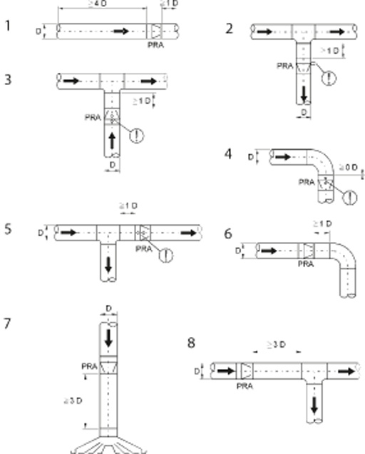
In cases where recommended safety distances cannot be met, use the correction factors of the attached figures for determination of the airflow rate.
Note the position of the measurement taps marked in the figures.
| Figure | Installation case | Duct velocity upflow of the PRA unit |
k-factor |
| 1 | Direct duct | 1 | |
| 2 | T-branch, supply air | 0.95 (1D) …1.00 (4D) | |
| 3 | T-branch, exhaust air | > 2 m/s 1…2 m/s |
0.95 (1D) …1.00 (4D) 0.90 (1D) …1.00 (4D) |
| 4 | 90° bend | 0.97 (0D) …1.00 (4D) | |
| 5 | T-branch | 1 | |
| 6 | 90° bend | 1 | |
| 7 | Upflow of a supply air device | 1 | |
| 8 | T-branch | 1 |
Adjustment
Set the adjustment knob in the desired adjustment position (pre-set position if available).
The airflow rate is determined by measuring the differential pressure in measurement tabs using a manometer.
The flow rate is calculated using the formula below:
k-factor is retrieved in both the tables presented below and in installation guidelines. k-factor depends on the unit size and adjustment position (a).
Note that when recommended safety distances are not met, the correction factors for the installation case shall be used.
Halton PRA 100, k-factor
| Units | Airflow (q v ) [l/s] Differential pressure (dp m ) [Pa] |
Airflow (q v ) [m3/h] Differential pressure (dp m ) [Pa] |
Airflow (q v ) [cfm] Differential pressure (dp m ) [in WC] |
| Opening a | |||
| 1 | 1.8 | 6.5 | 60.2 |
| 1.5 | 2.1 | 7.6 | 70.2 |
| 2 | 2.4 | 8.6 | 80.3 |
| 2.5 | 2.7 | 9.7 | 90.3 |
| 3 | 3.1 | 11.2 | 103.7 |
| 3.5 | 3.6 | 13.0 | 120.4 |
| 4 | 4.1 | 14.8 | 137.1 |
| 4.5 | 4.7 | 16.9 | 157.2 |
| 5 | 5.5 | 19.8 | 183.9 |
| 5.5 | 6.4 | 23.0 | 214.0 |
| 6 | 7.8 | 28.1 | 260.8 |
Halton PRA 125, k-factor
| Units | Airflow (q v ) [l/s] Differential pressure (dp m ) [Pa] |
Airflow (q v ) [m3/h] Differential pressure (dp m ) [Pa] |
Airflow (q v ) [cfm] Differential pressure (dp m ) [in WC] |
| Opening a | |||
| 1 | 2.5 | 9.0 | 83.6 |
| 1.5 | 2.9 | 10.4 | 97.0 |
| 2 | 3.3 | 11.9 | 110.3 |
| 2.5 | 3.8 | 13.7 | 127.1 |
| 3 | 4.4 | 15.8 | 147.1 |
| 3.5 | 5 | 18.0 | 167.2 |
| 4 | 5.9 | 21.2 | 197.3 |
| 4.5 | 6.8 | 24.5 | 227.4 |
| 5 | 7.9 | 28.4 | 264.2 |
| 5.5 | 9.5 | 34.2 | 317.7 |
| 6 | 11.6 | 41.8 | 387.9 |
Halton PRA 160, k-factor
| Units | Airflow (q v ) [l/s] Differential pressure (dp m ) [Pa] |
Airflow (q v ) [m3/h] Differential pressure (dp m ) [Pa] |
Airflow (q v ) [cfm] Differential pressure (dp m ) [in WC] |
| Opening a | |||
| 1 | 4.1 | 14.8 | 137.1 |
| 1.5 | 4.7 | 16.9 | 157.2 |
| 2 | 5.5 | 19.8 | 183.9 |
| 2.5 | 6.4 | 23.0 | 214.0 |
| 3 | 7.6 | 27.4 | 254.1 |
| 3.5 | 9 | 32.4 | 300.9 |
| 4 | 10.6 | 38.2 | 354.4 |
| 4.5 | 12.6 | 45.4 | 421.3 |
| 5 | 15 | 54.0 | 501.6 |
| 5.5 | 18.2 | 65.5 | 608.6 |
| 6 | 22.9 | 82.4 | 765.7 |
Halton PRA 200, k-factor
| Units | Airflow (q v ) [l/s] Differential pressure (dp m ) [Pa] |
Airflow (q v ) [m3/h] Differential pressure (dp m ) [Pa] |
Airflow (q v ) [cfm] Differential pressure (dp m ) [in WC] |
| Opening a | |||
| 1 | 7.1 | 25.6 | 237.4 |
| 1.5 | 8 | 28.8 | 267.5 |
| 2 | 8.8 | 31.7 | 294.3 |
| 2.5 | 10 | 36.0 | 334.4 |
| 3 | 11.4 | 41.0 | 381.2 |
| 3.5 | 13.1 | 47.2 | 438.0 |
| 4 | 15.1 | 54.4 | 504.9 |
| 4.5 | 17.5 | 63.0 | 585.2 |
| 5 | 20.5 | 73.8 | 685.5 |
| 5.5 | 24.2 | 87.1 | 809.2 |
| 6 | 29 | 104.4 | 969.7 |
Halton PRA 250, k-factor
| Units | Airflow (q v ) [l/s] Differential pressure (dp m ) [Pa] |
Airflow (q v ) [m3/h] Differential pressure (dp m ) [Pa] |
Airflow (q v ) [cfm] Differential pressure (dp m ) [in WC] |
| Opening a | |||
| 1 | 10.5 | 37.8 | 351.1 |
| 1.5 | 11.9 | 42.8 | 397.9 |
| 2 | 13.8 | 49.7 | 461.4 |
| 2.5 | 16.1 | 58.0 | 538.3 |
| 3 | 18.9 | 68.0 | 632.0 |
| 3.5 | 22 | 79.2 | 735.6 |
| 4 | 25.6 | 92.2 | 856.0 |
| 4.5 | 30.1 | 108.4 | 1006.5 |
| 5 | 35.8 | 128.9 | 1197.1 |
| 5.5 | 42.9 | 154.4 | 1434.5 |
| 6 | 52.8 | 190.1 | 1765.5 |
Halton PRA 315, k-factor
| Units | Airflow (q v ) [l/s] Differential pressure (dp m ) [Pa] |
Airflow (q v ) [m3/h] Differential pressure (dp m ) [Pa] |
Airflow (q v ) [cfm] Differential pressure (dp m ) [in WC] |
| Opening a | |||
| 1 | 18.3 | 65.9 | 611.9 |
| 1.5 | 21.8 | 78.5 | 728.9 |
| 2 | 26 | 93.6 | 869.4 |
| 2.5 | 30.7 | 110.5 | 1026.5 |
| 3 | 36.5 | 131.4 | 1220.5 |
| 3.5 | 43.3 | 155.9 | 1447.8 |
| 4 | 51.3 | 184.7 | 1715.3 |
| 4.5 | 61.5 | 221.4 | 2056.4 |
| 5 | 74.3 | 267.5 | 2484.4 |
| 5.5 | 92.6 | 333.4 | 3096.3 |
| 6 | 120.2 | 432.7 | 4019.2 |
Halton PRA 350, k-factor
| Units | Airflow (q v ) [l/s] Differential pressure (dp m ) [Pa] |
Airflow (q v ) [m3/h] Differential pressure (dp m ) [Pa] |
Airflow (q v ) [cfm] Differential pressure (dp m ) [in WC] |
| Opening a | |||
| 1 | 17.6 | 63.4 | 588.5 |
| 2 | 24.3 | 87.5 | 812.5 |
| 3 | 35.2 | 126.7 | 1177.0 |
| 4 | 50 | 180.0 | 1671.9 |
| 5 | 71.6 | 257.8 | 2394.1 |
| 6 | 99 | 356. | 3310.3 |
Halton PRA 400, k-factor
| Units | Airflow (q v ) [l/s] Differential pressure (dp m ) [Pa] |
Airflow (q v ) [m3/h] Differential pressure (dp m ) [Pa] |
Airflow (q v ) [cfm] Differential pressure (dp m ) [in WC] |
| Opening a | |||
| 1 | 20.5 | 73.8 | 685.5 |
| 2 | 26.5 | 95.4 | 886.1 |
| 3 | 36.5 | 131.4 | 1220.5 |
| 4 | 55 | 198.0 | 1839.1 |
| 5 | 86 | 309.6 | 2875.6 |
| 6 | 137 | 493.2 | 4581 |
Halton PRA 500, k-factor
| Units | Airflow (q v ) [l/s] Differential pressure (dp m ) [Pa] |
Airflow (q v ) [m3/h] Differential pressure (dp m ) [Pa] |
Airflow (q v ) [cfm] Differential pressure (dp m ) [in WC] |
| Opening a | |||
| 1 | 27.5 | 99.0 | 919.5 |
| 2 | 39 | 140.4 | 1304.1 |
| 3 | 59 | 212.4 | 1972.8 |
| 4 | 86 | 309.6 | 2875.6 |
| 5 | 123 | 442.8 | 4112.8 |
| 6 | 175 | 630 | 5851.6 |
Halton PRA 630, k-factor
| Units | Airflow (q v ) [l/s] Differential pressure (dp m ) [Pa] |
Airflow (q v ) [m3/h] Differential pressure (dp m ) [Pa] |
Airflow (q v ) [cfm] Differential pressure (dp m ) [in WC] |
| Opening a | |||
| 1 | 65 | 234.0 | 2173.4 |
| 2 | 90 | 324.0 | 3009.4 |
| 3 | 115 | 414.0 | 3845.3 |
| 4 | 154 | 554.4 | 5149.4 |
| 5 | 202 | 727.2 | 6754.4 |
| 6 | 295 | 1062 | 9863 |
Halton PRA 800, k-factor
| Units | Airflow (q v ) [l/s] Differential pressure (dp m ) [Pa] |
Airflow (q v ) [m3/h] Differential pressure (dp m ) [Pa] |
Airflow (q v ) [cfm] Differential pressure (dp m ) [in WC] |
| Opening a | |||
| 1 | 98 | 352.8 | 3276.9 |
| 2 | 137 | 493.2 | 4581.0 |
| 3 | 198 | 712.8 | 6620.6 |
| 4 | 280 | 1008 | 9362.5 |
| 5 | 393 | 1414.8 | 13141.0 |
| 6 | 570 | 2052 | 19059.4 |
Halton PRA 1000, k-factor (size not available anymore)
| Units | Airflow (q v ) [l/s] Differential pressure (dp m ) [Pa] |
Airflow (q v ) [m3/h] Differential pressure (dp m ) [Pa] |
Airflow (q v ) [cfm] Differential pressure (dp m ) [in WC] |
| Opening a | |||
| 1 | 144 | 518.4 | 4815.0 |
| 2 | 220 | 792.0 | 7356.3 |
| 3 | 310 | 1116.0 | 10365.7 |
| 4 | 440 | 1584.0 | 14712.5 |
| 5 | 620 | 2232.0 | 20731.3 |
| 6 | 890 | 3204.0 | 29759.5 |
Servicing
Before cleaning of the ductwork, check that the actual adjustment position is ticked with the adjustment position marker. Open the Halton PRA damper fully by turning the adjustment knob counter-clockwise.
Clean the ductwork carefully by sweeping equipment.
Reset the damper position to the marked adjustment position.
Specification
The adjustment damper comprisse an adjustable cone and airflow measurement taps for differential pressure measurement.
The casing and adjustment cone vanes are be made of galvanised steel.
The airflow determination is based on the differential pressure measurement caused by airflow over the damper cone.
The adjustment damper has an adjustment position indicator and adjustment position marker to be used during cleaning.
Halton recommends to use hatch or hatches on one or both side of the damper for inspection and cleaning. The hatch or hatches shall be located near the damper.
Order code
PRA/S-D-ZT
S = Model
N Standard
D = Duct connection size 8mm]
100, 125, 160, 200, 250, 315, 350, 400, 500, 630, 800
Other options and accessories
ZT = Tailored product
N No
Y Yes (ETO)
Code example
PRA/N-100, ZT=N
Downloads
"*" indicates required fields
ABD – Automated Balancing Damper for kitchen ventilation (CE)
product
ABD – Automatic balancing damper for kitchen ventilation (ETL)
product
CID-01 – Zero leakage isolation damper
product
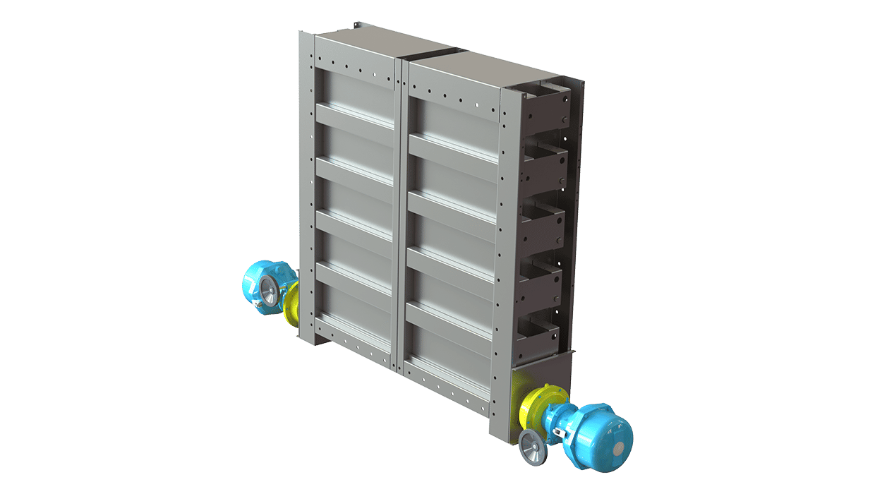
Halton BOX – Airflow management unit (VAV)
product
Halton Max MDC – Zone control damper for Halton Workplace system
product
Halton Max MLC – Airflow management damper (VAV)
product
Halton Max MOC – Airflow management damper (VAV)
product
Halton Max MOS – Airflow management damper (VAV)
product
Halton Max MSB – Slim airflow management damper (VAV)
product
Halton Max MUC – Ultrasound airflow management damper (VAV)
product
Halton PRA – Airflow management damper (CAV)
product
Halton PTS – Airflow management damper (single-blade)
product
Halton RMC – Airflow management damper (CAV)
product
Halton SA – Sound attenuator
product
Halton UKV – Airflow management damper (VAV)
product
Halton UTK – Multi-blade airflow management damper (CAV)
product
Halton UTT – Multi-blade airflow management damper (CAV)
product

Halton Vita VLR – Room airflow controller for Halton Vita Lab solutions
product
Halton Vita VLS – Fume cupboard controller for Halton Vita Lab solutions
product
KBD – Exhaust hood balancing damper (ETL)
product