Product / MUC
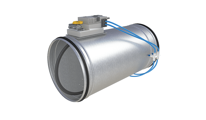
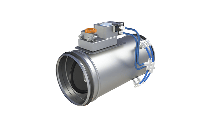
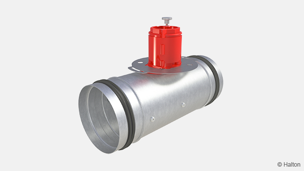
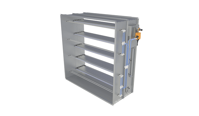
Halton Max MUC – Ultrasound airflow management damper (VAV)
Quick to install due to the individually pre-calibrated airflow values. This airflow damper is maintenance free because the dust doesn´t effect the measurement sensors.
Halton Max MUC has wide measurement range.
- Variable (VAV) and constant (CAV) airflow control applications
- Supply and exhaust installations
- Enables flexibility in terms of space layout design
- Available also for Halton Workplace applications
Overview
Circular airflow management damper using the ultrasound technique for airflow measurement.
Application areas
- Variable (VAV) and constant (CAV) airflow control applications
- Supply and exhaust installations
- Available also for Halton Workplace applications
Key features
- Insensitive to dust collection
- Enables flexibility in terms of space layout
- Individually calibrated for higher accuracies
- Low pressure loss for reducing the noise level
- Can be connected to Buildings Management System (BMS)
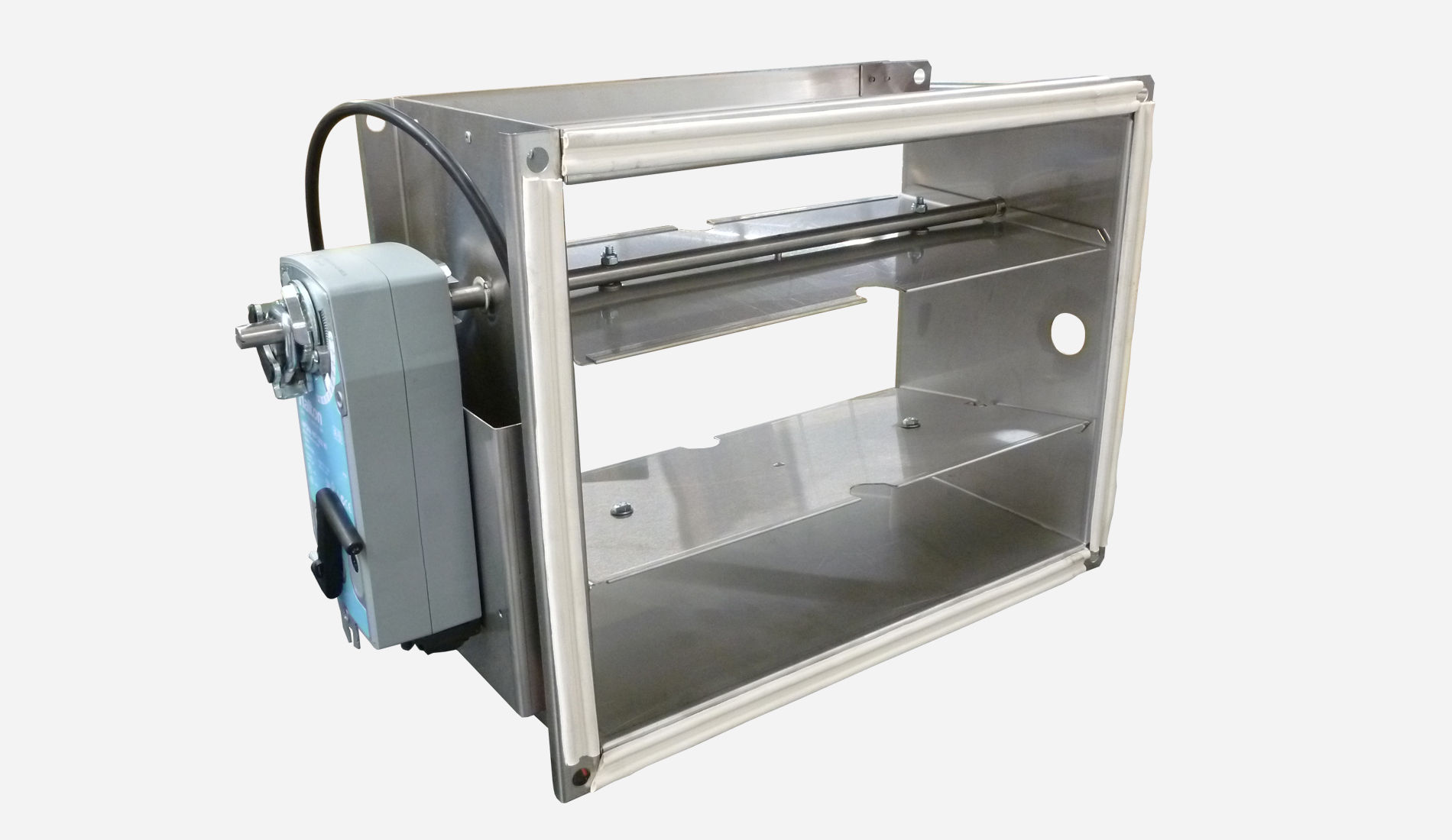
Operating principle
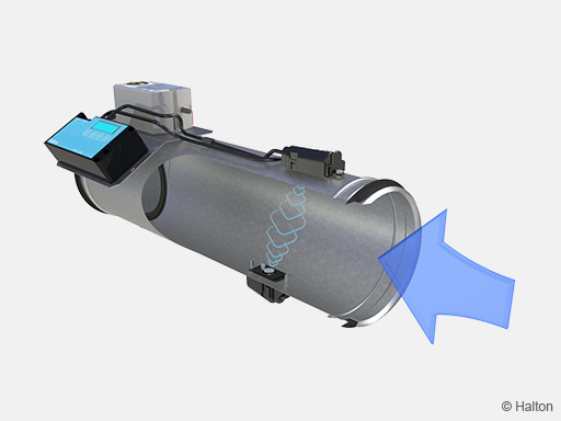
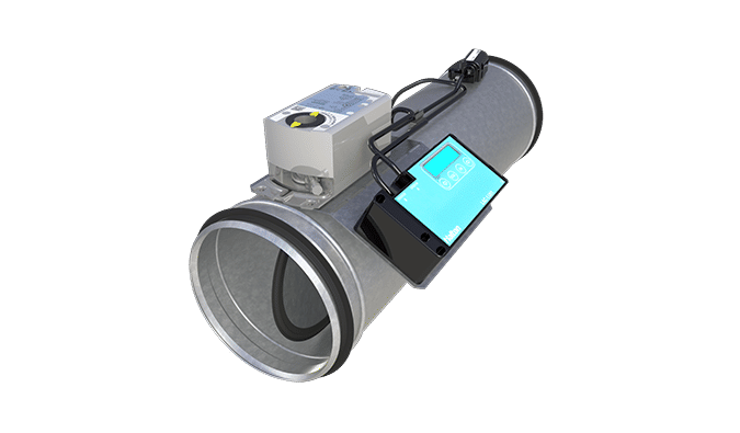
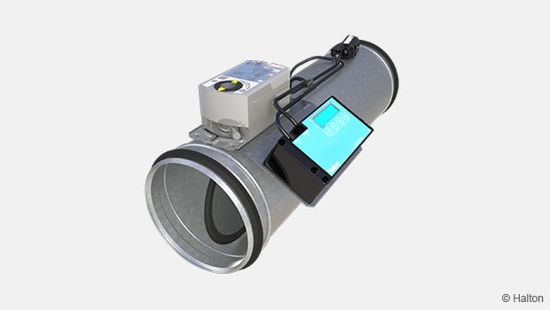
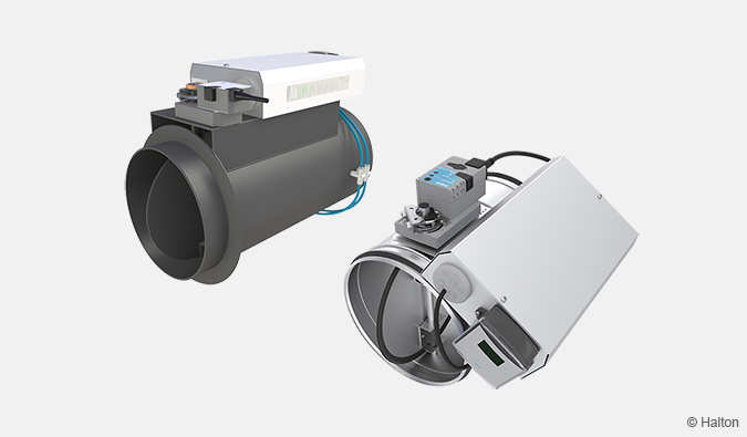
Fig.1. Halton Max MUC has two ultrasound sensors for airflow measurement.
The damper can function either as a supply or an exhaust unit. It maintains the required airflow through ultrasound measurement, regardless of airflow and pressure variations in the ductwork.
The damper has an airflow controller, two ultrasound sensors for airflow measurement, airflow temperature sensor and an actuator for controlling the damper blade. The airflow controller has a control panel for displaying the measurement values and setting the operation parameters.
The airflow controller can receive the airflow control signal via
- Modbus RTU network variable,
- the control panel input,
- an analogue standard signal.
All three control modes are synchronized between each other. The airflow measurement includes temperature and duct type compensations, providing accurate and reliable airflow measurements even at short distances from airflow disturbances in the ductwork.

Key technical data
|
Description |
Value |
| Duct connection sizes | ø100-630 |
| Material | Galvanised steel or stainless steel (EN 14404 / AISI 316L) |
| Air velocity range | 0.5 – 10 m/s |
| Operating range (ambient temperature) | 0-50℃ |
| Ambient relative humidity (non-condensing) |
< 95% |
| Communication interface | Modbus RTU, analogue |
| Accessories |
|
| Standards and certifications |
|
| Maintenance | Maintenance-free |
Quick selection
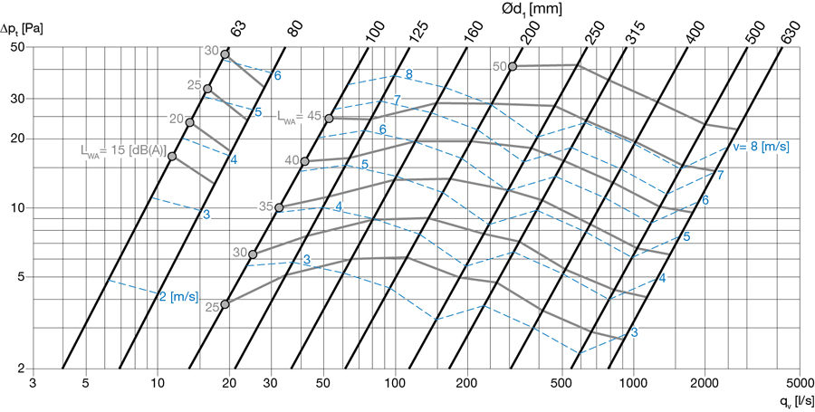
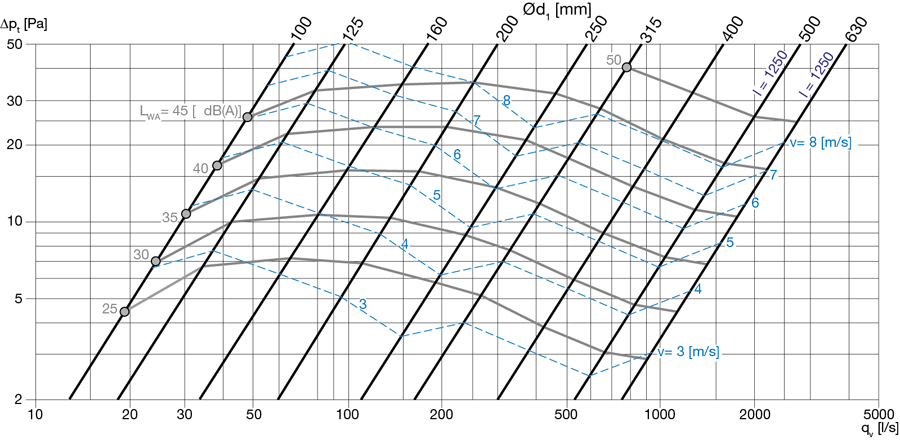
The operable airflow range for Halton Max MUC corresponds to duct air velocities 0.5 – 15 m/s.
The below example shows the airflow ranges and noise levels with air velocity 1-10 m/s.
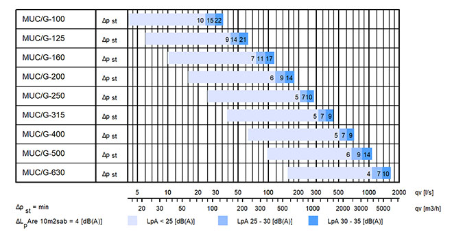
Fig.2. Quick selection for Halton Max Ultra MUC within air velocity range 0.5-10 m/s
NS |
qv min-max [l/s] |
qv min-max [m3/h] |
| 100 | 4 – 79 | 14 – 283 |
| 125 | 6 – 123 | 22 – 442 |
| 160 | 10 – 201 | 36 – 724 |
| 200 | 16 -315 | 55 – 1131 |
| 250 | 25 – 491 | 88 – 1767 |
| 315 | 39 – 779 | 140 – 2806 |
| 400 | 63 – 1257 | 226 – 4524 |
| 500 | 98 – 1963 | 353 – 7068 |
| 630 | 156 – 3117 | 561 – 11222 |
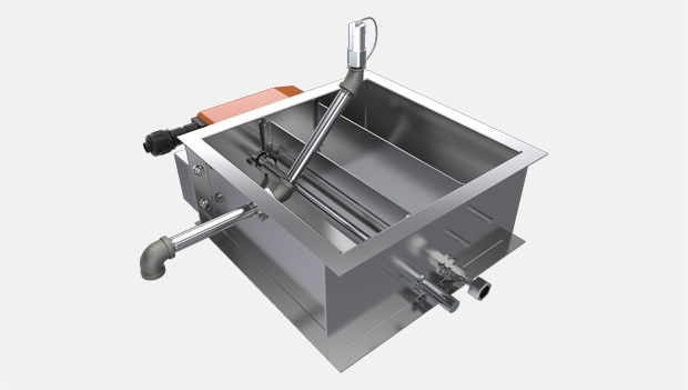
System package
Halton Workplace WRA room automation system package for Halton Max MUC airflow management damper
Halton Workplace WRA is part of the Halton Workplace solution offering.
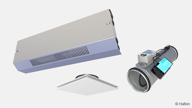
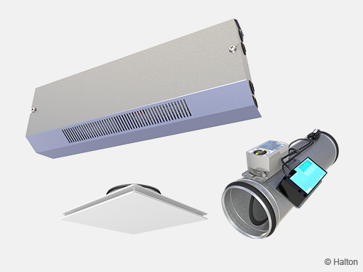
Fig.3. Halton Jaz JDA static diffuser and Halton Max MUC VAV damper combined with a Halton Workplace room automation controller.
Halton Workplace WRA is a controller especially designed for controlling the automation system of office spaces and meeting rooms. It is used for controlling the ventilation airflow, room temperature, and indoor air quality.
The Halton Workplace WRA room automation package consists of a controller unit and optional components depending on customer needs: a wall panel and sensors for temperature, CO2, occupancy, pressure, and condensation.
There are options available for the controller unit and wall panel, depending on the number of controls and sensors required. The Halton Workplace WRA room automation controller is always combined with other Halton products for adaptable and high-level indoor climate.
Application area
- Controlling the ventilation airflow, room temperature, and indoor air quality in office spaces and meeting rooms
- The Halton Workplace WRA room automation controller is an important part of the Halton Workplace system, controlling room units and airflow control dampers
- Overall Halton Workplace System includes:
- Room air conditioning applications with Halton Workplace WRA room automation controller:
- Active chilled beams
- Exhaust units
- VAV dampers
- Active VAV diffusers
- Room air conditioning applications with Halton Workplace WRA room automation controller:
- Halton Max MDC zone control damper
- Halton Workplace WSO system optimiser
Key features
- Factory-tested controller and wiring, easy to install
- Pre-installed project-specific parameters, quick to commission
- Several operating modes based on occupancy, thermal comfort, and indoor air quality
- Enables fully flexible layout solutions for changing needs in office environments
- Highly energy-efficient and reliable system operation
Operating principle
The Halton Workplace WRA room automation controller operates with Variable Air Volume (VAV) dampers and active chilled beams of the Halton Workplace system. These are used for adjusting the ventilation airflow, room temperature, and indoor air quality in office spaces.
Each room unit in an office space can have its own dedicated Halton Workplace WRA room automation controller, or a single controller can control multiple room units. The Halton Workplace WRA room automation controller can automatically adjust the system according to the indoor environment level preferred by users. Each room unit having its own dedicated controller brings maximum flexibility.
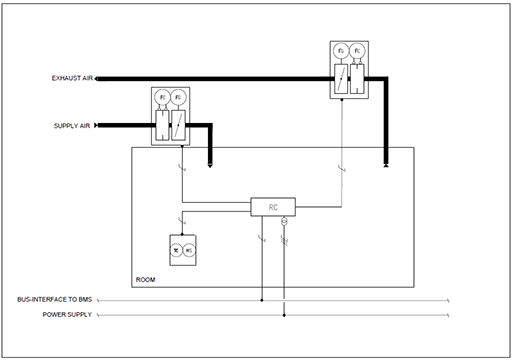
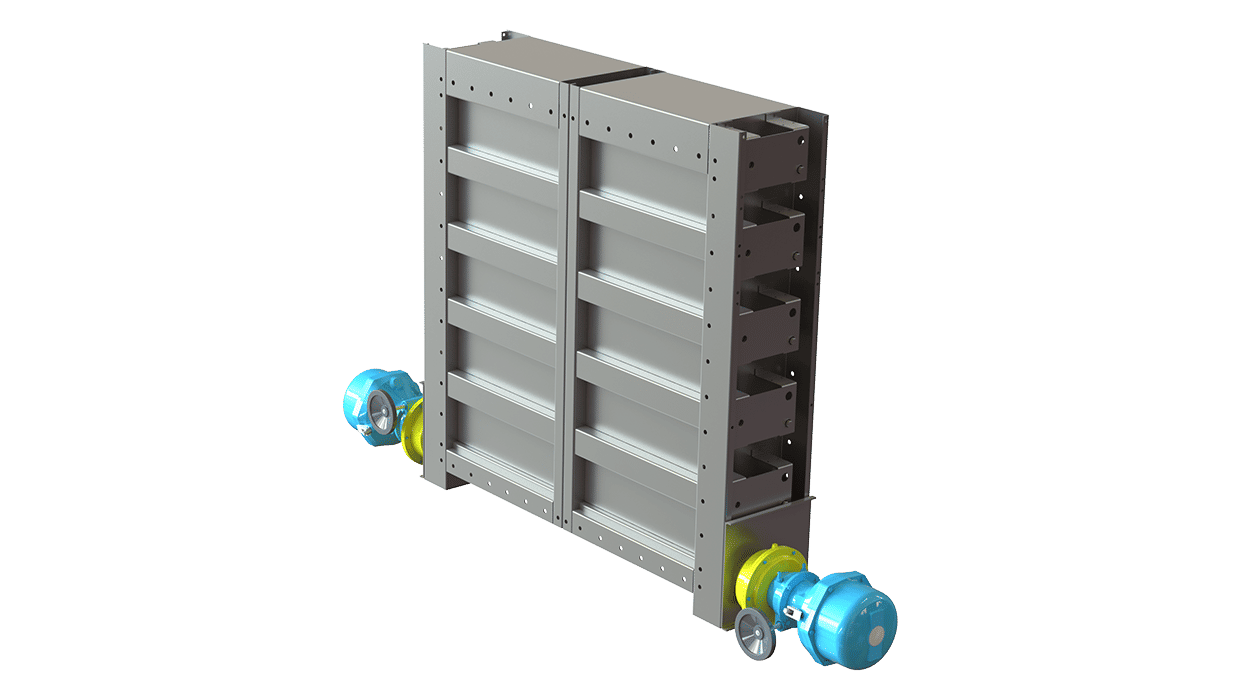
Room automation: Halton Jaz JDA and Halton Max MUC VAV damper controlled with Halton Workplace WRA room automation controller
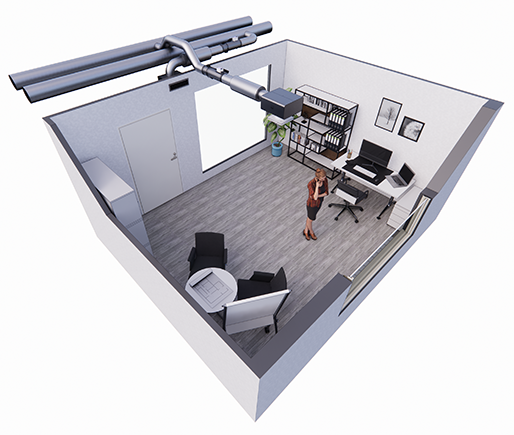
Fig.4. Halton Jaz JDA diffuser and Halton Max Ultra Circular VAV damper, controlled with Halton Workplace WRA room automation controller in a single office room
Room automation description
In this configuration, the Halton Workplace WRA room automation controller (type DXR2.E12P-102A) controls a Halton Jaz JDA diffuser that is combined with a Halton Max MUC VAV damper. External CO2 and occupancy sensors are installed in the room. The temperature sensor is integrated into the wall panel (type QMX3.P34). The system also includes an exhaust VAV damper and radiator heating water valve control. One Halton Workplace WRA room automation controller can individually control up to four room units, and there can be several Halton Workplace WRA room automation controllers in the room.
Design criteria for room automation
- Supply airflow control
- Exhaust airflow control
- Window switch control
- External CO2 and occupancy sensors
- Wall panel with temperature sensor and display
- Radiator heating water valve control
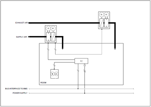
Schematic drawing

Fig.5. Schematic drawing: Halton Jaz JDA diffuser and Halton Max MUC VAV damper, controlled with Halton Workplace WRA room automation controller
Equipment list
| Code | Equipment |
| RC | Controller unit |
| FG | Airflow damper actuator |
| FC | Airflow measurement |
| H | Water valve actuator |
| OS | Occupancy sensor |
| CO2 | CO2 sensor |
| WP | Wall panel |
| TE | Temperature sensor |
| TI | Temperature display |
Wiring diagram
For the wiring diagram of similar configuration, see the product pages of the Halton Workplace WRA room automation controller.
Components and order code examples for the system
- 1 x Passive diffuser: Halton Jaz JDA
– JDA/S-125(R4) WS=NA, CO=W, ZT=N + TRI/S-125-125(N) - 1 x VAV damper: Halton Max Ultra Circular (MUC) or Halton Max MOC
– MUC/G-125, MA=CS - 1 x Exhaust unit: Halton AGC Exhaust grille + Halton PRL Plenum for grilles
– AGC/N-400-100 FS=CL, ME=A, FI=PN, CO=W, ZT=N+PRL/F-400-100-160 - 1 x VAV damper: Halton Max Ultra Circular (MUC) or Halton Max MOC
– MUC/G-160, MA=CS - Automation package: 1 x Halton Workplace WRA room automation controller unit with related components
– WRA/MUC-E21-MU -EX4, WP=34, LC=NA, SE=NA, SW=NA, ST=NA, SL=OE, PM=NA, TC=NA, CV=NA, RV=RA, ZT=N
Note: For more information, see the product pages of the Halton Workplace WRA room automation controller.
Structure and materials
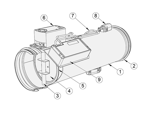
| No. | Part | Material |
| 1 | Casing | Galvanised steel or stainless steel (EN 14404/AISI316L) |
| 2 | Duct seal gasket | Rubber |
| 3 | Shaft | Galvanised steel or stainless steel (EN 14404/AISI316L) |
| 4 | Blade | Galvanised steel or stainless steel (EN 14404/AISI316L) |
| 5 | Blade gasket | EPDM rubber |
| 6 | Actuator | Plastic, steel, PVC cable |
| 7 | Cable | LSZH |
| 8 | Ultrasound sensor and temperature sensor | Plastic ABS |
| 9 | Airflow controller | Plastic ABS |
Control unit
Airflow control unit
The Halton Max MUC airflow controller LAC-1.UO1-controls the airflow using ultrasound technology. It provides accurate airflow measurements with two ultrasound sensors.
Technical data
|
Feature |
Description |
|---|---|
| Control concept |
|
| Power supply |
|
| Cables |
|
| Dimensions |
|
| Protection class |
|
Actuator
|
Code |
Notes |
Torque |
Damper size |
Communication interface |
Order code |
|
G2 |
Siemens actuator |
5 |
100-315 |
Siemens GDB 161.1E 0..10V/2..10V |
G2=GDB 161.1E |
|
G3 |
Siemens actuator |
10 |
400 – 500 |
Siemens GLB 161.1E |
G3=GLB 161.1E |
|
G4 |
Belimo actuator |
5 |
100-315 |
Belimo LM24A-SR 0..10V/2..10V |
G4=LM24A-SR |
|
G5 |
Belimo actuator |
10 |
400 – 500 |
Belimo NM24A-SR |
G5=NM24A-SR |
Dimensions and weight
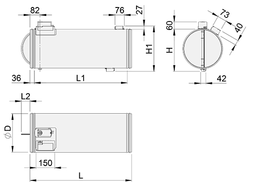
Fig.6. Halton Max MUC, D=100-315 mm
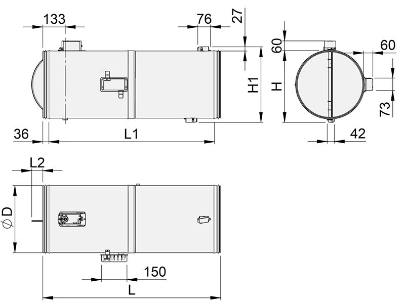
Fig.7. Halton Max MUC, D=400 mm
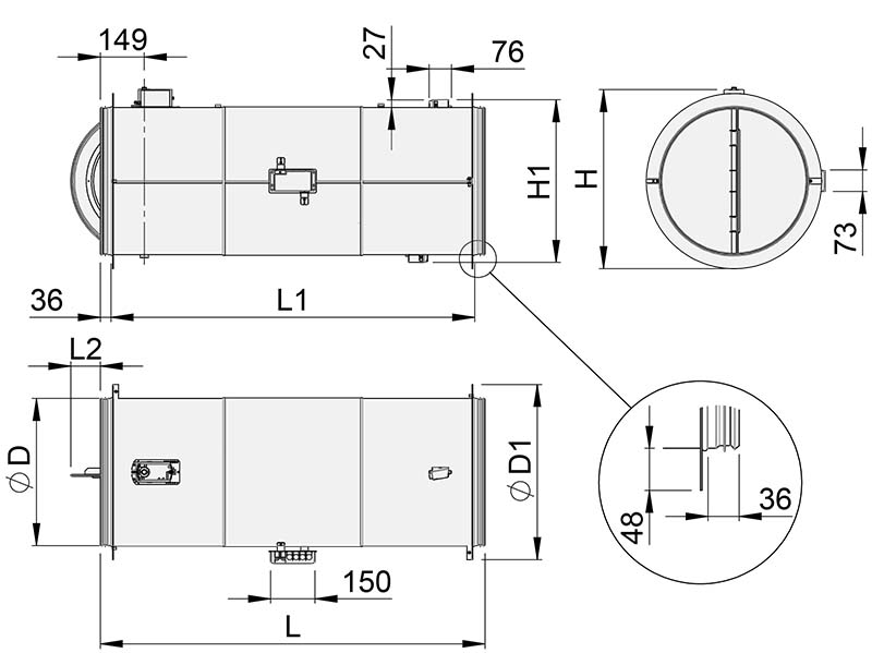
Fig.8. Halton Max MUC, D=500 and 630 mm
| NS |
ØD |
ØD1 |
L |
L1 |
L2 |
H |
H1 | Weight [kg] |
| 100 | 99 | – | 427 | 355 | – | 127 | 153 | 1.9 |
| 125 | 124 | – | 474 | 402 | – | 153 | 178 | 2.2 |
| 160 | 159 | – | 540 | 468 | – | 187 | 213 | 2.7 |
| 200 | 199 | – | 612 | 540 | 15 | 227 | 253 | 3.3 |
| 250 | 249 | – | 705 | 633 | 38 | 277 | 303 | 4.3 |
| 315 | 314 | – | 825 | 753 | 70 | 342 | 368 | 5.8 |
| 400 | 398 | – | 1054 | 982 | 65 | 424 | 447 | 9.6 |
| 500 | 499 | 595 | 1300 | 1228 | 100 | 552 | 608 | 20.5 |
| 630 | 629 | 725 | 1532 | 1476 | 167 | 740 | 682 | 27.0 |
Specification
Pressure-independent variable airflow control damper for supply and exhaust installations.
Construction
- Damper includes airflow controller with the control panel, two airflow ultrasound measurement sensors, temperature sensors and damper actuator.
- Duct connection includes integral airtight rubber gaskets.
- Damper with blade gasket: the tightness of the control damper in closed position conforms to standard EN1751 class 4 and casing tightness to EN 1751 class C.
Material
- Galvanised or stainless steel (EN 1.4404, AISI 316L).
Electrical data
- Modbus connection or analogue
- Control signal range of analogue control mode is for input 0…10 VDC or 2 …10 VDC
- Feedback signal range of analogue control mode for output follows selected control signal range 0…10 VDC or 2 …10 VDC
- Power supply voltage 24 V DC/AC
Parameter setting
- Designed airflow range can be set at the factory.
- Controller settings are adjustable on site with Modbus connection or manually from the control panel
Accessories
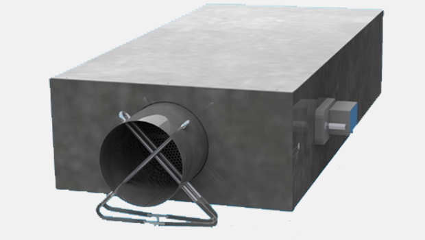
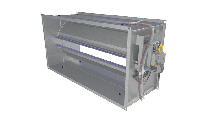
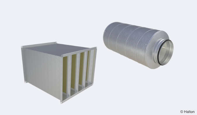
- Sound attenuator for noise reduction. Model with access panel available for easy maintenance.
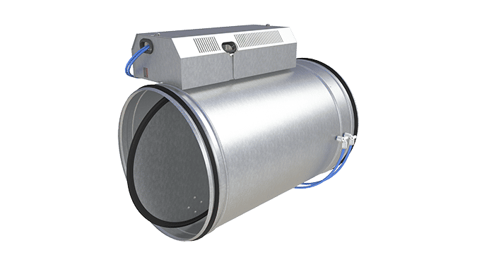
- Electric reheat coil with an internal heating controller. Power supply 230 VAC, less than 16A. A safety overheat thermostat with both automatic and manual reset, as well as an alarm relay with the possibility of remote alarm monitoring, are incorporated in the heater. A room controller is required to control the duct heater with a 0…10 VDC control signal.
- Electric reheat coil without an internal heating controller. Power supply 230 VAC. A safety overheat thermostat with both automatic and manual reset is incorporated in the heater. A room controller is required to control the duct heater with a 0…10 VDC control signal.
Installation
Installation options
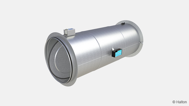
There are three possibilities to position the damper. Sensors can be directed outwards, side or inwards.
Safety distances and accuracy
Disturbances in the ductwork such as duct bends, T-branches and sound attenuators cause turbulence and an uneven airflow. This can lead to fluctuation and inaccuracy in measurement values.
Note: The recommended safety distance is longer or equal to three duct diameters’ distance, to ensure optimal accuracy.
Halton Max MUC technical performance:
- Velocity range 0,5 — 10,0 m/s
- General measurement uncertainty
- Accuracy ±5 %
- Minimum safety distances: Sizes 100-315 = 1D / Sizes 400-630 = 3D
- Expected measurement uncertainty, when correct installation parameter is applied ± % or l/s depending, which is the greatest of the percentage or the absolute value for the specific product size.
Dim. 100 = ±5 % or ±1,00 l/s
Dim. 125 = ±5 % or ±1,25 l/s
Dim. 160 = ±5 % or ±2,5 l/s
Dim. 200 = ±5 % or ±4,0 l/s
Dim. 250 = ±5 % or ±6,5 l/s
Dim. 315 = ±10 % or ±10 l/s
Dim. 400 = ±10 % or ±15 l/s
Dim. 500 = ±10 % or ±25 l/s
Dim. 630 = ±15 % or ±93 l/s *
Note: The measurement uncertainty is defined in laboratory conditions and may be greater in practical installations, where non-optimal installation situations or multiple consequent disturbances may exist.
* Dim. 630 velocity range 0.5 – 8.0 m/s
Wiring
The wiring must be carried out by professional technicians following local regulations. For the power supply, a safety-isolating transformer must be used.
The bus must be implemented according to standard EIA/TIA-485.
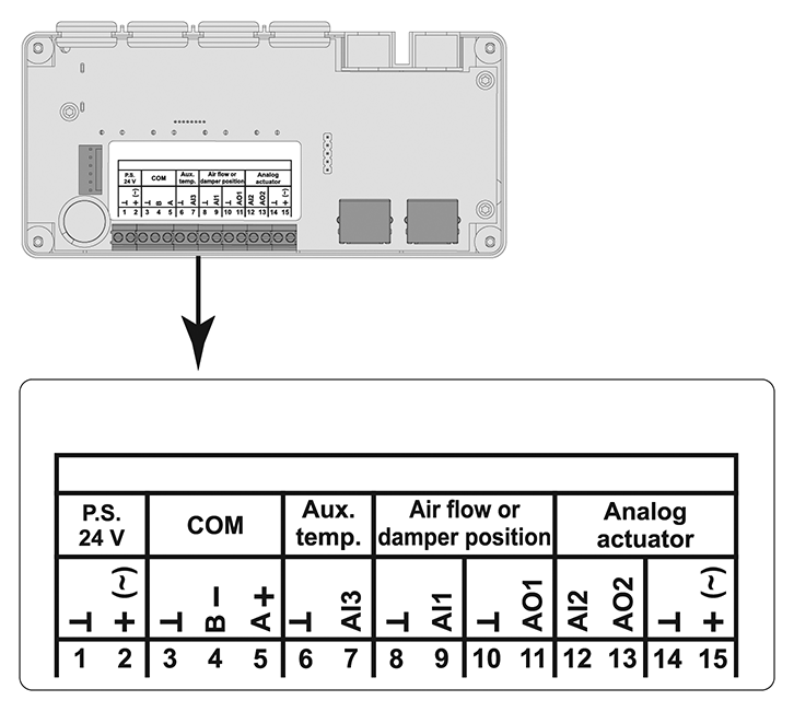
Controller connections
| Terminal | Name | Description |
| 1 | GND | Ground |
| 2 | 24 V DC/AC | Power supply input |
| 3 | GND | Ground |
| 4 | Standard RS-485 B | Data receive/send line B- |
| 5 | Standard RS-485 A | Data receive/send line A+ |
| 6 | GND | Ground |
| 7** | AI3 | Input for NTC 10k temperature sensor |
| 8 | GND | Ground |
| 9 | AI1 | Input for airflow or damper reference signal |
| 10 | GND | Ground |
| 11 | AO1 | Output for airflow or damper feedback signal |
| 12* | AI2 | Analogue actuator feedback signal |
| 13* | AO2 | Analogue actuator reference signal |
| 14* | GND | Ground |
| 15* | 24 V DC/AC | Power supply output for the analogue actuator |
* Connected to Siemens GDB 161.1E or Belimo LM24A-SR actuator
** Not included in delivery
Connection cable:
After 20.06.2024, delivered controller include 1 meter connection cable.
| Wire colour | Name | Description |
| 1 = black | GND, (AC G0, DC-) | Ground |
| 2 = red | 24 V (AC G, DC+) | Power supply input |
| 7 = grey | Modbus line A+ | Data receive/send line A+ |
| 6 = pink | Modbus line B- | Data receive/send line B- |
| 3 = white | AI1 | Input for airflow or damper reference signal |
| 5 = orange | AO1 | Output for airflow or damper reference signal |
Note: All cables that are not connected must be terminated.
Controller settings
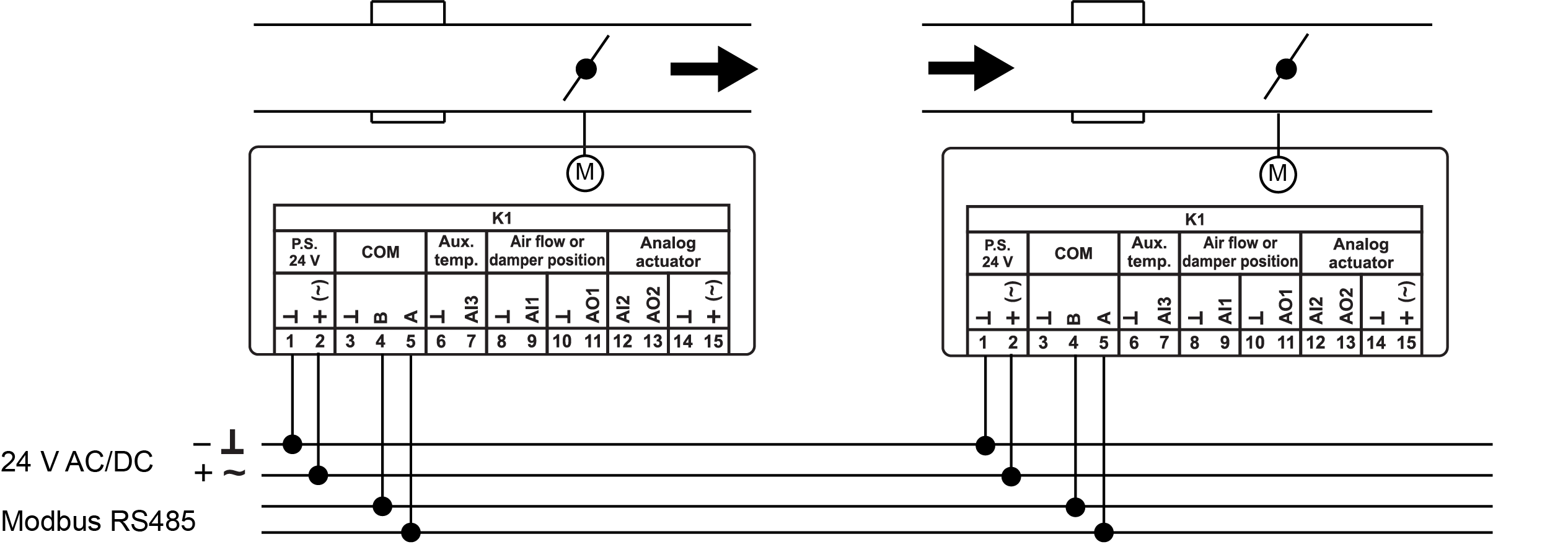
Fig.9. Wiring diagram: Modbus RTU commucation
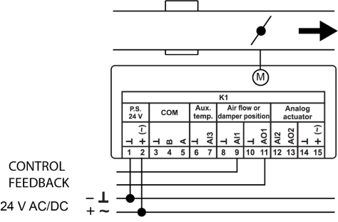
Fig.10. Wiring diagram: Analog control
Control scheme for Halton Max MUC with a master-slave configuration
In the following example, the supply unit is controlling the exhaust unit.
Control scheme for Halton Max Ultra Circular with a parallel configuration
Commissioning
Before the system start-up, the controller settings (including the correct installation case) and optionally the Modbus communication parameters have to be set.
Factory settings
The airflow range for Halton Max MUC is preset at the factory. The factory settings for the control signal and feedback signal are the same, but they can be configured individually. If the airflow range is not specified by the customer, the default factory settings are the following: The airflow rates for Halton Max MUC are preset at the factory. If the airflow rates are not specified by the customer, the default factory settings are:
- 0 l/s for the minimum airflow rate
- the maximum airflow rate corresponds to 10 m/s airflow velocity
The maximum airflow (Vnom) rates in the following table are given with an airflow velocity of 10 m/s.
| NS | Maximum airflow [l/s] @ 10 m/s | Maximum airflow [m3/h] @ 10 m/s |
| 100 | 79 | 283 |
| 125 | 123 | 441 |
| 160 | 201 | 723 |
| 200 | 314 | 1130 |
| 250 | 491 | 1767 |
| 315 | 779 | 2805 |
| 400 | 1257 | 4524 |
| 500 | 1963 | 7068 |
| 630 | 3117 | 11222 |
Table 1. Halton Max MUC factory settings
Note: Step-by-step instructions on how to perform the commissioning can be found in the Halton Max MUC Installation, commissioning and maintenance guide (see section Downloads).
Accessories
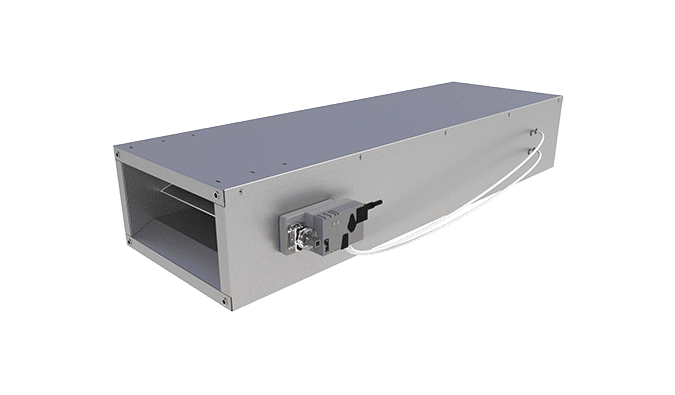
Sound attenuators
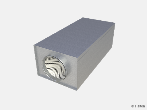
Description
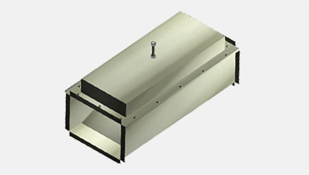
Halton offers high-quality rectangular sound attenuators with round duct connection for reducing noise levels in the duct. Sound attenuators are available as accessory and the following options are available:
- Three lengths: 600, 1000 and 1250 mm
- Connection types
- D2=D1
The duct (D2) and damper (D1) connections are the same size - D2>D1
The duct connection (D2) is one size larger than the damper (D1) connection
- D2=D1
- Insulation material options:
- Polyester fibre (PEF), tested according to ISO 7235, class C tightness level
- Mineral wool (MW), class C tightness level
- Available with or without access panel for maintanance purposes
Technical data
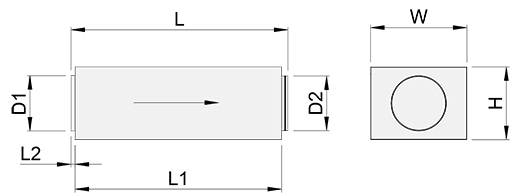
D1 is connected directly to the damper with female-type connection. D2 is attached to the duct with male-type connection. The above picture depicts supply air installations. In exhaust installations, the airflow direction is from D2 to D1. The damper is always connected to D1.
Dimensions (mm) and weights
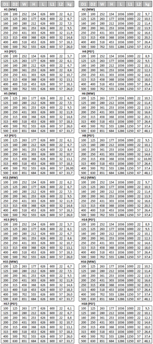
Fig.11. Sound attenuators dimensions and weight
Examples of attenuation data:
Attenuation data, L = 600 mm, material = PEF
Attenuation data, L = 1000 mm, material = PEF
Note: For further information, contact Halton Sales.
Reheat coils
Description
Reheat coils are available as accessory. Main features:
- Product models:
- Model RM
Without internal heating controller, PWM control signal input - Model RC
With internal heating controller, 0…10-VAC control signal input. Built-in alarm relay with potential-free changeover contact for remote alarm monitoring. The alarm is triggered by manual overheating protection or heater power loss.
- Model RM
- Sinlge-phase heater with 230 VAC, less than 16 A
- Increased heater safety with two internal overheating protection devices (automatic and manual), connected in series.
- EN 15727 class C tightness level
- Available for duct sizes 100 – 400 mm
- Power 600 – 3000 W
Technical data
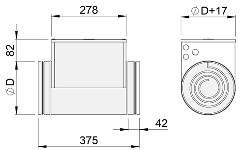
Fig.12. Reheat coil dimensions
Note: Reheat coil is not available for sizes over 400 mm
The heater can be installed in vertical or horizontal ducts. The safety distance is 2xD.
The heater must always be interlocked towards the fan or towards the airflow going through the heater. The interlocking function is connected to the duct heater power supply or, if the heater has an internal heating controller (model RC), it can also be connected directly to the controller.
The power supply to the duct heater must be switched off when the fan is switched off or when the airflow rate is too low.
When selecting the airflow control damper and reheat coil, ensure that the airflow velocity is above 2 m/s in order to guarantee a proper control function.
Heating capacity with low air velocity of 2 m/s
|
NS |
Power (W) |
qv l/s |
qv m3/h |
dT(max) K |
|
100 |
600 |
16 |
57 |
32 |
|
125 |
900 |
25 |
88 |
31 |
|
160 |
1500 |
40 |
145 |
31 |
|
200 |
2100 |
63 |
226 |
28 |
|
250 |
3000 |
98 |
353 |
25 |
|
315 |
3000 |
156 |
561 |
16 |
|
400 |
3000 |
251 |
905 |
10 |
Heating capacity with an air velocity of 6 m/s
|
NS |
Power (W) |
qv l/s |
m3/h |
dT(max) K |
|
100 |
600 |
47 |
170 |
11 |
|
125 |
900 |
74 |
265 |
10 |
|
160 |
1500 |
121 |
434 |
10 |
|
200 |
2100 |
188 |
679 |
9 |
|
250 |
3000 |
295 |
1060 |
8 |
|
315 |
3000 |
468 |
1683 |
5 |
|
400 |
3000 |
754 |
2714 |
3 |
Note: For further information, contact Halton Sales.
Order code
MUC/S-D, MA-CU-FS-SA-RH-ZT
S = Model
G With blade gasket
D = Size of duct connection [mm]
100, 125, 160, 200, 250, 315, 400, 500, 630
Other options and accessories
SP = System package
N No
Y Yes
MA = Material
GS Galvanised steel
AS Stainless steel (EN 14404/AISI 316L)
CU = Control unit
G2 GDB 161.1E, 5 Nm
G3 GLB 161.1E, 10 Nm
G4 LM24A-SR, 5 Nm
G5 NM24A-SR, 10 Nm
FS = Factory-set airflow limits
DS Default factory settings (Vnom)
DC Customer specified settings
SA = Sound attenuator
-> only available from Kausala, Finland
NA Not assigned
H1 L = 600 mm; Outlet = Inlet; Mineral wool
H2 L = 1000/1250 mm; Outlet = Inlet; Mineral wool
H3 L = 600 mm; Outlet = Inlet; Polyester fibre
H4 L = 1000/1250 mm; Outlet = Inlet; Polyester fibre
H5 L = 600 mm; Outlet > Inlet; Mineral wool
H6 L = 1000/1250 mm; Outlet > Inlet; Mineral wool
H7 L = 600 mm; Outlet > Inlet; Polyester fibre
H8 L = 1000/1250 mm; Outlet > Inlet; Polyester fibre
H11 L = 600 mm; Outlet = Inlet; Mineral wool; Access panel
H12 L = 1000/1250 mm; Outlet = Inlet; Mineral wool; Access panel
H13 L = 600 mm; Outlet = Inlet; Polyester fibre; Access panel
H14 L = 1000/1250 mm; Outlet = Inlet; Polyester fibre; Access panel
H15 L = 600 mm; Outlet > Inlet; Mineral wool; Access panel
H16 L = 1000/1250 mm; Outlet > Inlet; Mineral wool; Access panel
H17 L = 600 mm; Outlet > Inlet; Polyester fibre; Access panel
H18 L = 1000/1250 mm; Outlet > Inlet; Polyester fibre; Access panel
RH = Electric reheat coil
-> only available from Kausala, Finland
NA Not assigned
RM No internal heating controller, PWM control signal input (230 VAC, pulse width modulation)
RC With internal heating controller (0…10-VAC control signal input)
ZT = Tailored product
N No
Y Yes (ETO)
Code example
MUC/G-100, SP=N, MA=GS, CU=G2, FS=DC, SA=NA, RH=NA, ZT=N
Downloads
-
Halton Max MUC – Ultrasound airflow management damper (VAV)
Data
en
-
Halton Max MUC – Ultraääni ilmavirtasäädin (VAV)
Data
fi
-
Halton Max MUC – Ultraljud spjäll (VAV)
Data
se
-
Quick guide for commissioning – Halton Max MUC
Data
English (en) -
Asennus-, käyttöönotto- ja huolto-ohje – Halton Max MUC
Data
Suomi (fi) -
Guide för installation, driftsättning och underhåll – Halton Max MUC
Data
Svenska (sv) -
Halton Max Ultra Circular (MUC) and Halton Max One Circular (MOC) brochure
Data
English (en) -
Halton Max Ultra Circular (MUC) ja Halton Max One Circular (MOC) esite
Data
Finnish (fi) -
Halton Max Ultra Circular (MUC) et Halton Max One Circular (MOC) brochure
Data
French (fr) -
Installation, commissioning and maintenance guide – Halton Max MUC
Data
English (en)
"*" indicates required fields
ABD – Automated Balancing Damper for kitchen ventilation (CE)
product
ABD – Automatic balancing damper for kitchen ventilation (ETL)
product
CID-01 – Zero leakage isolation damper
product
Halton BOX – Airflow management unit (VAV)
product
Halton Max MDC – Zone control damper for Halton Workplace system
product
Halton Max MLC – Airflow management damper (VAV)
product
Halton Max MOC – Airflow management damper (VAV)
product
Halton Max MOS – Airflow management damper (VAV)
product
Halton Max MSB – Slim airflow management damper (VAV)
product
Halton Max MUC – Ultrasound airflow management damper (VAV)
product

Halton PRA – Airflow management damper (CAV)
product
Halton PTS – Airflow management damper (single-blade)
product
Halton RMC – Airflow management damper (CAV)
product
Halton SA – Sound attenuator
product
Halton UKV – Airflow management damper (VAV)
product
Halton UTK – Multi-blade airflow management damper (CAV)
product
Halton UTT – Multi-blade airflow management damper (CAV)
product

Halton Vita VLR – Room airflow controller for Halton Vita Lab solutions
product
Halton Vita VLS – Fume cupboard controller for Halton Vita Lab solutions
product
KBD – Exhaust hood balancing damper (ETL)
product