Product / VLS
Halton Vita VLS – Fume cupboard controller for Halton Vita Lab solutions
The Halton Vita VLS airflow controller operates as a fundamental element of the exhaust ductwork in the Halton Vita Lab solutions.
It controls the airflow of the fume cupboard and maintains the constant face velocity in the fume cupboard´s open sash.
- Designed for the ventilation control of fume cupboards in laboratories where safety, air quality and comfort need to be maintained at the required level regardless of external conditions
- Suitable for fume cupboards in research, production and educational laboratories
- Different types of material available depending on the requirements
- Energy efficient solution with versatile features
Overview
The Halton Vita VLS controller operates as a fundamental element of the exhaust ductwork in the Halton Vita Lab solutions. It controls the airflow of the fume cupboard and maintains the constant face velocity in the fume cupboard´s open sash.
The controller provides fast and accurate airflow control for all types of fume cupboards. It is
- Designed for the ventilation control of fume cupboards in laboratories where safety, air quality and comfort need to be maintained at the required level regardless of external conditions
- Suitable for fume cupboards in research, production and educational laboratories
- Different types of material available depending on the requirements
- Energy efficient solution with versatile features
Application
- Halton Vita Lab basic applications for normal laboratory conditions:
- Face velocity control – maintains a constant face velocity regardless of the sash position
- Dual position airflow control – maintains a minimum face velocity by detecting if the sash is open or closed
- Halton Vita Lab Pro meets the requirements for the most demanding laboratory spaces:
- Sash movement control – controls the sash movement to provide a quick increase of the exhaust airflow, while also controlling the sash position in order to maintain a constant face velocity
- Double sensor control – maintains the face velocity at a predefined level and controls the sash movement in order to provide an exceptionally quick increase of the exhaust airflow
Key features
- Stand-alone system
- Pressure-independent operation
- All types of fume cupboards
- Airflow is measured with cross measuring tubes, orifice plate or venturi (only plastic)
- Several materials available; galvanize, stainless steel and epoxy coated steel, PVC and PPS plastics
- Project specific settings are preset and tested at the factory
- Several connection sizes between 100-630 mm
- Velocity range 1 — 6.5 m/s
- Can be connected to Buildings Management System (BMS)
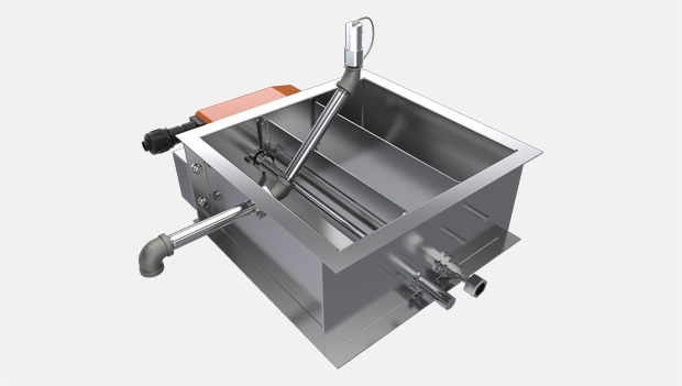
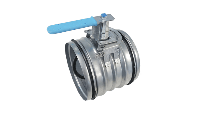
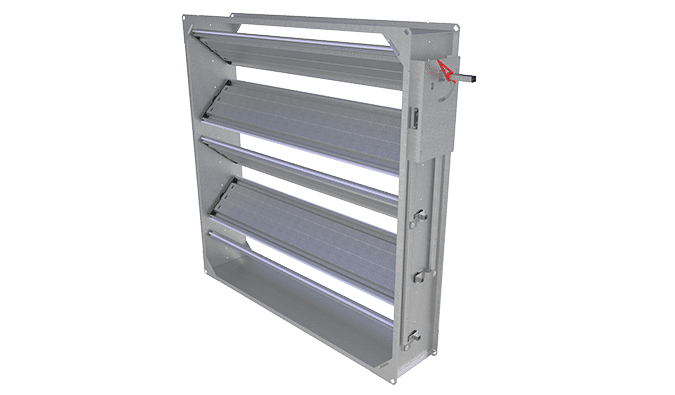
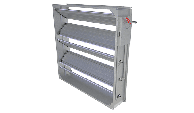
Operating principle
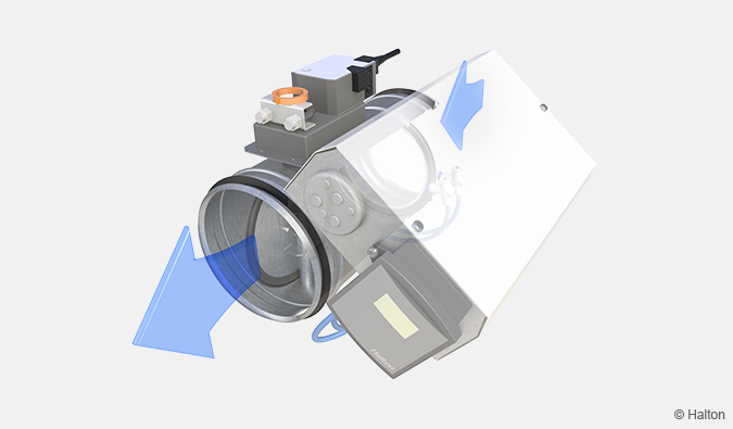
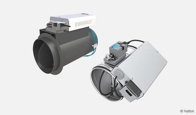
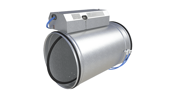
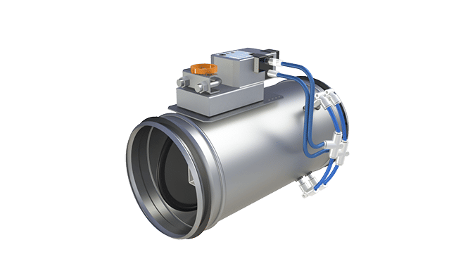
Fig.1. Operating principle of Halton Vita VLS with VFC damper
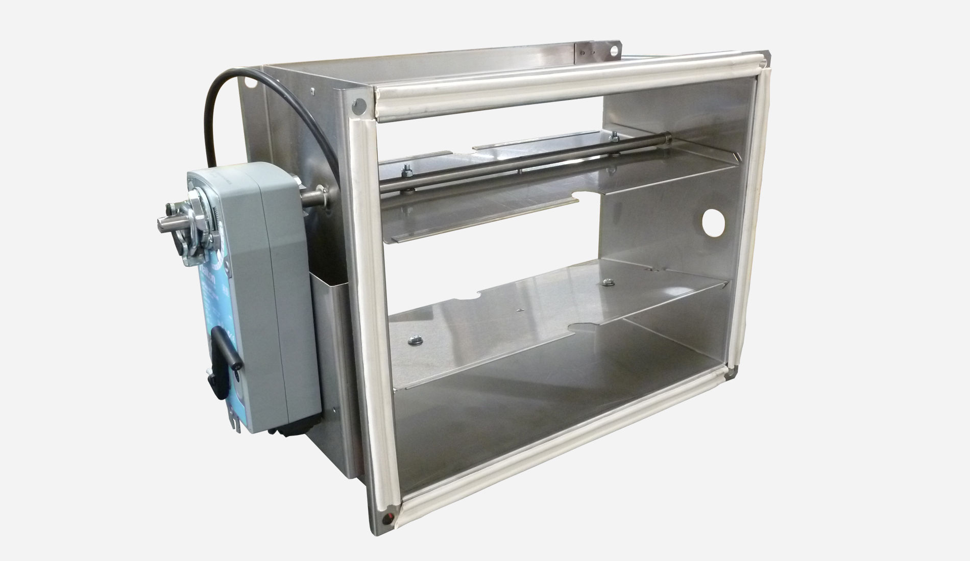
The Halton Vita VLS with VFC airflow damper contains an airflow measurement unit, a VAV airflow controller, a fast actuator, differential pressure sensor and a blade (with or without gasket).
The control signal and the airflow measurement data from the pickup tubes are processed in the Halton Vita VLS controller. The Halton Vita VLS controller gives the actuator a command to change the position of the damper blade, in order to keep the airflow at the predefined setpoint.
The damper controls the airflow of the fume cupboard or laminar cabinet. It maintains the required airflow through accurate measurement and airflow control. The most accurate control will be achieved when the ductwork has a constant static pressure, controlled by air handling unit and/or Halton Vita VLZ controller.
The airflow measurement is based on a differential pressure generated by high-precision pickup tubes of the measurement probe, orifice or venturi unit depending on the environment and the material requirements.
The user can adjust following settings manually from the control panel Halton HTP (if allowed):
- Damper control On/Off
- ECO or Max mode
- Light On/Off
All other settings are protected behind the password.
The ECO mode can be controlled also by occupancy sensor or from the building management system (BMS).
Key technical data
| Feature | Value |
| Duct connection sizes |
|
| Material |
|
| Air velocity range |
|
| Operating range (ambient temperature) | 0-50 ℃ |
| Ambient relative humidity (non-condensing) | < 95% |
| Communication interface | ModBUS RTU/IP, BACnet/IP |
Operating modes
|
|
| Accessories |
|
| Protection class |
|
| Power supply |
|
| Standards and certifications
|
|
| Maintenance | According to the building maintenance program |
Features and options
| Category | Name | Description |
| Control concept | Face velocity control | Constant face velocity control for fume cupboards with horisontal and vertical shases. |
| Dual position airflow control | Variable airflow control for fume cupboards with vertical shases. | |
| Sash position control | Constant face velocity control for fume cupboards with vertical shases. | |
| Sash movement control | Control of the sash position in order to maintain a constant face velocity for fume cupboards with vertical shase. | |
| Double sensor control | Control the face velocity in order to maintain the face velocity at its setpoint for fume cupboards with horisontal and vertical shases. | |
| Damper (Centralised control) |
VFH | Circular with gross tube, galvanised steel |
| VFC | Circular with orifice plate, galvanised steel | |
| VFA | Circular with orifice plate, antibacterial painted galvanised steel | |
| VFN | Circular with orifice plate, stainless steel (EN 14404/ AISI 316L) | |
| VFI | Circular with cross tube, stainless steel (EN 14404/ AISI 316L) | |
| VFP/Y | Circular with gross tube, plastic PVC or PPS | |
| VFP/V | Circular with venturi and flange connections
|
|
| Measurement unit (Single control) |
VVH | Circular with gross tube, galvanised steel |
| VVI | Circular with cross tube, stainless steel | |
| VVP | Circular with gross tube, plastic |
For more detailed information of the codes, see section Order code.
Solution description
Halton Vita VLS controller is a part of the Halton Vita Lab solution offering.
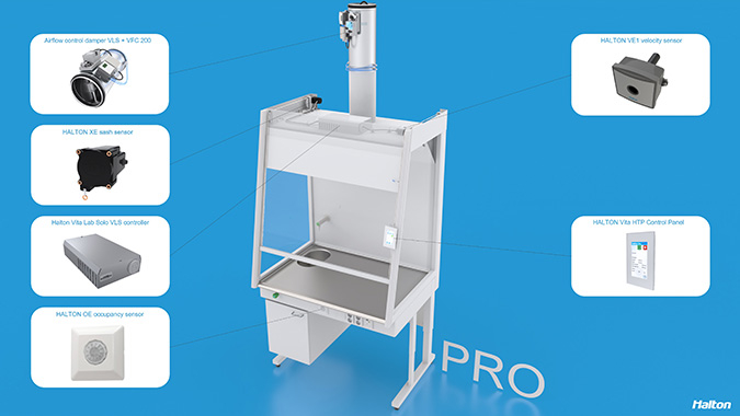
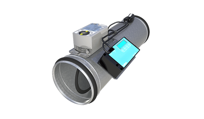
Fig.2. Halton Vita VLS controller+VFC airflow damper combined with a Halton Vita Lab Solo controller, Halton Vita VSS sensor package (sash and velocity sensors) and Halton HTP touch panel
Halton Vita VLS is a controller designed for controlling the fume cupboards or laminar cabinets in a laboratory and cleanroom environment. It is used for controlling the ventilation airflow according to the EN standard EN 14175-6.
This controller package consists of a controller unit and optional components depending on customer needs: a control panel and sensors for controlling the face velocity (velocity and sash sensor) and occupancy.
In the laboratory room Halton fume cupboard ventilation controllers Halton Vita VLS are connected to the Halton Vita VLR (room controller) via internal BUS. The holistic system includes all components for high required laboratory ventilation control.
Application area
- Controlling the ventilation airflow of the fume cupboards and laminar cabinets according to the EN 14175-6
- The Halton Vita VLS controller is a part of Halton Vita Lab solution. This controller communicates with Halton Vita VLR controller, which controls the room airflow, pressure, temperature and CO2 level
- Overall Halton Vita Lab systems includes:
- Halton Vita Lab Room air conditioning applications
- Supply airflow
- General exhaust
- Room pressure
- Temperature and CO2
- Halton Vita Lab Solo fume cupboard control
- Face velocity control
- Dual position airflow control
- Sash position control
- Sash movement control
- Double sensor control
- Halton Vita Lab Zone duct static pressure
- Zone pressure control
- Local exhaust units and all ventilated components in the laboratory environment
- Halton Vita Lab Room air conditioning applications
Key features
- Fast and accurate control
- User safety
- Factory-tested controller and wiring, easy to install
- Pre-installed project-specific parameters, quick to commission
- Versatile system which can be installed in any type of fume cupboards
- Highly energy-efficient and reliable system operation
- Can be connected to the Halton remote system
Operating principle
Fume cupboard ventilation control
Fume cupboard controller is located in fume exhaust VAV damper (Halton Vita VLS). Fume cupboard airflows are controlled to maintain flow rate that is in accordance with defined face velocity (default 0,5m/s). Velocity sensor is installed on the fume cupboard and this measurement is used as feedback signal for the airflow control. Sash sensor is installed on the fume cupboard (sash counter-weight) and this measurement is used as feedback signal for accelerated control when sash position is changing
Operation of the fume cupboard can be monitored from the local control panel (Halton HTP), which is installed on the fume cupboard. At the front page it displays the measured airflow and setpoint + alarm values. It also indicates alarms and allows user to change operational parameters. Optionally, user can select the fume cupboard ventilation mode on the control panel (Eco/Normal/Max -modes).
ECO -mode
The ECO mode saves energy and capacity by setting the face velocity setpoint in the minimum position, e.g. from 0,5m/s to 0,3m/s. The manual ECO mode allows the user to activate it from the Halton HTP touch panel. The feature is enabled and adjusted from the configuration menu. The automatic ECO mode is an optional feature and requires an occupancy sensor. It provides further savings in energy usage by automatically activating the ECO mode when there is no presence in front the fume cupboard. The set value is pre-configured from the Halton HTP configuration menu.
Flow watch
The flow watch is an optional feature and requires an occupancy sensor. When there is no presence in the front of the fume cupboard and the sash is open more than minimum opening, an acoustic alarm appears on the Halton HTP panel.
The idea is to inform users an open sash.
Energy consumption calculation
The energy consumption calculation is an optional feature. The purpose of the energy consumption calculation is to modify user behaviour towards more energy-efficient system performance by steering them towards keeping the sash in minimum position as much as possible. Simultaneously, the control function makes working in the laboratory safer for users as fumes are least likely to escape the fume cupboard when the sash is in the minimum position. When the capacity of the air handling unit is often in a limit, to avoid the capacity issues….
The control principle is based on airflow measurement every one minute. The average performance is calculated for one week at a time. The weekly result is displayed on the Halton HTP panel and give an energy rate, from deep green leaf red leaf. Yellow leaf is the level of regularly working in the fume cupboard for 8h every working day, five days a week. Improvements from this level lead to better letters and energy ratings.

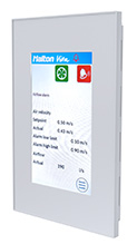
Fig.3. Halton HTP Basic and Pro control panels

Quick selection
Halton Vita VLS with VFC and VFN damper
| NS [mm] |
l/s min @ 0.5 m/s |
l/s max @ 6 m/s |
m3/h min @ 0.5 m/s |
m3/h max @ 6 m/s |
| 125 | 6,9 | 74.0 | 24.8 | 266.0 |
| 160 | 10.0 | 121.0 | 36.0 | 434.0 |
| 200 | 15.9 | 188.4 | 56.5 | 678.0 |
| 250 | 25.0 | 294.4 | 90.0 | 1060.0 |
| 315 | 39.0 | 468.0 | 140.0 | 1683.0 |
| 400 | 63.0 | 754.0 | 226.0 | 2714.0 |
| 500 | 98.0 | 1178.0 | 353.0 | 4241.0 |
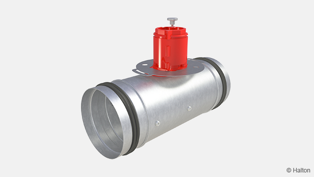
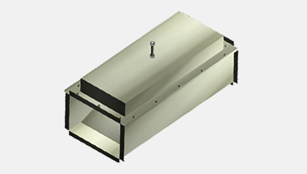
Structure and materials
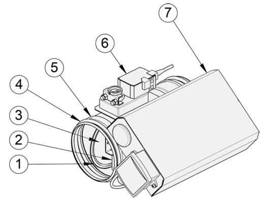
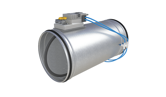
Fig.3. Halton Vita VLS with damper VFC
| No. | Part | Material | Note |
| 1 | Blade gasket | EPDM rybber | – |
| 2 | Shaft | Galvanised steel | Stainless steel (EN 14404/AISI 316L) with damper option VFI |
| 3 | Blade | Galvanised steel | Stainless steel (EN 14404/AISI 316L) with damper option VFI |
| 4 | Duct seal gasket | 1C-polyurethane hybrid | – |
| 5 | Casing | Galvanised steel | Stainless steel (EN 14404/AISI 316L) with damper option VFI |
| 6 | Actuator | Plastic, steel, PVC cable | – |
| 7 | Airflow controller box | – | – |
Dimensions and weight
Halton Vita VLS controller with damper VFC, without insulation
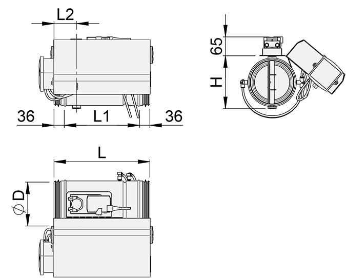
| NS [mm] |
⌀D [mm] |
L [mm] |
L1 [mm] |
L2 [mm] |
H [mm] |
Weight [kg] *) |
| 125 | 124 | 328 | 256 | 77 | 135 | 1.9 |
| 160 | 159 | 328 | 256 | 77 | 170 | 2.2 |
| 200 | 199 | 328 | 256 | 77 | 210 | 2.6 |
| 250 | 249 | 328 | 256 | 77 | 260 | 3.2 |
| 315 | 314 | 495 | 423 | 77 | 325 | 3.8 |
| 400 | 399 | 495 | 423 | 80 | 410 | 5.3 |
| 500 | 499 | 620 | 548 | 149 | 508 | 13.7 |
*) Without airflow control box
Specification
Pressure-independent variable airflow control damper for supply and exhaust installations, fulfilling the following requirements:
Construction
- Airflow is adjusted by the position of the blade and measuring is based on differential pressure over the cross tube or orifice plate
- Damper includes components
- Fast actuator, 2.5/4.0 s running time
- Controller box (“Master”) or junction box (“Slave”)
- Pressure transmitter
- Airflow measuring tubing
- Duct connection with integral airtight rubber gaskets
- Complete shut-off function (blade gasket), complies with EN 1751 class 4
- Plastic models complies with EN 1751 class 3
- Casing tightness complies with EN 1751 class C
- Damper with external insulation include a 50mm mineral wool
Material
- Galvanised steel
- Stainless steel (EN 14404/ AISI 316L)
- Plastic (PVC or PPS)
Electrical data
Master
- Supply voltage: 230 VAC (230 VAC / 24 VAC -transformer included)
- Actuators / sensors supply voltage: 24 VAC
- Analog control: 2…10 VDC
- Analog measuring: 0…10 VDC (0-200 Pa)
- Modbus RTU, Modbus TCP, Bacnet IP -communication available via controller
Slave:
- Supply voltage 24 VAC
- Actuators / sensors supply voltage: 24 VAC
- Analog control: 2…10 VDC
- Analog measuring: 0…10 VDC (0-200 Pa)
- No bus communication
Parameter settings
Master
- Design parameters are calibrated at the factory. Halton service will verify all parameters during commissioning phase.
- Dampers are tested at the factory.
- Controller settings are adjustable with a PC- or a handheld tool
Order code
VLS/C-O-T-D; IN-MA-FL-FC-TF-CB-LO-BB-SC-ZT
| Main options | |
| C = Control concept | |
| A | Face velocity control |
| B | Dual position airflow control |
| C | Sash position control |
| D | Sash movement control |
| E | Double sensor control |
| O = Control type | |
| S | Single |
| C | Centralised |
| T = Damper/measurement unit type | |
| A | VFH (galvanised steel, cross tube) |
| B | VFC (galvanised steel, orifice) |
| C | VFA (galvanised steel, orifice, antibacterial) |
| D | VFN (stainless steel, orifice) |
| E | VFI (stainless steel, cross tube) |
| F | VFP/Y (measurement unit, galvanised steel, cross tube) |
| G | VFP/V (measurement unit, stainless steel, cross tube) |
| H | VVH (measurement unit, galvanised steel, cross tube) |
| I | VVI (measurement unit, stainless steel, cross tube) |
| J | VVP (measurement unit, plastic, cross tube) |
| D = Duct connection size [mm] | 100, 125, 160, 200, 250, 315, 400, 500 |
| Other options and accessories | |
| IN = Insulation | |
| I3 | Insulated, 50 mm |
| NA | Not assigned |
| MA = Material | |
| CS | Hot-galvanised steel |
| AS | Stainless steel (AISI 316) |
| PP | PPS |
| PV | PVC |
| FL = Flanges (for VFP, plastic damper) | |
| Y | Yes |
| N | No |
| FC = Controller | |
| A1 | VLC-A1 (Modbus, 2 port, 15 I/O) |
| A2 | VLC-A2 (Modbus, 3 port, 28 I/O) |
| TF = Transformer | |
| TF1 | 230/24 transformer (35VA) |
| N | No |
| CB = Control box | |
| CB1 | Galvanised box, delivered attached to damper/measurement unit |
| CB2 | Galvanised box, delivered separately from damper/measurement unit |
| NA | Not assigned |
| LO = Light control option | |
| Y | Yes |
| N | No |
| BB = Battery back-up unit | |
| NA | Not assigned |
| SC = Automatic sash control | |
| N | No |
| ZT = Tailored product | |
| N | No |
| Y | Yes (ETO) |
| Sub products and accessories (ordered separately) |
|
| Halton Vita VSS | Sensor package |
| Halton Vita HTP | Control panel |
Order code example
VLS/A-C-A-160; IN=NA; MA=CS, FL=N, FC=A1, TF=TF1, CB=CB1, LO=Y, BB=NA, SC=N, ZT=N
Installation
Wiring
The wiring must be carried out by professional technicians in accordance with local regulations. For the power supply, a safety-isolating transformer must be used.
Installation instructions and project-specific wiring diagrams are provided by Halton for all Halton Vita Lab Solo system configurations.
For more information, see the Halton Vita Lab Solo Design guide available from Halton Sales.
Downloads
-
Halton Vita Laboratory Solutions
Data
DK -
Halton Vita Solutions Laboratoires
Data
Français (fr) -
Halton Vita Lab Solo Design Guide
Data
FI -
Halton Vita Laboratorio-ratkaisut
Data
Suomi (fi) -
Halton Vita Laboratory Solutions
Data
English (en) -
Halton Vita Lab Solo Design Guide
Data
GB -
Halton Vita lösningar för laboratorier
Data
Svenska (sv)
"*" indicates required fields
ABD – Automated Balancing Damper for kitchen ventilation (CE)
product
ABD – Automatic balancing damper for kitchen ventilation (ETL)
product
CID-01 – Zero leakage isolation damper
product
Halton BOX – Airflow management unit (VAV)
product
Halton Max MDC – Zone control damper for Halton Workplace system
product
Halton Max MLC – Airflow management damper (VAV)
product
Halton Max MOC – Airflow management damper (VAV)
product
Halton Max MOS – Airflow management damper (VAV)
product
Halton Max MSB – Slim airflow management damper (VAV)
product
Halton Max MUC – Ultrasound airflow management damper (VAV)
product

Halton PRA – Airflow management damper (CAV)
product
Halton PTS – Airflow management damper (single-blade)
product
Halton RMC – Airflow management damper (CAV)
product
Halton SA – Sound attenuator
product
Halton UKV – Airflow management damper (VAV)
product
Halton UTK – Multi-blade airflow management damper (CAV)
product
Halton UTT – Multi-blade airflow management damper (CAV)
product

Halton Vita VLR – Room airflow controller for Halton Vita Lab solutions
product
Halton Vita VLS – Fume cupboard controller for Halton Vita Lab solutions
product
KBD – Exhaust hood balancing damper (ETL)
product