
Product / RMK
Halton RMK – Airflow management damper (CAV)
The Halton RMK is a high performance, mechanically actuated CAV airflow management damper designed to deliver reliable, energy efficient, and pressure independent airflow management.
It ensures precise ventilation across even the most complex duct systems. It maintains a consistent, independent airflow rate for both supply and exhaust applications, regardless of fluctuations in duct static pressure. It supports sustainability goals by optimising ventilation efficiency, minimising commissioning effort, and reducing ongoing energy consumption.
- Constant airflow damper without external power supply, self-balancing operation
- Optimised volume flow control unit
- Model with peripheral acoustic insulation (RMK/I).
- For high airflow rates, it is available in a Twin version (dual‑blade design).

Overview
The Halton RMK is a mechanical airflow controller designed to maintain a constant airflow rate in terminal or secondary ducts, independent of system pressure variations. This makes it suitable for demanding CAV applications.
The dual blade design ensures stable regulation, accurate performance, and low noise levels across the operating range. Fully mechanical operation eliminates the need for an external power supply, improving reliability and simplifying installation. Durable metal construction supports a long service life, while energy efficient airflow control reduces fan energy usage.
Application areas
- Commercial buildings
- Healthcare facilities
- Industrial and technical facilities
Key features
- On/off or proportional actuation available on request.
- For high airflow rates, the Halton RMK is available in a Twin version (dual‑blade design).
- Model with external insulation is available as an option
- Sound attenuator (accessory)
- Coil casing (accessory)
Operating principle
The regulation is based on variations in dynamic pressure caused by changes in upstream static pressure. Changes in dynamic pressure act on the airflow controller, which moves a damper blade balanced by a calibrated spring. By continuously adjusting the effective air passage cross-section, the blade modifies the pressure drop across the device to compensate for pressure variations and maintain a constant airflow rate. An integrated damping mechanism stabilises the blade movement and prevents oscillation until the equilibrium position is reached.
Halton RMK operates as a fully self‑regulating unit, requiring no external power supply and maintaining airflow independent of upstream pressure. Airflow is controlled by an adjustable, factory‑calibrated spring. The setpoint within the regulation range can be modified by changing the spring compression.
The airflow can be adjusted directly on site by tightening the adjustment screw according to the flow scale indicated on the adjustment cylinder.
Operating range
The constant airflow damper operates from a minimum pressure difference over the unit, which depends on the air velocity to a maximum of 1000 Pa.
Halton RMK
| Size | qv min. | qv max | qv min. | qv max | v min. | v max | dpst min. | dpst max |
|---|---|---|---|---|---|---|---|---|
| [mm] | [m3h] | [m3h] | [l/s] | [l/s] | [m/s] | [m/s] | [Pa] | [Pa] |
| 150 x 150 | 243 | 729 | 67.5 | 202.5 | 32 | 9 | 50 | 1000 |
| 300 x 100 | 216 | 799 | 60 | 222 | 2.0 | 7.4 | 50 | 1000 |
| 300 x 150 | 486 | 1458 | 135 | 405 | 3 | 9 | 50 | 1000 |
| 200 x 200 | 432 | 1296 | 120 | 360 | 3 | 9 | 50 | 1000 |
| 300 x 200 | 648 | 1944 | 180 | 540 | 3 | 9 | 50 | 1000 |
| 400 x 100 | 302 | 1094 | 84 | 304 | 2.1 | 7.6 | 50 | 1000 |
| 400 x 200 | 864 | 2592 | 240 | 720 | 3 | 9 | 50 | 1000 |
| 300 x 300 | 972 | 2916 | 270 | 810 | 3 | 9 | 50 | 1000 |
| 450 x 300 | 1458 | 4374 | 405 | 1215 | 3 | 9 | 50 | 1000 |
| 600 x 300 | 1944 | 5832 | 540 | 1620 | 3 | 9 | 50 | 1000 |
Halton RMK, Twin
| Size | qv min. | qv max | qv min. | qv max | v min. | v max | dpst min. | dpst max |
|---|---|---|---|---|---|---|---|---|
| [mm] | [m3h] | [m3h] | [l/s] | [l/s] | [m/s] | [m/s] | [Pa] | [Pa] |
| 400 x 400 | 1728 | 5184 | 480 | 1440 | 3 | 9 | 50 | 1000 |
| 500 x 400 | 2160 | 6480 | 600 | 1800 | 3 | 9 | 50 | 1000 |
| 600 x 400 | 2592 | 7776 | 720 | 2160 | 3 | 9 | 50 | 1000 |
| 500 x 500 | 2700 | 8100 | 750 | 2250 | 3 | 9 | 50 | 1000 |
| 600 x 500 | 3240 | 9720 | 900 | 2700 | 3 | 9 | 50 | 1000 |
| 600 x 600 | 3888 | 11664 | 1080 | 3240 | 3 | 9 | 50 | 1000 |
Structure and materials

| No. | Part | Material | Note |
|---|---|---|---|
| 1 | Casing | Galvanised steel | – |
| 2 | Adjustment tube | Plastic | – |
| 3 | Damper blade bearings | PTFE | – |
| 4 | Damper blade | Aluminium | – |
Dimensions
Halton RMK, dimensions

| Size [mm] | RMK | RMK/I* | P [mm] | ||
|---|---|---|---|---|---|
| L [mm] | H [mm] | L [mm] | H [mm] | ||
| 150 x 150 | 150 | 150 | 210 | 210 | 220 |
| 300 x 100 | 300 | 100 | 360 | 160 | 220 |
| 300 x 150 | 300 | 100 | 360 | 160 | 220 |
| 200 x 200 | 200 | 200 | 260 | 260 | 220 |
| 300 x 200 | 300 | 200 | 360 | 260 | 220 |
| 400 x 100 | 400 | 100 | 460 | 260 | 220 |
| 400 x 200 | 400 | 200 | 460 | 160 | 220 |
| 300 x 300 | 300 | 300 | 360 | 360 | 385 |
| 450 x 300 | 450 | 300 | 510 | 360 | 385 |
| 600 x 300 | 600 | 300 | 660 | 360 | 385 |
* Insulated (30 mm)
Halton RMK twin dimensions

| Size [mm] | L1 [mm] | H1 [mm] | P [mm] |
|---|---|---|---|
| 400 x 400 | 400 | 400 | 385 |
| 500 x 400 | 500 | 400 | 385 |
| 600 x 400 | 500 | 400 | 385 |
| 500 x 500 | 500 | 500 | 385 |
| 600 x 500 | 600 | 500 | 385 |
| 600 x 600 | 600 | 600 | 385 |
Product models
| Product model | Code | Description |
|---|---|---|
| Standard | N | Without insulation |
| Insulation | I | Mineral wool, thickness 30 mm, for sound insulation and reduction of heat transfer |
Specification
Rectangular mechanical constant airflow damper (CAV) with self- balancing operation for supply and exhaust installations, fullfilling the following requirements:
Function
- The constant airflow damper operates without an external electrical or pneumatic.
- The damper operates with an adjustable spring.
- No external electrical or pneumatic control required.
- The factory-set airflow can be adjusted on site.
- The maximum air temperature is 100 °C.
- The pressure range is 50–1000 Pa.
Materials
- The damper casing is made of galvanised steel.
- The damper blade and adjustment device are made of aluminium.
- The bearings are low-friction PTFE (Teflon).
- The damper casing is insulated with mineral wool as sound and thermal insulation material (optional).
Structure
-
Sizes from 150 x 150 to 600 x 600
Installation
The rectangular airflow management damper (CAV) is installed directly into the duct system. The damper can be installed on both horizontal and vertical ducts. However, when installed in vertical ducts, the adjustable spring must be positioned horizontally.
Follow the indicated airflow direction on the damper casing. The damper suits both supply and extract air ducts. Provide sufficient straight duct lengths upstream and downstream to ensure stable airflow control.
Safety distances for the damper
The airflow control damper should be installed in an undisturbed airflow. The airflow velocity profile in the duct should be sufficiently even, without disturbances from bends, T-branches, etc.
The required safety distance after a bend (90º elbow) or T-branch is 2.5 times the duct cross section diagonal (2.5 Diagonal). The damper should be installed so that the arrow points in the direction of the airflow. See the installation examples below.

Commissioning
The damper is factory set or can be adjusted on site to the required constant airflow value using the integrated mechanical adjustment device. Commissioning is performed without an external power supply. The airflow can be adjusted on site by tightening the adjustment screw, in accordance with the flow scale indicated on the adjustment cylinder.
Once set, the damper automatically maintains the specified airflow rate within its operating pressure range, eliminating the need for system balancing. Effective commissioning is achieved by reading and verifying the airflow setting on the built in scale.
Maintenance
All components are designed to be maintenance‑free, non‑ageing, and corrosion‑resistant under normal operating conditions. Routine functional checks are generally unnecessary. However, accessibility for inspection and commissioning must be ensured in accordance with the standard DIN EN 12097, which specifies access requirements for ventilation duct systems.
In standard applications, no further maintenance actions are required beyond ensuring that installation conditions and airflow profiles remain within the specified operating parameters.
Downloads
"*" indicates required fields
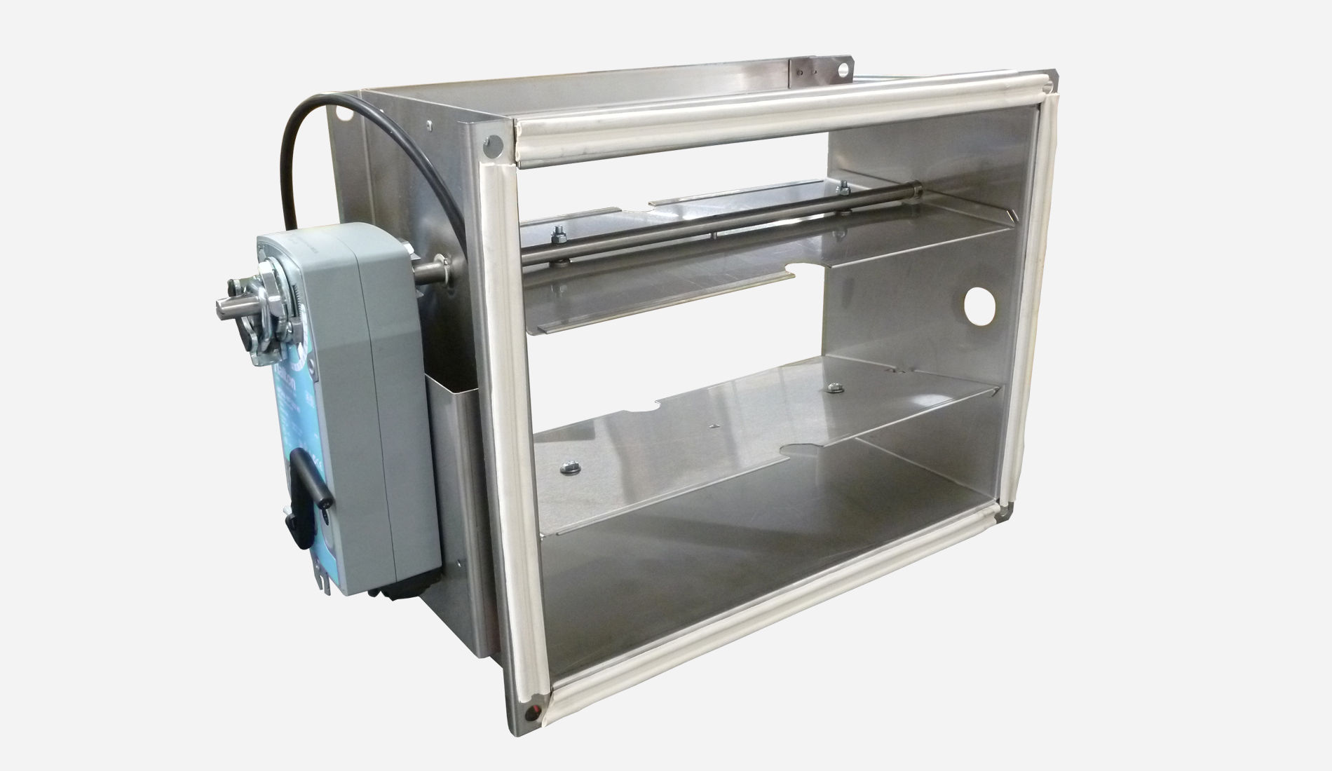
ABD – Automated Balancing Damper for kitchen ventilation (CE)
product
ABD – Automatic balancing damper for kitchen ventilation (ETL)
product

CID-01 – Zero leakage isolation damper
product
Halton BOX – Airflow management unit (VAV)
product
Halton Max MDC – Zone control damper for Halton Workplace system
product
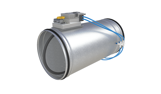
Halton Max MLC – Airflow management damper (VAV)
product
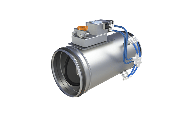
Halton Max MOC – Airflow management damper (VAV)
product
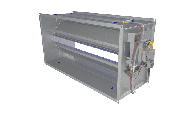
Halton Max MOS – Airflow management damper (VAV)
product
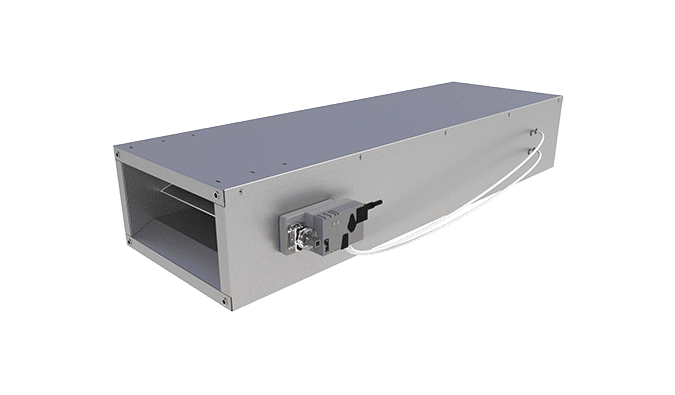
Halton Max MSB – Slim airflow management damper (VAV)
product
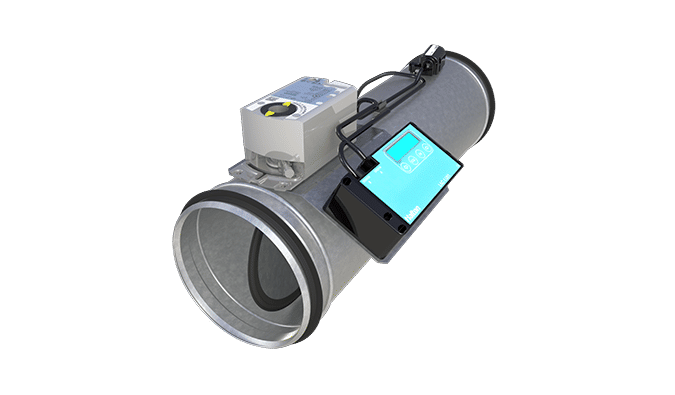
Halton Max MUC – Ultrasound airflow management damper (VAV)
product

Halton PRA – Airflow management damper (CAV)
product
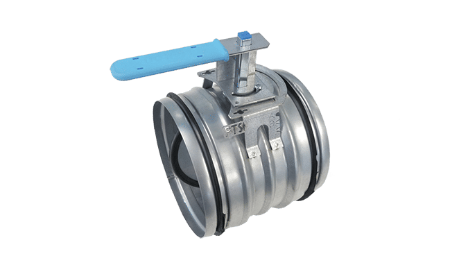
Halton PTS – Airflow management damper (single-blade)
product

Halton RDR – Adjustable airflow regulator
product
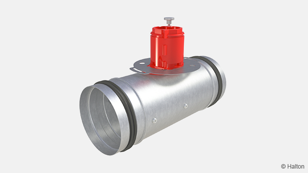
Halton RMC – Airflow management damper (CAV)
product
Halton RMK – Airflow management damper (CAV)
product
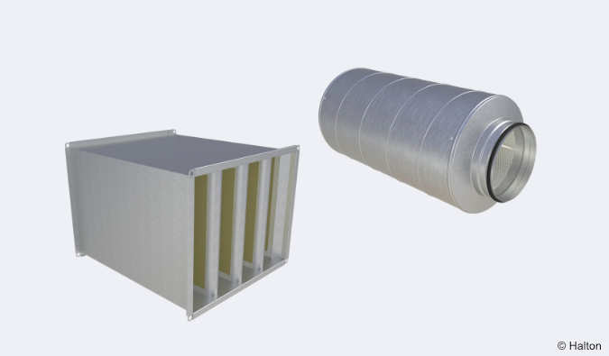
Halton SA – Sound attenuator
product
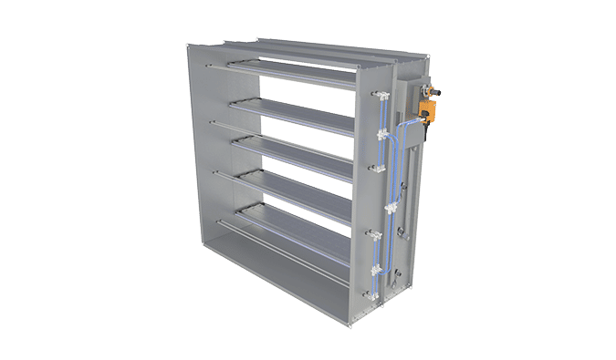
Halton UKV – Airflow management damper (VAV)
product
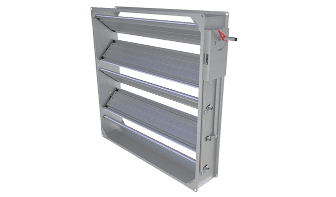
Halton UTK – Multi-blade airflow management damper (CAV)
product
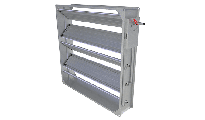
Halton UTT – Multi-blade airflow management damper (CAV)
product

Halton Vita VLR – Room airflow controller for Halton Vita Lab solutions
product