Product / SLM
Halton SLM – Linear slot diffuser
Larger slot diffuser for high airflow. This diffuser cab be used for ceiling or wall installation
- The product can handle big air flow rates with low noise level
- Ceiling or wall installation, suitable also for continuous “wall to wall” installations
Overview
- Horisontal or vertical plane jet air supply
- Suitable for supply and exhaust
- Special profile diffuser blade creates a Coanda effect which enables wide range or airflow rates
- Supply in one or two directions
- The product can handle high airflow rates with low noise level
- Ceiling or wall installation, suitable also for continuous “wall to wall” installations
- Adjustable throw pattern, flexibility of orientation with different configurations
- Detachable diffuser allows cleaning of the terminal unit and ductwork
Accessories
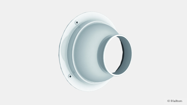
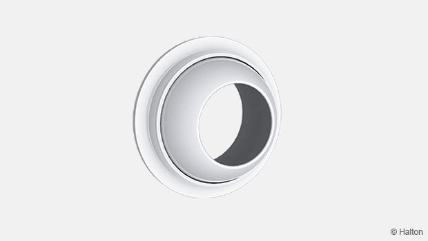
- Plenum with a circular duct connection(s) D160…250mm with rubber gasket
- Plenum options with measurement and adjustment functions
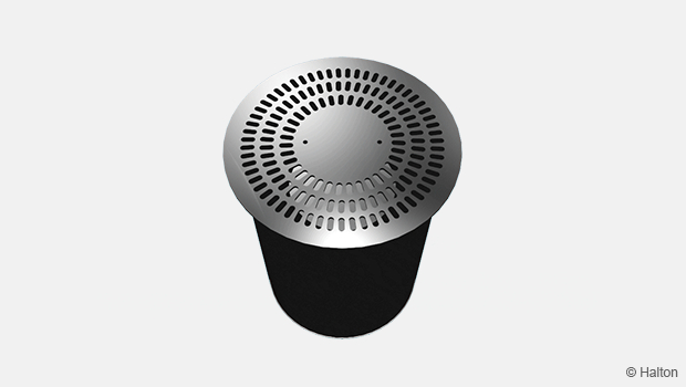
- Sound attenuation for plenum
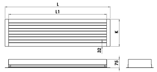
Dimensions
Halton SLM
 ‘
‘
Halton SLM + Halton PLM
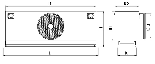
Standard dimensions of the Halton SLM + Halton PLM are presented in the table below :
| Active length |
Slots | F | L | L1 | H | H1 | K | K1 | K2 | ØD |
| 572 | 1 | 64 | 636 | 572 | 275..295 | 200 | 90 | 59 | 130 | 1×160 |
| 872 | 1 | 64 | 936 | 872 | 275..295 | 200 | 90 | 59 | 130 | 1×160 |
| 1172 | 1 | 64 | 1236 | 1172 | 275..295 | 200 | 90 | 59 | 130 | 1×160 |
| 1472 | 1 | 64 | 1536 | 1472 | 275..295 | 200 | 90 | 59 | 130 | 2×160 |
| 1772 | 1 | 64 | 1836 | 1772 | 275..295 | 200 | 90 | 59 | 130 | 2×160 |
| 572 | 2 | 114 | 636 | 572 | 315..335 | 240 | 141 | 109 | 181 | 1×200 |
| 872 | 2 | 114 | 936 | 872 | 315..335 | 240 | 141 | 109 | 181 | 1×200 |
| 1172 | 2 | 114 | 1236 | 1172 | 315..335 | 240 | 141 | 109 | 181 | 1×200 |
| 1472 | 2 | 114 | 1536 | 1472 | 315..335 | 240 | 141 | 109 | 181 | 2×200 |
| 1772 | 2 | 114 | 1836 | 1772 | 315..335 | 240 | 141 | 109 | 181 | 2×200 |
| 572 | 3 | 165 | 636 | 572 | 365..385 | 290 | 192 | 160 | 232 | 1×200 |
| 872 | 3 | 165 | 936 | 872 | 365..385 | 290 | 192 | 160 | 232 | 1×200 |
| 1172 | 3 | 165 | 1236 | 1172 | 365..385 | 290 | 192 | 160 | 232 | 1×200 |
| 1472 | 3 | 165 | 1536 | 1472 | 365..385 | 290 | 192 | 160 | 232 | 2×200 |
| 1772 | 3 | 165 | 1836 | 1772 | 365..385 | 290 | 192 | 160 | 232 | 2×200 |
| 572 | 4 | 216 | 636 | 572 | 365..385 | 290 | 243 | 211 | 283 | 1×250 |
| 872 | 4 | 216 | 936 | 872 | 365..385 | 290 | 243 | 211 | 283 | 1×250 |
| 1172 | 4 | 216 | 1236 | 1172 | 365..385 | 290 | 243 | 211 | 283 | 1×250 |
| 1472 | 4 | 216 | 1536 | 1472 | 365..385 | 290 | 243 | 211 | 283 | 2×250 |
| 1772 | 4 | 216 | 1836 | 1772 | 365..385 | 290 | 243 | 211 | 283 | 2×250 |
Installation hole for the ceiling: F x (L1+10)
Material
| Part | Material | Finishing | Note |
| Outer frame | Aluminium | Mill finished or Epoxy-painted, White (RAL 9003 / 30% gloss) |
Special colours available. Epoxy/Polyester painted as option |
| End caps / T profiles |
Aluminium | Mill finished or Epoxy-painted, white (RAL 9003 / 30% gloss) |
Special colours available. Epoxy/Polyester painted as option |
| Inner vanes | Aluminium | Mill finished or Epoxy-painted, white (RAL 9003 / 30% gloss) |
Special colours available. Epoxy/Polyester painted as option |
| Flow deflection vanes (for supply application) |
Aluminium | Mill finished | Special colours available. Epoxy/Polyester painted as option |
| Plenum | Galvanised steel |
– | – |
Accessories
| Accessory | Code | Description |
| Plenum | PLM | Plenum for duct connection (with or without attenuation material) |
| Plenum | PMM | Plenum for duct connection (without attenuation material) |
| End caps | N2, O3 | For modular ceiling, Width = 23 mm (1 or 2 pcs) |
| Installation brackets | – | For installation of the diffuser with a PLL or PLD plenum |
| Staff brackets | – | For installation of the diffuser without plenum |
Special end caps are available for modular ceilings.
Function
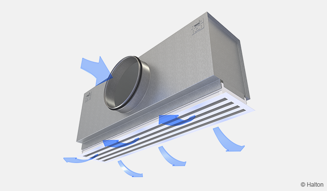
Supply air is supplied through the linear slots of the diffuser horizontally along the ceiling surface or vertically into the occupied zone.
For wall installation, the plane jet air is supplied horizontally or directed to the ceiling surface, which increases the throw length.
For an exhaust application, the diffuser is supplied without flow control vanes.
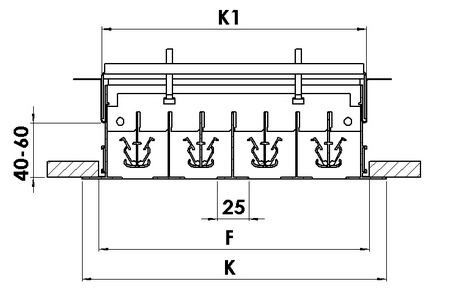
Installation
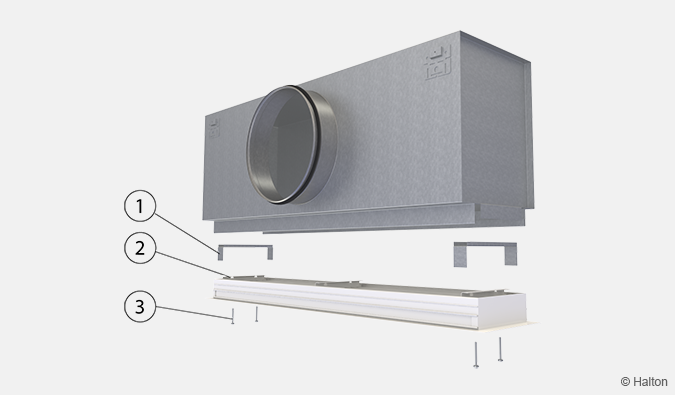
Key
1. Mounting bracket
2. Transversal bar
3. Screw
The Halton SLM linear slot diffuser is connected directly to the Halton PLM or Halton PMM plenum.
The plenum is installed into the suspended ceiling with M8 drop rods (not included in the delivery) and connected to the ductwork.
Remove the T-profiles of the Halton SLM by pulling them gently, in order to access the transversal bars located behind the profiles.
Fit the installation brackets into the grooves of the plenum and secure with the screws supplied with the unit.
Put screws into the holes of the transversal bars. Screw on until the diffuser is flush to the ceiling.
Replace the T-profiles.
The unit can be installed without plenum using the staff brackets. Those pieces are available as accessory (2 by slad or by linear meter).
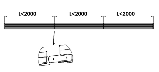
String course mounting
The maximum length is 2000 mm. So when length is superior to 2000 mm, it is necessary to place side by side several pieces. Some alignement guides are given in order to make the the mounting easier.
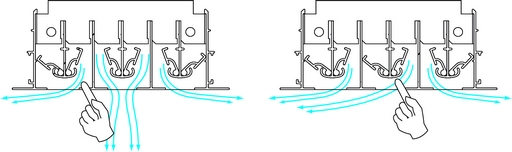
Adjustment
The air pattern can be changed through 180° by adjusting the flow deflection vanes using a screwdriver. Each deflection vane section can be individually adjusted without removing the T-profiles in order to provide flexibility in supply air pattern orientation.
Diffusers are delivered unadjusted with the flow deflection vanes in the open position.
To aid in adjusting and measuring the airflow rate, it is recommended that the diffuser is connected to a plenum equipped with a MSM.
The supply airflow is determined by measuring the pressure difference with a measurement module.
Measure the differential pressure with a manometer. The airflow rate is calculated according to the following formula:
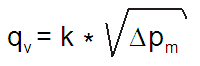
∆Pm Measured pressure [Pa]
k Factor given as a function of mounting and diameter
Qv Airflow rate [l/s]
The k factor for installations with different safety distances
(distance of other items from the MSM):
| Safety distance | ||
| NS | > 6xD | min 3xD |
| 160 | 19 | 22 |
| 200 | 49 | 32 |
| 250 | 51 | 51 |
Adjust the airflow rate by rotating the control spindle until the desired setting is achieved.
Lock the damper in position with a screw.
Replace the tubes and spindle in the plenum, and return the linear diffuser to its position.
Servicing
Remove the T-profiles.
Remove the linear diffuser by unscrewing the screws of the transversal bars.
Clean the parts by wiping them with a damp cloth.
Push the linear diffuser back into place by screwing the transversal bars to the installation brackets.
Option:
With balancing plenum Halton PLM + MSM/MEM or Halton PMM + MSM/MEM
Remove the measurement and adjustment module by gently pulling the shaft; (not the control spindle or measurement tubes!).
Wipe the parts with a damp cloth, instead of immersing in water.
Reassemble the measurement and adjustment module by pushing the shaft back into place until the module meets the stopper.
Push the linear diffuser back into place by screwing the transversal bars to the installation brackets.
Specification
Halton-brand ceiling diffuser, type Halton SLM, with one to four slots, suitable for variable airflow
Excellent coanda effect provided with a wide range of airflow rates.
Each air pattern adjustment section shall comprise two flow deflection vanes.
The supply air pattern is directable by adjusting the flow deflection vanes without any change in the appearance of the diffuser.
The linear slot diffuser has an extruded aluminium outer frame, flow deflection vanes and T- profiles, and or polyester-painted to white (RAL 9003) colour.
The diffuser is connected to the ductwork using a plenum with mineral wool as sound attenuation material.
The removable linear slot diffuser is mounted into the plenum with invisible screws.
The plenum comprises an airflow measurement and adjustment module.
The linear diffuser is removable in order to provide access to the measurement and adjustment module in the plenum.
Flow deflection vanes and T-profiles are easily removable for access to the plenum.
Order code
SLM/S-N-L; FP-SE-ST-FI-CO-ID-ZT
S = Model
S Supply
E Exhaust
O Opening front
N = Number of slots
1, 2, 3, 4
L = Active length (mm)
400, +1, .., 50000
Other options and accessories
FP=Front plate option (available from Crépy factory)
N No
TC TC Ceiling
FC Fineline Ceiling
SE = End caps
Y Yes
N No
ST = Type of end caps
NA Not assigned
N2 Standard (32 mm)
O3 Only one end cap (32 mm)
FI = Finishing
PN Painted
MF Mill finished
CO = Colour
SW Signal white (RAL 9003)
X Special colour (RAL xxxx)
N No painting
ID = Diffuser assembled with plenum (available from Crépy factory)
N No
Y Yes
ZT = Tailored products
N No
Y Yes (ETO)
Sub products
PLM Plenum
PMM Plenum
Code example
SLM/S-1-400, FP=N, SE=Y, ST=N2, FI=PN, CO=SW, ID=N, ZT=N
Downloads
"*" indicates required fields
Halton APL – Jet air diffuser
product
Halton APS – Jet air diffuser
product
Halton BCF – Floor diffuser
product
Halton CAR – Conical diffuser
product
Halton DAC – Square diffuser
product
Halton DCS – Modular diffuser
product
Halton DFA – Square conical diffuser
product
Halton DFB – Conical diffuser
product
Halton DRV – Multi-nozzle terminal unit
product
Halton IAO – Jet nozzle diffuser
product
Halton Jaz JCC – Diffuser
product
Halton Jaz JDA – Diffuser with side slot
product
Halton Jaz JDB – Diffuser with side slot
product
Halton Jaz JDS – Variable air volume diffuser unit (VAV)
product
Halton Jaz JMC – Nozzle diffuser
product
Halton Jaz JRC – Perforated diffuser
product
Halton Jaz JRP – Swirl diffuser
product
Halton Jaz JSC – Nozzle diffuser
product
Halton Jaz JTH – Swirl diffuser
product
Halton Jaz JWC – Swirl diffuser
product