Product / FLU
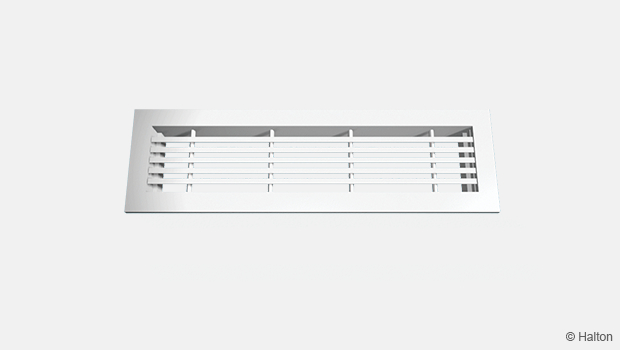
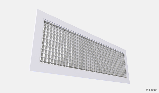
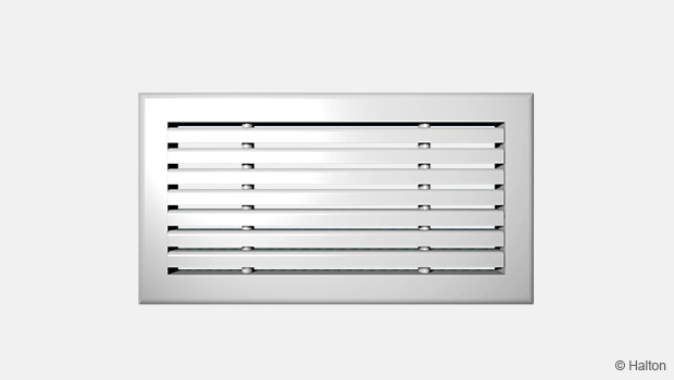
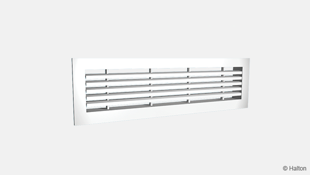
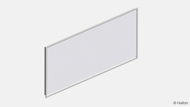
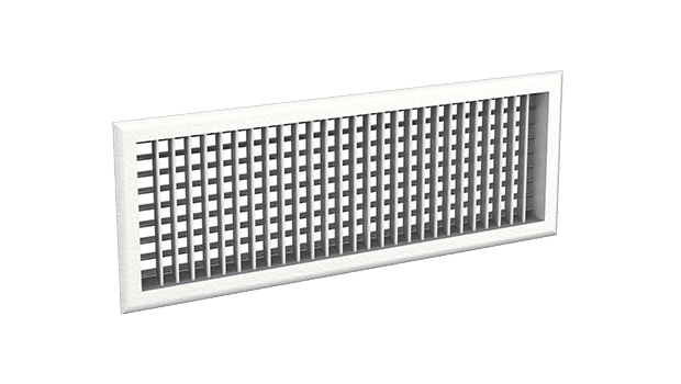
Halton FLU – Floor grille
Terminated as of 01.03.2026
-> replaced with Halton FLE
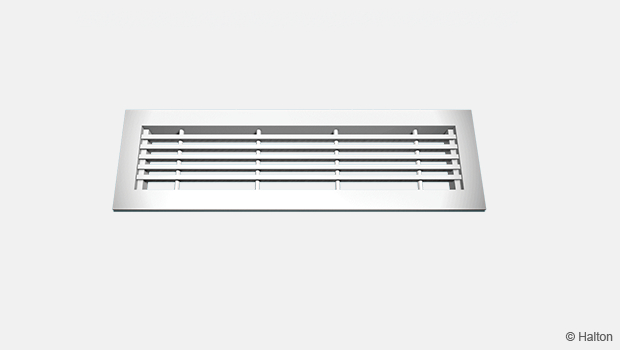
Walkable grille with 0° angle deflection.
- Vertical supply from floor, suitable also for exhaust
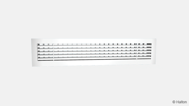
- Fixed front vanes, stable throw pattern, no deflection from the jet centerline
Overview
Terminated as of 01.03.2026
-> replaced with Halton FLE
- Vertical supply from floor, suitable also for exhaust
- Fixed front vanes, stable throw pattern, no deflection from the jet centerline
- Strong aluminium construction, class K3 according the standard NF-EN 1253-2
- Detachable grille allows cleaning of the grille and ductwork
- Continuous grilles available with modular design
Prioduct models and accessories
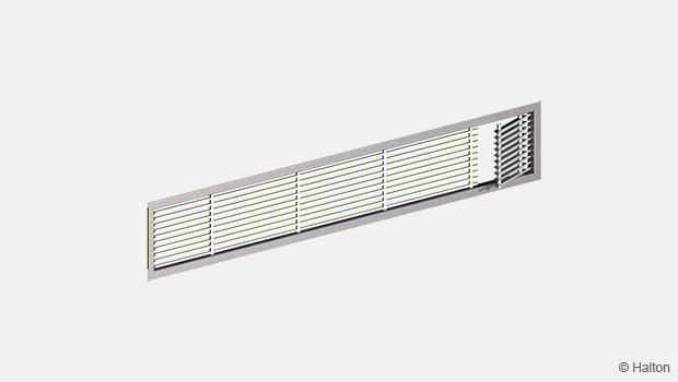
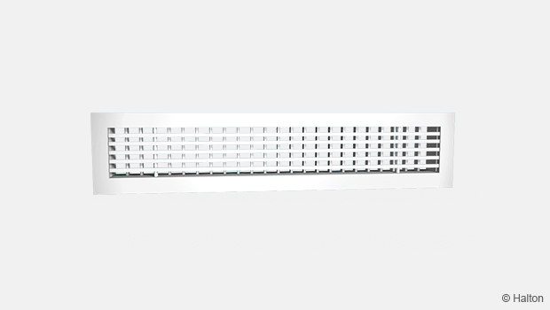
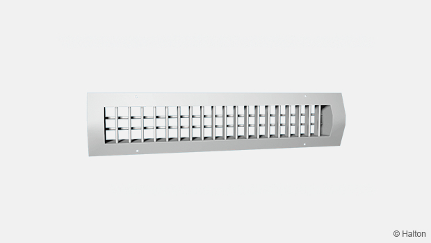
- Model with removable core vanes
- Airflow adjustment damper
- Installation frame
Dimensions
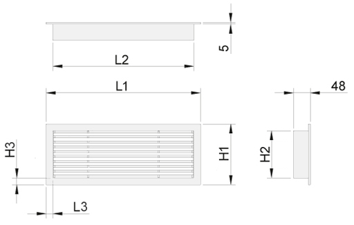
Flat frame, 18 mm (S=A)
| LxH | L1 | L2 | L3 | H1 | H2 | H3 |
| 300×100 | 312 | 276 | 18 | 112 | 76 | 18 |
| 600×100 | 612 | 576 | 18 | 112 | 76 | 18 |
| 1000×100 | 1012 | 976 | 18 | 112 | 76 | 18 |
| 300×150 | 312 | 276 | 18 | 162 | 126 | 18 |
| 400×150 | 412 | 376 | 18 | 162 | 126 | 18 |
| 600×150 | 612 | 576 | 18 | 162 | 126 | 18 |
| 800×150 | 812 | 776 | 18 | 162 | 126 | 18 |
| 1000×150 | 1012 | 976 | 18 | 162 | 126 | 18 |
| 1000×200 | 1012 | 976 | 18 | 212 | 176 | 18 |
Rounded frame, 25 mm (S=B)
| LxH | L1 | L2 | L3 | H1 | H2 | H3 |
| 300×100 | 326 | 276 | 25 | 126 | 76 | 25 |
| 600×100 | 626 | 576 | 25 | 126 | 76 | 25 |
| 1000×100 | 1026 | 976 | 25 | 126 | 76 | 25 |
| 300×150 | 326 | 276 | 25 | 176 | 126 | 25 |
| 400×150 | 426 | 376 | 25 | 176 | 126 | 25 |
| 600×150 | 626 | 576 | 25 | 176 | 126 | 25 |
| 800×150 | 826 | 776 | 25 | 176 | 126 | 25 |
| 1000×150 | 1026 | 976 | 25 | 176 | 126 | 25 |
| 1000×200 | 1026 | 976 | 25 | 226 | 176 | 25 |
With flow control damper OD total depth = 48 mm + 45 mm.
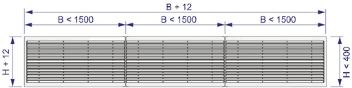
Special dimensions
In addition to standard sizes, other sizes can be specially ordered. The maximum size is 1500×300 mm (LxH).
It is possible to have a continuous grille of modular design when the installation length is greater than 1500 mm. The maximum total length is 20 m.
Material
| Part | Material | Finishing |
| Frame | Aluminium | Anodised or mill finished |
| Vanes | Aluminium | Anodised or mill finished |
| Installation frame | Galvanised steel | – |
The bevel angles of the outer frame have been welded so that the joints are almost invisible.
Accessories
| Product model | Code | Description |
| Model with removable core vanes |
AV | Vanes can be removed to allow access to plenum |
| Accessory | Code | Description |
| Flow adjustment damper | OD | Aluminium opposite blade damper for airflow adjustment |
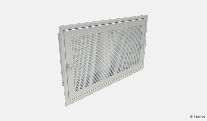
| Installation frame | IF | For the installation of the grille |
| Concealed screw fastening | CC | For installation with IF frame |
| Visible screw fastening | SF | Screw fastening with 25 mm wide frame |
| Flat installation frame | A | 18 mm wide – 48 mm high frame |
| Rounded installation frame | B | 25 mm wide – 48 mm high frame |
Function
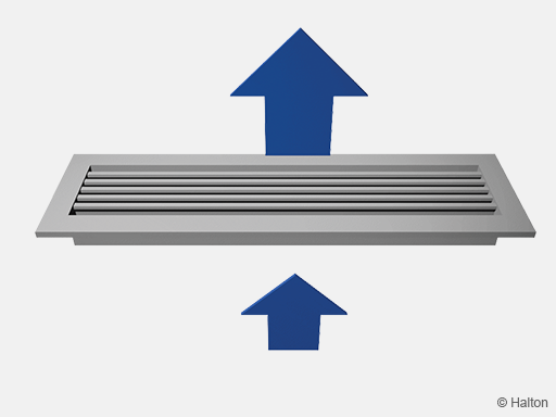
Supply air is supplied without deflection through the horizontal vanes into the space. Supply air mixes with room air in front of the grille.
The Halton FLU grille can also be used as an exhaust unit.
The Halton FLU grille has a high load resistance, with a class K3 according the standard NF-EN 1253-2, (test report CSTB n°CAPE AT 16-009).
The class K3 is defined in the standard as: “Area without at the vehicle traffic, like common place, shopping centers, and some public buildings”
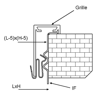
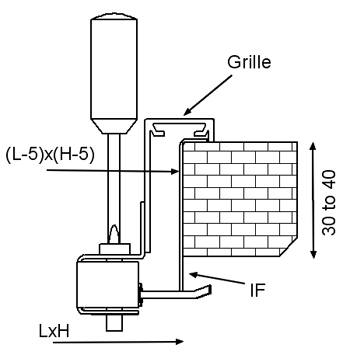
Installation

The grille is connected to the floor plenum using the IF installation frame. (1).
Clips fastening (standard)
The grilles are supplied with clips fastening as standard with the IF installation frame.
Concealed screw fastening (option)
Concealed screw fastening is possible when the grille is installed with an installation frame (IF).
Visible screw fastening (option)
Visible screw fastening is possible with the 25 mm wide frame.
The auto screws, 4.2×25 (bevel headed screw) are supplied.
The size of the installation hole is LxH when an installation frame is used, and (L-5)x(H-5) without an installation frame.
Adjustment
Airflow adjustment damper OD
The airflow rate is adjusted by turning the damper blades behind the grille with a screwdriver. The measurement is carried out when the grille is installed.
Servicing
The grille can be removed for cleaning.
Remove from the floor, by gently pulling the grille from the outer frame. Use a screwdriver, if necessary.
Clean the components with a damp cloth. They must not be immersed in water.
Push the grille back into place, so that the springs lock.
Specification
The floor grille has horisontal fixed vanes without deflection, and an 18 mm wide flat or 25 mm rounded frame, with an anodised standard finishing.
The floor grille can be used for both supply or exhaust air.
The bevel angles of the outer frame is welded so that the joints are almost invisible.
The floor grille is mechanically strong in order to bear external loads.
The floor grill is detachable in order to provide access to the duct.
Order code
FLU/S-L-H; FS-FI-ZT
S = Frame option
A Frame 18 x 45
B Frame 25 x 45
L = Length (mm)
200, +1, .., 20000
H = Height (mm)
100, +1, .., 300
Other options and accessories
FS = Fastening
CL Clips
CC Concealed screw fastening
SF Screw fastening
FI = Finishing
AN Anodised
MF Mill finished
ZT = Tailored product
N No
Y Yes (ETO)
Sub products
BDR Plenum
PRL Plenum
IF Installation frame (Grilles)
OD Opposed blade damper (Grilles)
Code example
FLU/A-200-100, FS=CL, FI=AN, ZT=N
Downloads
"*" indicates required fields
Halton AGC – Exhaust grille
product
Halton AHD – Exhaust grille
product
Halton ALE – Universal grille
product

Halton ALU – Universal grille
product
Halton ASC – Window bench grille
product
Halton AWE – Universal grille
product
Halton AWU – Universal grille
product
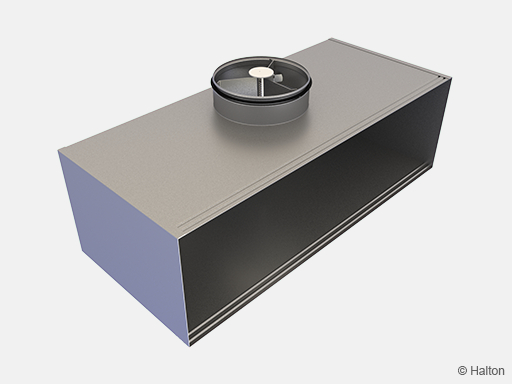
Halton BDR – Plenum for grilles
product

Halton BOS – Supply air valve
product
Halton EVA – Exhaust air unit
product
Halton FLE – Floor grille
product
Halton FLU – Floor grille
product
Halton GDD – Grille for circular duct installation
product

Halton GSP – Floor grille
product
Halton HDF – Exhaust grille with filter
product
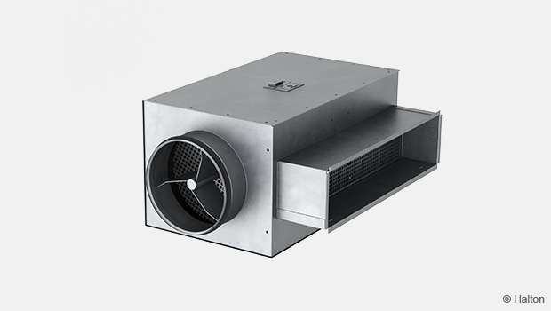
Halton PRL – Plenum for grilles
product
Halton Vita VSC – Exhaust unit
product
Halton Vita VSG – Exhaust grille
product
Halton WDD – Universal grille
product