Product / HDF
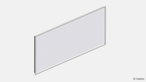
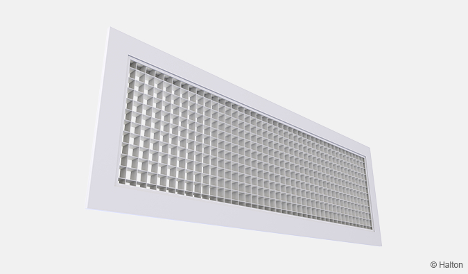
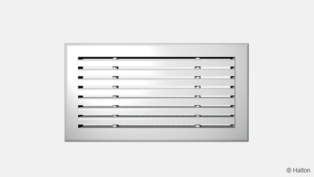
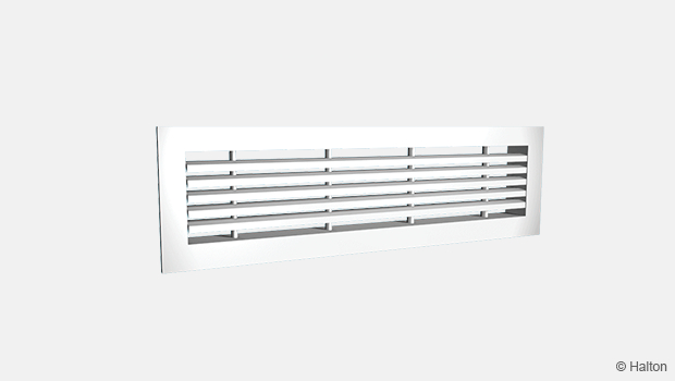
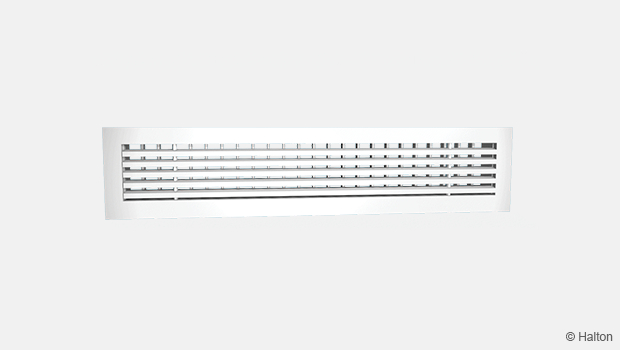
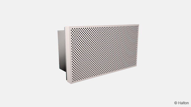
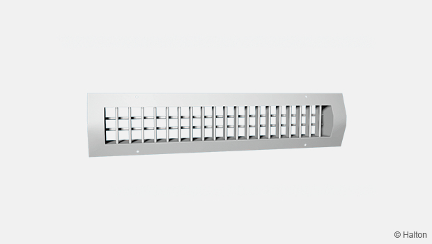
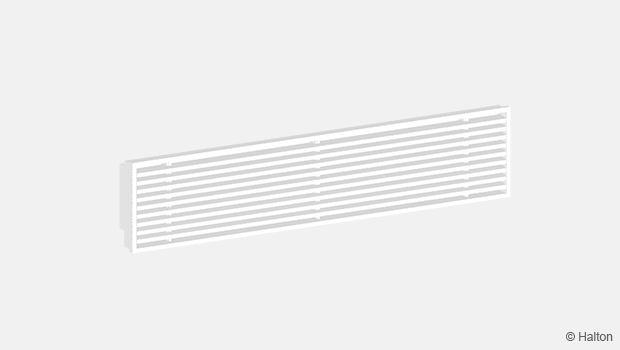
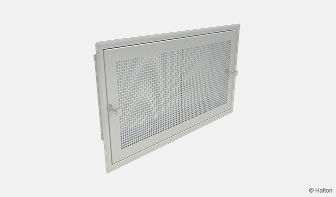
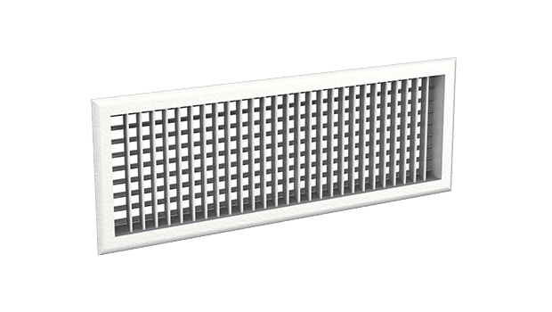
Halton HDF – Exhaust grille with filter
Aesthetic in design.
Exhaust grille with filter, reduced visibility through grille.
- Large free area
- Integrated filter of class EU3
Overview
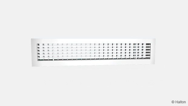
- Large free area
- Integrated filter of class EU3
- Reduced visibility through grille due to shaped horizontal vanes
- Sizes adapted to suit modular 600 x 600 mm suspended ceilings
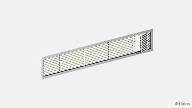
- Openable core vanes for direct access to the filter
- Screw fastening
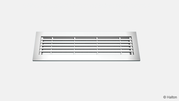
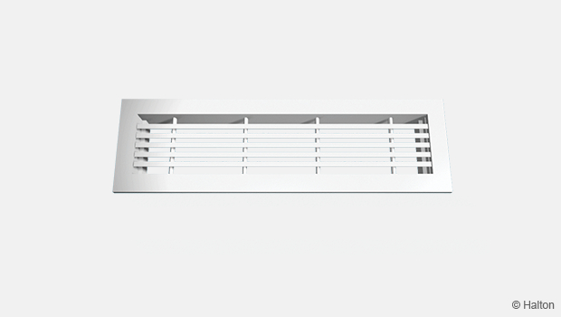
Product models and accessories
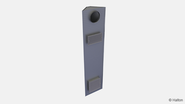
- Airflow adjustment damper
- Balancing plenum with measurement and adjustment functions
- Plenum insulation
- Spare filter
Dimensions
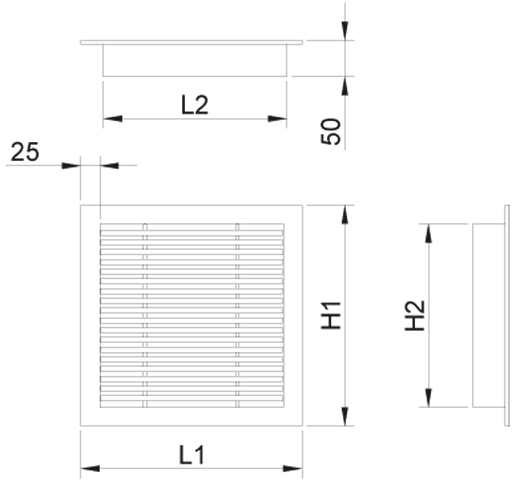
| LxH | L1 | L2 | H1 | H2 |
| 570×270 | 595 | 545 | 295 | 245 |
| 570×570 | 595 | 545 | 595 | 545 |
With flow control damper OD total depth = 50 mm + 45 mm.
The free area of the HDF grille is 75%.
Material
| Part | Material | Finishing | Note |
| Frame | Aluminium | Mill-finished, anodised, or polyester-painted as white (RAL 9003/30% gloss) |
Epoxy-painting (100%) available |
| Fixed vanes | Aluminium | Mill-finished, anodised, or polyester-painted as white (RAL 9003 / 30% gloss) |
Epoxy-painting (100%) available |
| Air filter | Frame in galvanised steel Filter in polyester |
– | EU3 class (Eurovent 4/5 method) |
| Plenum box, spigot |
Galvanised steel | – | – |
Accessories
| Accessory | Code | Description |
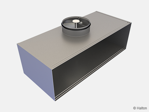
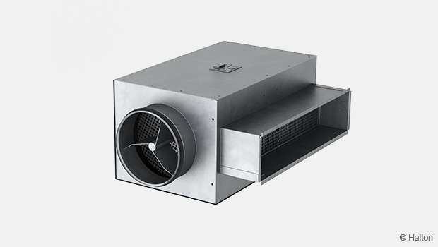
| Special plenum for HDF | Special BDR | Plenum for duct connection (with or without attenuation material), please contact Customer Service |
| Airflow measurement and adjustment unit |
MEM | For exhaust installation |
| Sound attenuation | IN | Mineral wool for the special BDR plenum box |
| Filter | FI | Spare filter |
Function
Air is exhausted from the space with a low pressure drop.
Wall or ceiling installation.
Installation
The grille is connected to the duct using a special BDR plenum.
The grille is fastened in place with invisible screws (not supplied), which are screwed in through the frame.
Dimensions of opening
| LxH | Opening |
| 570×270 | 565×265 |
| 570×570 | 565×565 |
Adjustment
In order to enable adjustment and measurement of the airflow rate, it is recommended that you connect the diffuser to the special BDR plenum equipped with the MEM module.
The airflow rate can be adjusted and measured only when the grille is connected to the special BDR plenum.
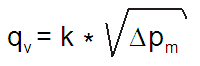
Define the exhaust airflow rate by measuring the pressure difference between the measurement tap on the special BDR plenum and the room air. The corresponding airflow rate is calculated using the formula below.
Adjust the airflow rate by turning the control spindle of the MEM.
K factor for installations with different safety distances
(D= duct diameter)
| BDR (Special) |
> 6xD | min. 3xD |
| 100 | 6 | 7 |
| 125 | 10 | 12 |
| 160 | 19 | 22 |
| 200 | 28 | 32 |
| 250 | 49 | 51 |
| 315 | 77 | 83 |
Airflow adjustment damper OD
The airflow rate is adjusted by turning the damper blades behind the grille with a screwdriver. The measurement is performed when the grille is installed.
Servicing
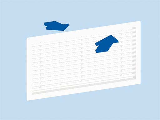
Remove the grille by gently drawing it out by the frame. Use a screwdriver if necessary.
Clean the parts by wiping with a damp cloth.
The filter can be removed for replacement by sliding sideways.
Push the grille back into place until the springs lock.
Option: With balancing plenum Halton PRL+MEM or Halton BDR+MEM
Remove the measurement and adjustment module by gently pulling the shaft (not the control spindle).
Wipe the parts with a damp cloth, instead of immersing in water.
Reassemble the measurement and adjustment module by pushing the shaft back into place until the module meets the stopper.
Push the grille back into place so that the springs lock.
Specification
The exhaust grille shall have a large free area.
Non-clogging lightweight construction with fixed curved vanes shall prevent visibility through the grille. The joints of the outer frame shall be practically invisible.
The grille shall be mill-finished, anodised, or polyester-painted with a white (RAL 9003) standard colour.
Sizes 570 x 270 mm and 570 x 570 mm shall be adapted to modular 600 x 600 mm suspended ceilings.
The grille shall comprise a filter of EU3 class (Eurovent method 4/5).
The grille shall be connected to the duct using a plenum.
The Halton BDR or PRL plenum shall utilise sound attenuation material made of mineral wool (optional).
Airflow measurement and adjustment unit MEM is available as an accessory to plenum.
The exhaust grille shall be openable in order to provide direct access to the filter.
Order code
HDF/L-H; FI-CO-ZT
L = Length (mm)
570
H = Height (mm)
270, 570
Other options and accessories
FI = Finishing
AN Anodised (class 10 um)
MF Mill finished
PN Painted
CO = Colour
SW Signal white (RAL 9003)
X Special colour (RAL xxxx)
N No painting
ZT = Tailored product
Y Yes
N No (ETO)
Sub products
BDR Plenum
PRL Plenum
FI Filter
Code example
HDF-570-270, FI=AN, CO=N, ZT=N
Downloads
"*" indicates required fields
Halton AGC – Exhaust grille
product
Halton AHD – Exhaust grille
product
Halton ALE – Universal grille
product

Halton ALU – Universal grille
product
Halton ASC – Window bench grille
product
Halton AWE – Universal grille
product
Halton AWU – Universal grille
product
Halton BDR – Plenum for grilles
product
Halton BOS – Supply air valve
product
Halton EVA – Exhaust air unit
product
Halton FLE – Floor grille
product
Halton FLU – Floor grille
product
Halton GDD – Grille for circular duct installation
product
Halton GSP – Floor grille
product
Halton HDF – Exhaust grille with filter
product
Halton PRL – Plenum for grilles
product
Halton Vita VSC – Exhaust unit
product
Halton Vita VSG – Exhaust grille
product
Halton WDD – Universal grille
product