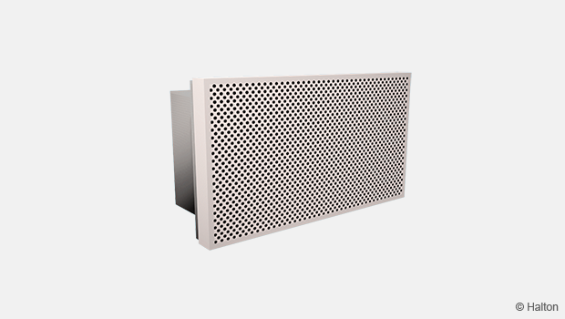
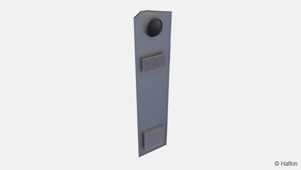
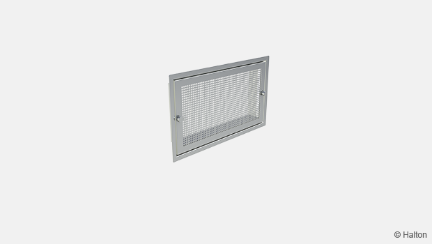
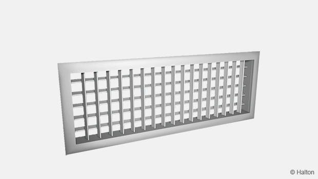
Product / EVA
Overview
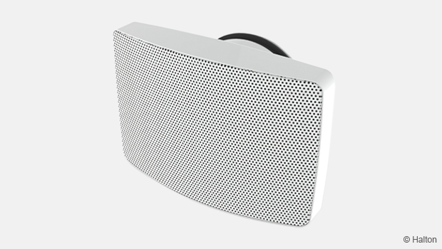
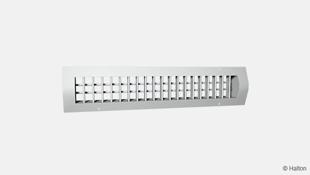
- Exhaust air unit with airflow measurement and adjustment arrangement
- Wide pressure drop range with low noise level
- Installation with balancing plenum or directly to rectangular ductwork
- Detachable front panel enables cleaning of the unit and ductwork
Accessories
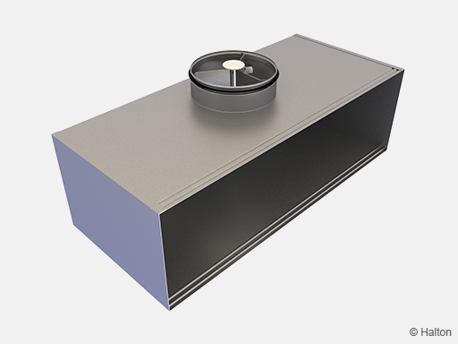
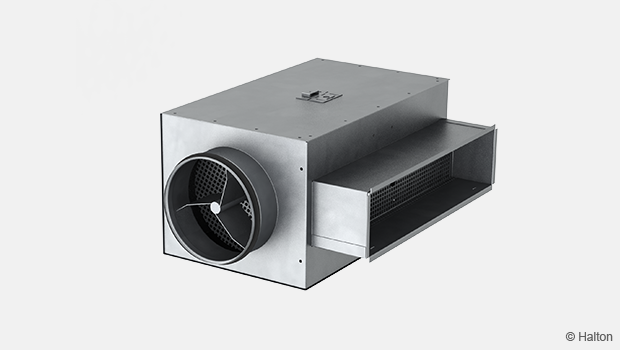
- Balancing plenum with circular duct connection
Quick selection

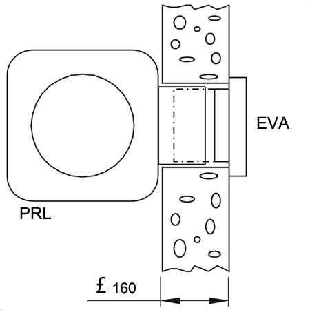
Fig.1. Without plenum

Fig.2. With Halton PRL plenum
Dimensions
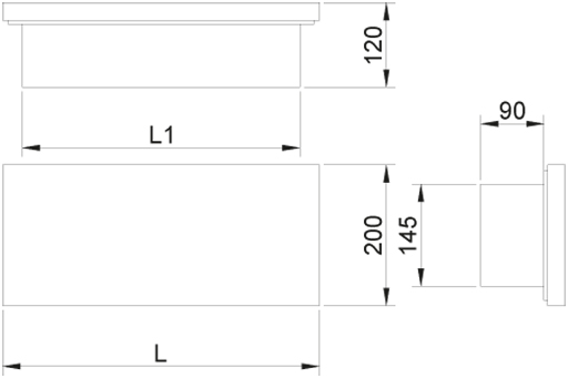
| NS | L | L1 |
| 300×150 | 350 | 295 |
| 500×150 | 550 | 495 |
| 800×150 | 850 | 795 |
Weight
| NS | kg |
| 300×150 | 2.5 |
| 500×150 | 3.6 |
| 800×150 | 5.4 |
Material
| Part | Material | Note |
| Front panel | Perforated steel | – |
| Adjustment module |
Aluminium | Black as standard colour |
| Casing | Galvanised steel | – |
| Finishing | Painted / White (RAL 9003/30%) |
Special colours available |
Function
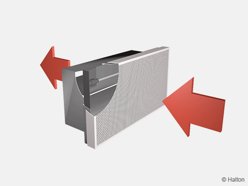
Air in Halton EVA is exhausted through the front panel. The valve throttles the exhaust airflow and attenuates duct noise. The pressure drop and airflow rate are dependant on the distance of the cone elements of the adjustment module. The desired exhaust airflow rate is adjusted during the balancing of the airflows in a ductwork system.
Installation
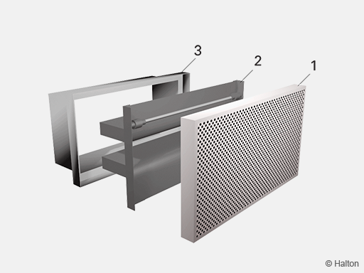
Code description
1. Front panel
2. Adjusment module
3. Casing
The Halton EVA exhaust unit is connected either directly to the duct by screwing or by riveting or alternatively to the Halton PRL balancing plenum
(models without flow control damper, but with sound attenuation material).
When the Halton EVA unit is installed to a Halton PRL balancing plenum, the Halton EVA casing (3) replaces the telescopic collar of the Halton PRL thus making the Halton PRL collar unnecessary.
Dimension of wall or ceiling openings
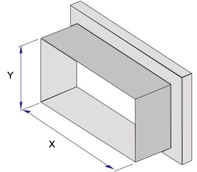
| NS | X | Y |
| 300×150 | 298 | 148 |
| 500×150 | 498 | 148 |
| 800×150 | 798 | 148 |
Adjustment
Measure the differential pressure using a manometer. The flow rate is calculated using the formula below:

Adjust the airflow rate by turning the adjustment spindle until the desired setting is achieved.
Note!
Airflow rate adjustment is carried out using the adjustment arrangement of the Halton EVA exhaust unit even when connected to Halton PRI balancing plenum.
The k factor for different adjustment module openings (A)
| Size | 300×150 | 500×150 | 800×150 |
| A | k | k | k |
| 0 | 1.90 | 3.54 | 6.00 |
| 1 | 2.68 | 5.66 | 10.95 |
| 2 | 4.02 | 8.49 | 14.61 |
| 3 | 5.77 | 11.18 | 18.26 |
| 4 | 7.07 | 14.14 | 23.57 |
| 5 | 9.00 | 16.43 | 28.00 |
| 6 | 10.61 | 18.97 | 32.27 |
| 7 | 12.50 | 21.00 | 35.00 |
Servicing
Detach the perforated front panel of Halton EVA by gently pulling.
Remove the adjustment module by opening the clips.
Wipe the parts with a damp cloth. Do not immerse in water.
Reassemble the adjustment module so that the clips lock.
Push the front panel into place so that the clips lock.
Specification
The exhaust unit has a telescopic casing made of galvanised steel.
The unit comprises internal removable adjustment module and detachable perforated front panel.
The front panel is attached to the casing with clips.
The unit has a fixed measurement tap for airflow measurement.
The airflow is adjustable by rotating the adjustment spindle.
Order code
EVA-W-H, CO-ZT
W = Width [mm]
300, 500, 800
H = Height [mm]
150
Other options and accessories
CO = Colour
SW Signal white (RAL 9003)
X Special colour (RAL xxxx)
ZT = Tailored product
N No
Y Yes (ETO)
Sub products
PRL Balancing plenum
Code example
EVA-300-150, CO=SW, ZT=N
Downloads
"*" indicates required fields
