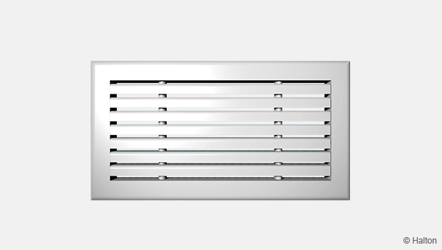
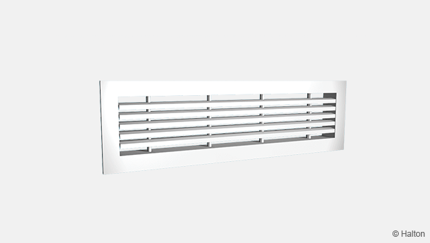
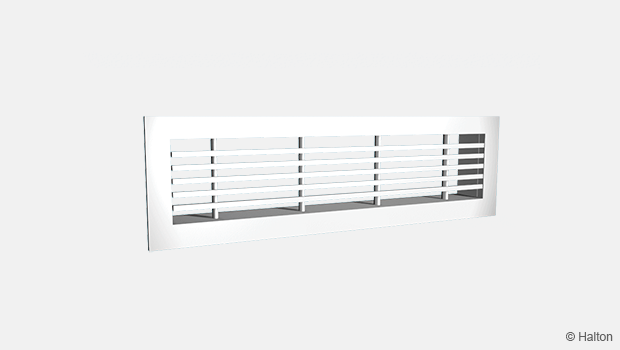
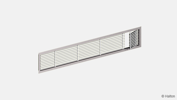
Product / BDR
Overview
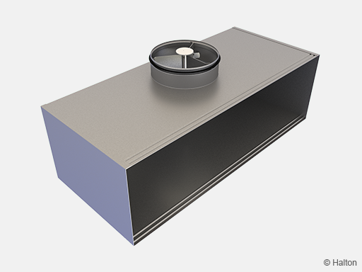
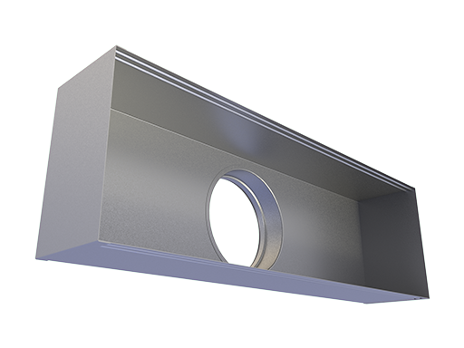
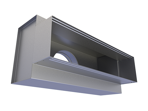
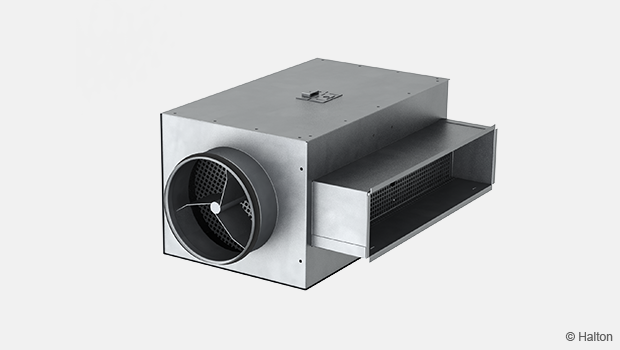
- Plenum for connecting supply/exhaust grille to ductwork
- Ensures proper function of the supply air diffuser
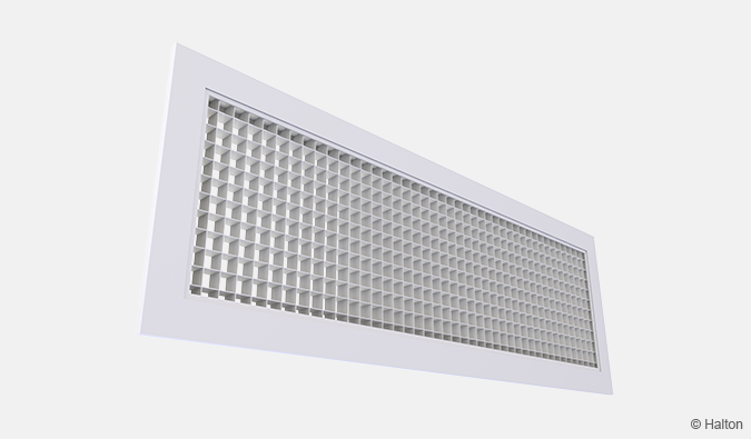
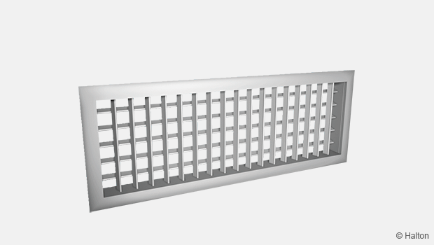
- Wide range of grille dimensions and models
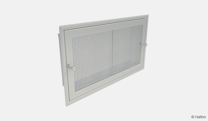
- Spring clips fastening of the grille
- Access for ductwork cleaning
Product models and accessories
- Model with sound attenuation material
- Detachable airflow rate measurement and adjustment module
Dimensions
| Selectable dimension | Determined dimension | Note |
| L (Nominal length) |
Inner dimension always L-5 mm | Nominal length is selected according to the length of the attachable grille |
| H (Nominal height) |
Inner dimension always H-5 mm | Nominal height is selected according to the length of the attachable grille |
| D (Size of duct connection) |
W1 = D/2+30 mm | For BDR/S-T and BDR/S-S |
| W1 = W/2 | For other configurations with W1 dimension |
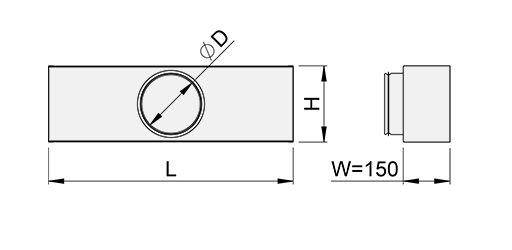
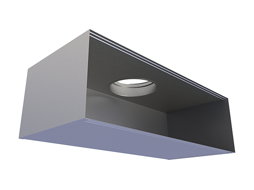
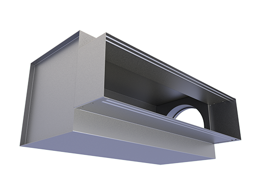
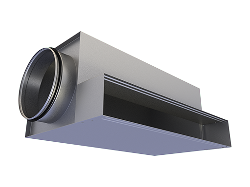
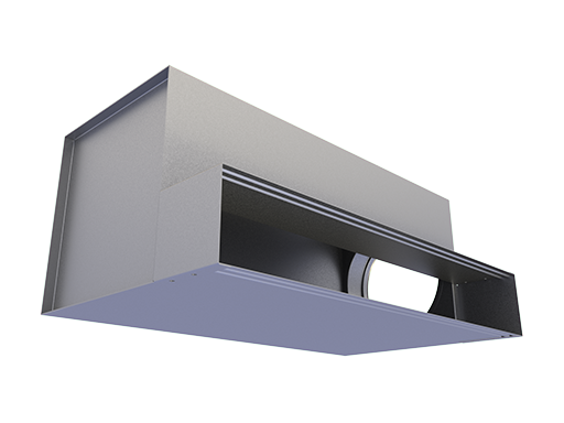
Fig.1. Standard model with back connection (BDR/S-B)
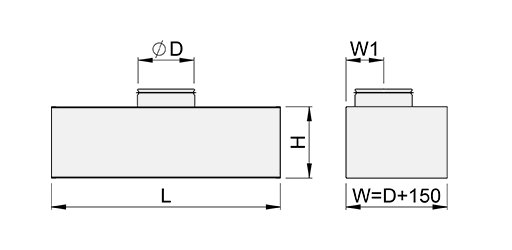
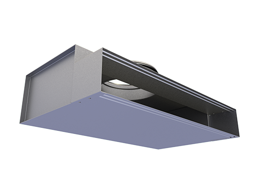
Fig.2. Standard with top connection (BDR/S-T)
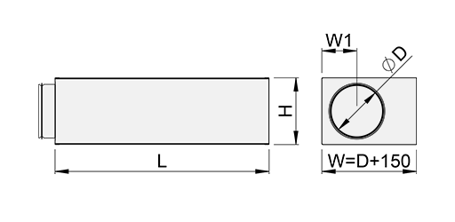
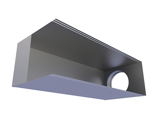
Fig.3. Standard with side connection (BDR/S-S)
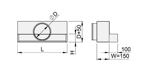
Fig.4. L-shape with back connection (BDR/L-B)
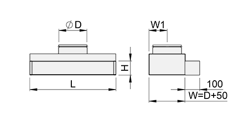
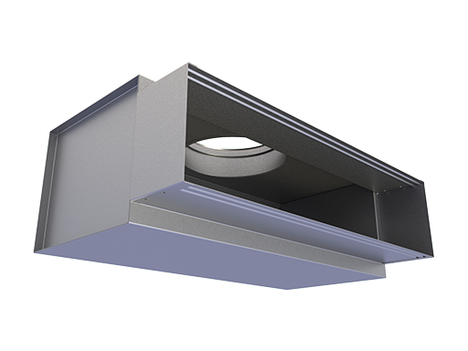
Fig.5. L-shape with top connection (BDR/L-T)
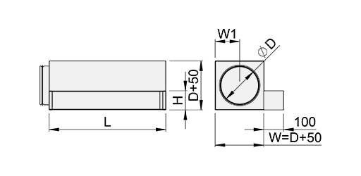
Fig.6. L-shape with left connection (BDR/L-L)
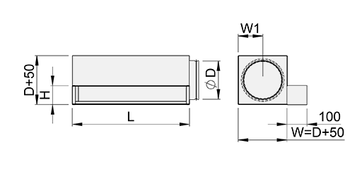
Fig.7. L-shape with right connection (BDR/L-R)
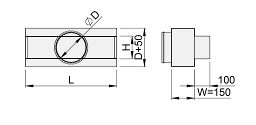
Fig.8. T-shape with back connection (BDR/T-B)
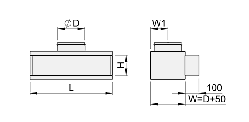
Fig.9. T-shape with top connection (BDR/T-T)
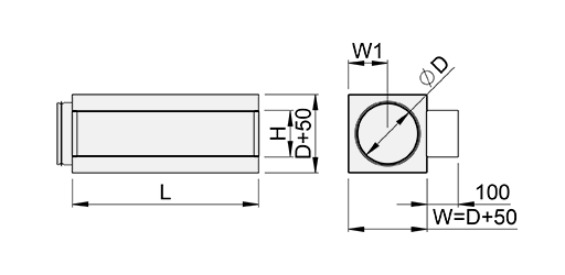
Fig.10. T-shape with side connection (BDR/T-S)
Material
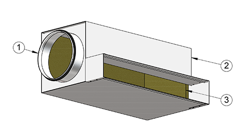
| No. | Part | Material | Note |
| 1 | Spigot | Galvanised steel | – |
| 2 | Plenum box | Galvanised steel | – |
| 3 | Insulation | Mineral wool or polyester fibre | The mineral wool is fixed with nails |
Accessories
| Accessory | Code | Description |
| Sound attenuation | IN | Mineral wool on 2 sides in the BDR plenum |
| Sound attenuation | IN | Mineral wool on 5 sides in the BDR plenum |
| Airflow measurement and adjustment unit |
MSM | For supply installation (for spigot with diameter Ø 315) |
| Airflow measurement and adjustment unit |
MEM | For exhaust installation |
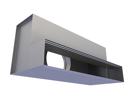
Product models
|
Location of duct connection |
Model | ||
| S (Standard) |
L (L-shape) |
T (T-shape) |
|
| B (Back) |
*
|
 |
*
|
| T (Top) |
 |
 |
 |
| S (Side) |
 |
– |  |
| L (Left) |
– |  |
– |
| R (Right) |
– |  |
– |
* Available only when height is over 150 mm.
Function
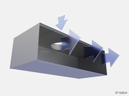
The duct pressure and air velocity are reduced inside the Halton BDR plenum box. Consequently supply air is evenly spread over the surface of the grille. The airflow rate can be adjusted using the optional measurement and adjustment module MSM.
Installation
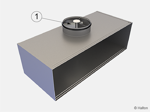
The Halton BDR plenum is connected to the distribution ductwork with a spigot.
When equipped with a measurement and adjustment module (1), the recommended safety distance upstream of the device is at least 3xD, in order to ensure a reliable airflow rate measurement.
The unit’s control spindle must not be excessively bent.
With wall installations the required hole size is at least (L x H).
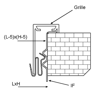
The spigot comprises two grooves to enable the grille springs to lock.
Clip fastening of grille (standard)
Adjustment
In order to enable airflow adjustment and measurement of airflow rate, it is recommended that the grille be connected to the plenum equipped with the MSM module.
The supply flow rate is determined by using the measurement and adjustment module MSM.
Detach the grille and pass the tubes and control spindle through the grille.
Push the grille back into place.
Measure the differential pressure with a manometer. The flow rate is calculated using the formula below.

Adjust the airflow rate by rotating the control spindle until the desired setting is achieved.
Lock the damper position with a screw.
Replace the tubes and spindle into the plenum and replace the grille.
The k-factor for installations with different safety distances
(D=duct diameter)
Supply air
| D | >8xD | min 3xD |
| 125 | 9.9 | 12.6 |
| 160 | 16.9 | 21.9 |
| 200 | 28.3 | 31.0 |
| 250 | 47.9 | 51.5 |
| 315 | 78.6 | – |
Exhaust
The airflow rate is determined by measuring the differential pressure between the measurement tap on the Halton BDR plenum and the room air.
The corresponding airflow rate is calculated using the formula above.
The desired airflow rate can be adjusted by turning the control spindle of the adjustment unit MEM.
Servicing
Remove the measurement and adjustment module by gently pulling the shaft (not the control spindle).
Wipe the parts with a damp cloth, instead of immersing in water.
Reassemble the measurement and adjustment module by pushing the shaft back into place until the module meets the stopper.
Specification
The plenum is made of galvanised steel.
The plenum will comprise an airflow measurement and adjustment unit.
The grille is detachable to provide access to the measurement and adjustment module in the plenum.
The plenum has mineral wool as sound insulation material.
The plenum will reduce duct pressure and air velocity in order to supply air through the whole face area of the grille and improve the air distribution quality.
Order code
BDR/M-L-H-A; D-N-GM-FS-AO-AM-MM-ZT
M = Model
S Standard
L L-shape
T T-shape
L = Length (mm)
200, 201, 202, 203, … +1, .., 20000
H = Height (mm)
50, 51, 52, 53, … +1, .., 670
A = Location of duct connection
B Back
T Top
S Side
L Left
R Right
Other options and accessories
D = Size of duct connection (mm)
100, 125, 160, 200, 250, 315, 355, 400, 450, 500
N = Number of duct connections
1, 2, 3, 4 …, 10
GM = Model of grille
AGC AGC
AHD AHD
ALE ALE
AWE AWU
FLE FLE
FLU FLU
HDF HDF
WDD WDD
FS = Fastening of grille
CL Clips
SF Screw fastening
CC Concealed screw fastening
NA Not assigned
AO = Sound attenuation options
2 Sound attenuation on 2 sides
5 Sound attenuation on sides
NA Not assigned
AM = Sound attenuation material
P Polyester fibre
M Mineral wool
NA Not assigned
MM = Measurement and adjustment module
S MSM in each spigot (supply)
E MEM in each spigot (exhaust)
NA Not assigned
ZT = Tailored product
N No
Y Yes (ETO)
Code example
BDR/L-1000-200-T, D=100, N=1, GM=AGC, FS=CL, AO=NA, AM=NA, MM=NA, ZT=N
Downloads
"*" indicates required fields
