Product / VHR
Halton Vita VHR – HEPA diffuser with blue light disinfection
NEW!
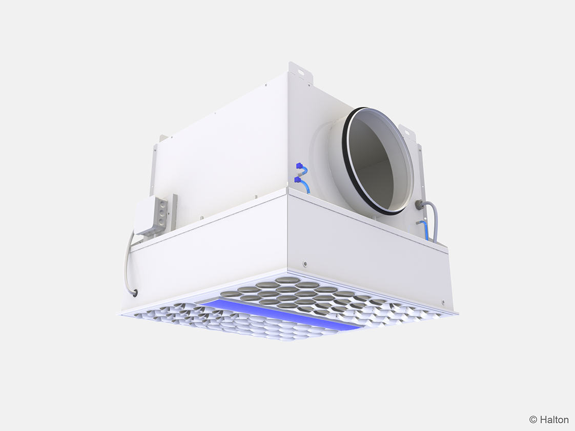
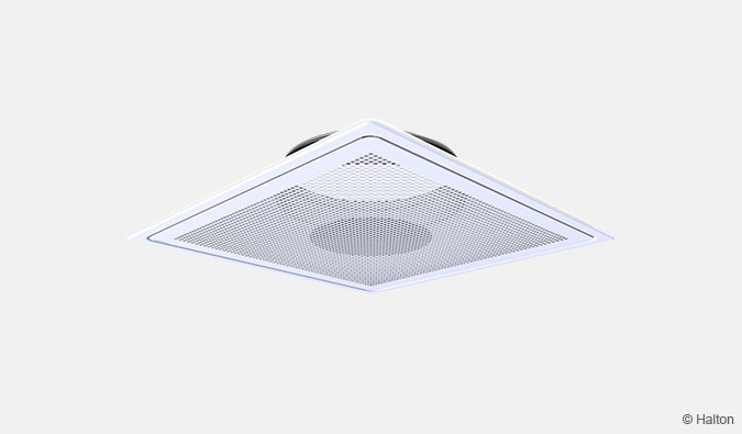
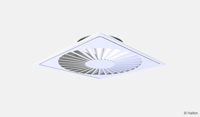
Halton Vita VHR is a HEPA diffuser with integrated disinfection units for spaces where high cleanliness levels are required.
Integrated blue light technology provides a chemical-free disinfection method for surfaces to ensure a safer working environment.
Disinfection units also include white light LEDs for general lighting.
- Spaces with high cleanliness requirements
- Suitable for supply and exhaust ventilation.
- Used with standard and high airflow HEPA filters (classes E10, H13 and H14).
Overview
Halton Vita VHR is a HEPA diffuser with integrated disinfection units for spaces where high cleanliness levels are required. Integrated blue light technology provides a chemical-free disinfection method for surfaces to ensure a safer working environment. Disinfection units also include white light LEDs for general lighting.
Applications
- Spaces with high cleanliness requirements, for example:
- Cleanrooms in hospitals and laboratories
- Industrial cleanrooms
Key features
- Suitable for supply and exhaust ventilation.
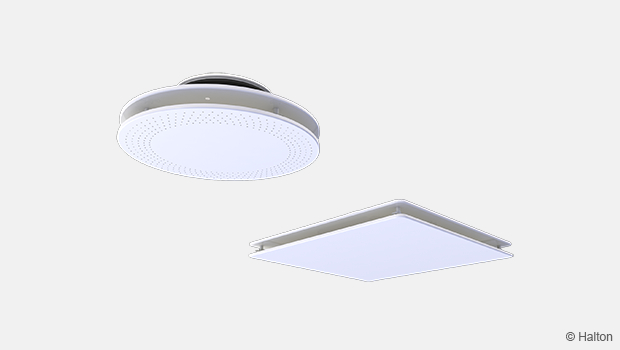
- Air supply through adjustable nozzles or a perforated front panel.
- Installed flush to the ceiling or a wall.
- Blue light disinfection system for improved room hygiene.
- Optimised surface irradiation and disinfection performance due to integrated blue light LEDs.
- High-quality white light LEDs for general room lighting.
- Integrated units allow more space in the false ceiling for other installations.
- Faster installation time due to pre-manufactured units.
- Depending on the used lighting control system, there are two alternative product models available (DALI and On/Off). The product model selection has to be done at latest when ordering the product.
- Antibacterial epoxy-polyester powder paint finishing to prevent microbial growth.
- Used with standard and high airflow HEPA filters (classes E10, H13 and H14).
- Test probes for measuring the filter pressure loss and the particle concentration before the filter. Differential pressure transmitter (optional).
Operating principle
Airflow
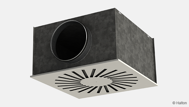
The Halton Vita VHR diffuser can be used both for supply and exhaust air.
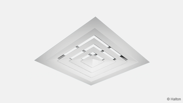
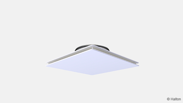
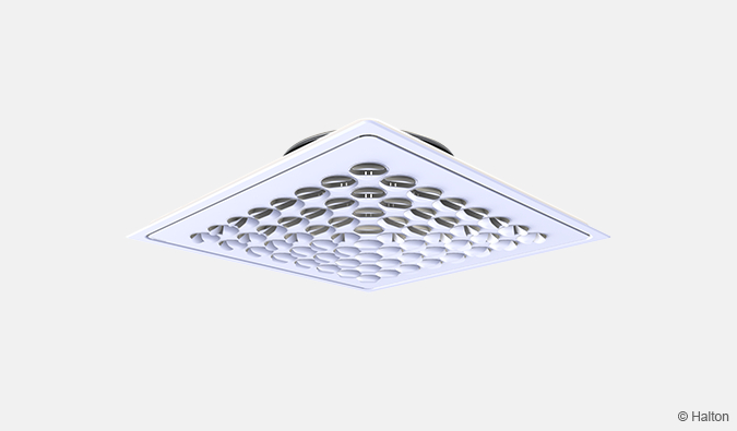
In the supply application, the diffuser supplies the filtered air into the space through adjustable nozzles. The nozzles can be adjusted in 15-degree intervals, which makes it possible to create the desired airflow pattern.
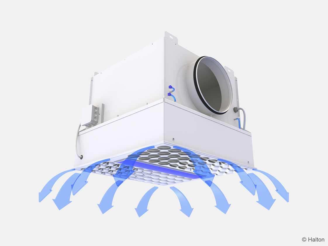
Fig.2. Halton Vita VHR: Supply air
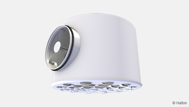
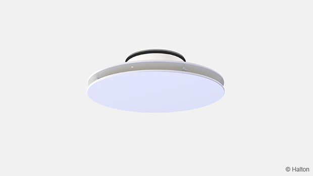
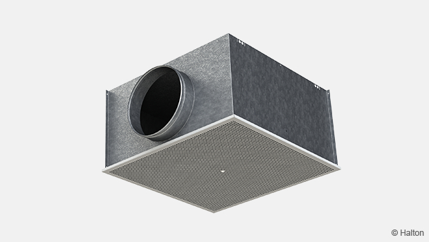
In the exhaust application, the air is exhausted through the perforated front panel and filtered before it flows to the ductwork.
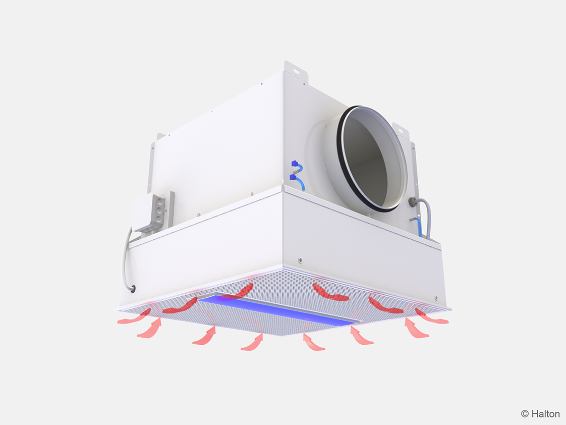
Fig.3. Halton Vita VHR: Exhaust air
Blue light disinfection system
Disinfection units can be integrated into the product. Each unit has both blue light and white light LED elements. The blue light LEDS are used for surface disinfection and the white light LEDs for general lighting.
The ability of blue light to destroy microbes is based on its ability to energise naturally light-sensitive compounds found in all bacteria, yeast, and mold cells. When these compounds are exposed to high-intensity blue light, a natural chemical reaction starts where free oxygen radicals are formed inside cells. These free radicals are highly reactive molecules that start destroying the cells from within by damaging their internal structures. When continued long enough, the reaction destroys the microbes.
The integrated design of disinfection units provides optimised disinfection over the whole operating room with a special emphasis to the critical operating area. Together with the normal, daily cleaning of operating rooms, blue light disinfection makes it easier to keep the operating room surfaces clean and safe.
Benefits:
- Safer operating environment
- Blue light destroys microbes on surfaces.
- Reduced number of microbes in the space.
- Blue light does not develop antimicrobial resistance.
- Disinfection light integrated into the product
- More space in the false ceiling for other installations.
- Faster installation time due to pre-manufactured units.
- Fully automatic system
- The blue light disinfection system can be configured so that it is automatically switched on when the room is not occupied.
- Ensures disinfection and saves time for the staff.
Laboratory tests on the effectiveness of the blue light disinfection system have been carried out in an accredited laboratory. The results show that the blue light photon disinfection produces relevant bacteria reductions. When combined with photocatalytic coating, relevant reductions are achieved already before 30 minutes.
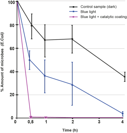
Fig. 4. Bacteria reductions with the blue light disinfection system (LED Taylor Oy)
High quality general room lighting
Blue light disinfection units also include integrated white light LED elements, which enables high-quality general room lighting. This also leads to additional savings in lighting installation and leaves ceiling space free for other installations.
Key technical data
Feature |
Description |
| Airflow rate | Up to 400 l/s. For performace data, see Halton HIT Design tool. |
| Dimensions | 600×600 mm and 1200×600 mm |
| Weight | 18.3 – 45.7 kg (with disinfection units and filters) |
| Size of duct connections | Circular:
Rectangular:
|
| HEPA filter class | E10, H13, H14 |
| HEPA filter depth | 68, 90 mm |
| Blue light LEDs | Power consumption: 90 W per disinfection unit. 1-2 disinfection units depending on the size of the diffuser. |
| White light LEDs |
1-2 disinfection units depending on the size of the diffuser. |
| Light controller type |
|
Features and options
Feature |
Options |
| Product model | Supply or exhaust air units with blue light disinfection. 1-2 disinfection units depending on the size of the diffuser. Also possible to add blue light disinfection later. |
| Front panel type |
Note: The front panel can be delivered later. |
| Location of duct connection |
|
| Material |
|
| Differenteil pressure transmitter |
|
| Colour |
|
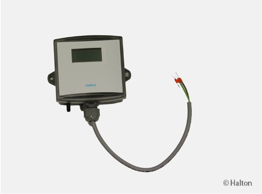
![]()
Fig.5. Halton Vita VHR diffuser with the Halton HDP-PE differential pressure transmitter
- For information on the pressure transmitter, see Accessories.
- For information on the order code, see Order code.
- For information on filters, see Filters.
Note: Filters need to be ordered separately.
Structure and materials
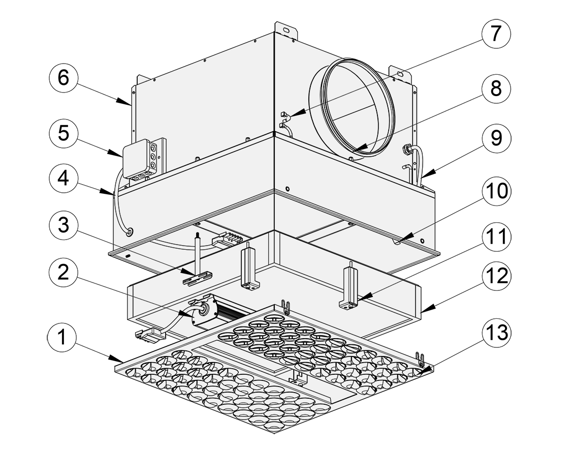
Fig.6. Structure of Halton Vita VHR
No. |
Part |
Description |
Note |
| 1 | Front panel | Galvannealed steel. White antibacterial epoxy polyester powder paint (RAL 9003/30%). Normal white powder paint (RAL 9003/30%) as option. |
Special colours available |
| 2 | Disinfection unit | Aluminium, glass. IP 44 | – |
| 3 | Disinfection unit brackets | Acid-proof steel and copper pipe. White antibacterial epoxy polyester powder paint (RAL 9003/30%). |
– |
| 4 | Disinfection unit power cable | 5×1.0 MSK | – |
| 5 | Junction box | Plastic (polypropylene). IP65. | – |
| 6 | Casing | Galvannealed steel. Stainless steel as option. With galvannealed steel: White antibacterial epoxy polyester powder paint (RAL 9003/30%). Normal white powder paint (RAL 9003/30%) as option. |
Special colours available |
| 7 | Pressure measurement ports | Polyurethane | – |
| 8 | Duct seal gasket | Rubber | – |
| 9 | Test probes | PVC hoses | – |
| 10 | Filter springs | Stainless steel | – |
| 11 | Filter brackets | Acid-proof steel | – |
| 12 | Filter | Fibreglass paper, aluminium frame, and a PUR gasket. | Filters need to be ordered separately. |
| 13 | Nozzle | Plastic (polyacetal) | – |
Dimensions and weight
Halton Vita VHR 600×600 mm
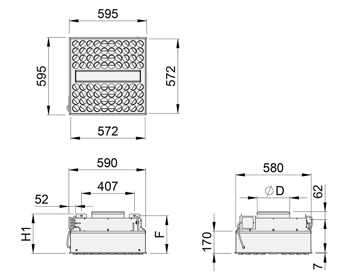
Fig.7. Halton Vita VHR 600×600 with top circular duct connection
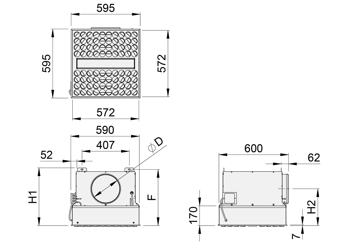
Fig.8. Halton Vita VHR 600×600 with side circular duct connection
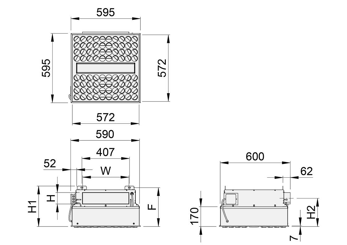
Fig.9. Halton Vita VHR 600×600 with side rectangulaer duct connection
Duct
|
ØD |
W |
H |
H1 |
H2 |
F |
Weight [kg], with disinfection units and filters |
| Top | 249 | – | – | 302 | – | 288 | 18.3 |
| Top | 314 | – | – | 302 | – | 288 | 18.3 |
| Side | 249 | – | – | 497 | 317 | 483 | 21.3 |
| Side | 314 | – | – | 562 | 350 | 548 | 22.3 |
| Side | – | 398 | 98 | 347 | 242 | 333 | 19.3 |
| Side | – | 398 | 148 | 397 | 267 | 383 | 19.8 |
Halton Vita VHR 1200×600 mm
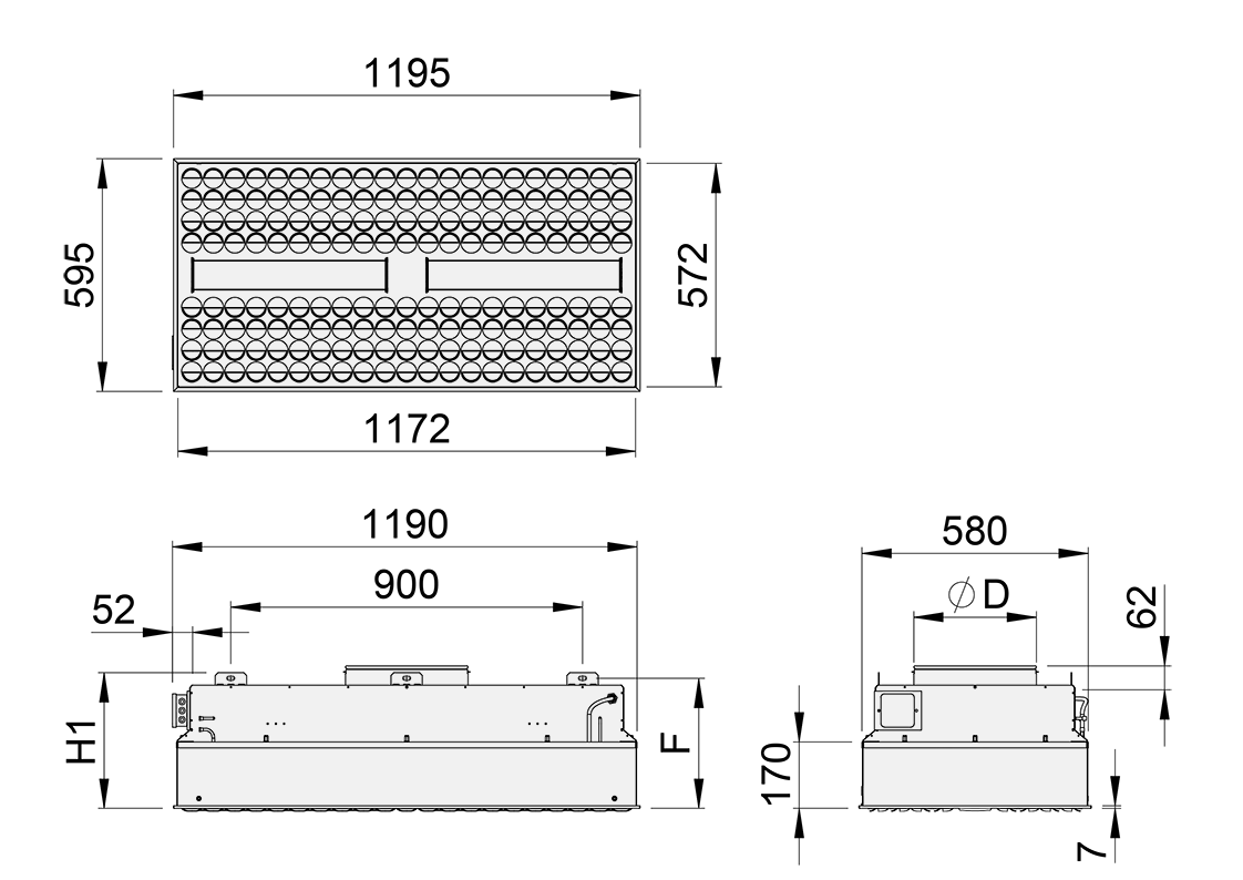
Fig.10. Halton Vita VHR 1200×600 with top circular duct connection
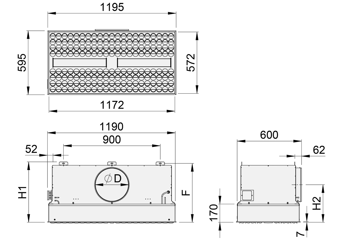
Fig.11. Halton Vita VHR 1200×600 with side circular duct connection
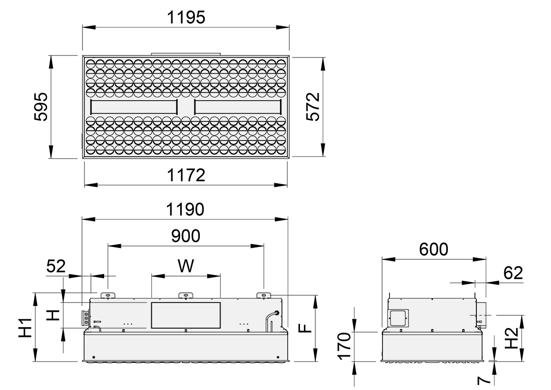
Fig. 12. Halton Vita VHR 1200×600 with side rectangular duct connection
Duct
|
ØD |
W |
H |
H1 |
H2 |
F |
Weight [kg], with disinfection units and filters |
| Top | 314 | – | – | 347 | – | 333 | 37.7 |
| Top | 399 | – | – | 347 | – | 333 | 37.7 |
| Side | 314 | – | – | 562 | 350 | 548 | 39.7 |
| Side | 399 | – | – | 647 | 392 | 633 | 45.7 |
| Side | – | 398 | 148 | 397 | 267 | 383 | 39.7 |
| Side | – | 598 | 198 | 447 | 292 | 433 | 40.7 |
Specification
- A diffuser with a HEPA filter for spaces where high cleanliness levels are required.
- Radial, swirl or low turbulent airflow pattern.
- Suitable for supply and exhaust ventilation.
- Installed flush to the ceiling or a wall.
Structure
- Unit size 600×600 mm or 1200×600 mm.
- Air supply through adjustable nozzles or a perforated front panel.
- The lockable nozzles ensure that the setting of the nozzles remains unchanged during cleaning.
- A smooth internal surface that enables easy cleaning.
- Easy filter change through the front panel.
- Test probe for measuring particle concentration before the filter.
- Test probe for measuring the filter pressure loss.
- Differential pressure transmitter to indicate the filter pressure loss.
- Disinfection unit with blue light and white light LED elements. Blue light is for disinfection and white light is for general lighting.
- Used with an HEPA filter that has an aluminium frame and a PUR gasket according to EN 1822, including an
individual test certificate.
Material
- Casing and front panel manufactured from galvannealed steel.
- Antibacterial epoxy-polyester powder paint finishing to prevent microbial growth.
- Nozzles manufactured from plastic (polyacetal).
Packaging and identification
- The visible surface of the product is protected by a removable plastic coating. The duct connection remains sealed during transport.
- The product is packed on a pallet.
- The product is identified by a serial number printed on labels attached both to the product and the package.
Installation
The diffuser is connected to the duct by screwing or by riveting. The duct connection spigot is equipped with a seal gasket. The diffuser can be installed in the following ways:
- Flush with the ceiling (hung from the ceiling with M6 drop rods using fixing brackets)
- Flush with the wall
Note: When installing the unit, be careful not to drill any holes into the casing. If the casing is damaged, unfiltered air may leak.
The internal cabling of disinfection units is done at the factory. The external cabling is connected to the junction box at the site.
The unit should be cleaned on the inside before filter installation.
Filter integrity testing should be performed after filter installation.
Commisioning
The nozzles are preset to four directions at the factory.
If needed, the nozzles can be manually adjusted on site to create the desired airflow pattern. The nozzles can be adjusted in 15-degree intervals.
Maintenance
The required maintenance tasks include changing the filter and cleaning the supply air unit.
Filter
To ensure that the air quality meets the requirements, the HEPA filter must be checked frequently and, if needed, the filter must be replaced. The maintenance frequency of a filter depends on the air cleanliness of the supply air and room air.
The filter must be immediately replaced in the following cases:
- The final differential pressure has been reached.
- The filter is damaged.
- There are micro-organisms, fungal spores, or odours present in the filter.
Diffuser
The unit can be cleaned using disinfectants. The front panel can be removed and cleaned in a washing machine (water temperature < 95°C). The lockable nozzles ensure that the setting of the nozzles remains unchanged during cleaning.
Be careful not to wet the filters. Dampening the filter media will permanently decrease the filter efficiency.
For cleaning frequency, follow the maintenance schedule of the building.
Filters
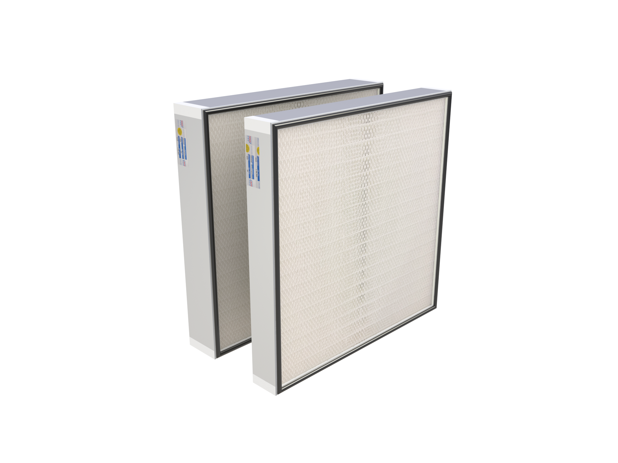
Fig.19. HEPA filters
Description
High efficiency particulate air (HEPA) filters are widely applied in cleanrooms where high air quality standards are
essential.
Note: Filters need to be ordered separately.
Technical data of HEPA filters
Filters compatible with the Halton Vita VHR HEPA diffuser are available in classes E10, H13 and H14 (European Standard EN 1822-1:2009) for standard and high airflow. The available filter depths are 68, 90 mm. All filters have a polyurethane (PUR) foam gasket.
Operating range:
- Temperature max. 70 °C
- Humidity max. 90 %
- Final pressure drop max. 500 Pa
Dimensions WxHxD [mm] |
Filter class |
Weight [kg] |
Order code |
| 525x525x68 | H14, H13, E10 | 3.1 | AF-H14/H13/E10-AL-525*525*68-PUR |
| 525x525x90 | H14, H13, E10 | 3.3 | AF-H14/H13/E10-AL-525*525*90-PUR |
| 1125x525x68 | H14, H13, E10 | 9.5 | AF-H14/H13/E10-AL-1125*525*68-PUR |
| 1125x525x90 | H14, H13, E10 | 9.7 | AF-H14/H13/E10-AL-1125*525*90-PUR |
Filter selections in Halton HIT Design
To get the right performance data (dpt and Lp(A)) to diagrams and CAD export files, in Halton HIT Design, select “Accessories”, then select the desired values for the following:
- Duct connection location
- Duct connection size
- Filtering type/bracket height
Filter class / Filter depth |
Filter selection code |
| H14 / 68 mm | A1 |
| H14 / 90 mm | A2 |
| H13 / 68 mm | B1 |
| H13 / 90 mm | B2 |
| E10 / 68 mm | C1 |
| E10 / 90 mm | C2 |
Accessories
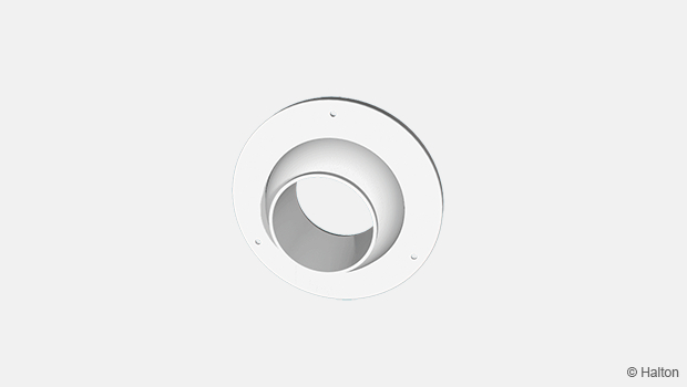
Halton HDP-PE
The Halton HDP-PE differential pressure sensor is a pressure-measuring device, used to measure differential pressures in the duct.
Description
- The pressure sensor gives an accurate measurement of the airflow.
- The IP54 casing ensures that the unit can be used also in dusty and humid environments.
- The proper range of measurement can be selected at commissioning. The outputs are directly proportional to
the pressure differences between the + and – inlets. - The connections to the detected process are made by using plastic tubing (⌀ 6/4 mm).
- The software compensates the zero-point drift for the transmitter by making automatic calibrations every 5
minutes, so that manual recalibration is not normally required. - The influence of process disturbances can be filtered by increasing the time constant.
- The sensor can be used for measurement in polluted air.
- The PEL can be integrated in a fast system due to its standard time constant of 0.5 s.
Technical data
Feature |
Description |
| Output signals |
|
| Power supply |
|
| Power consumption |
|
| Temperature drift of range, typical | < 0.05% / K |
| Error at zero pressure |
|
| Inaccuracy | < ± 0.5 Pa + ± 1% of reading (at 25°C) |
| Operating temperature | 0…45°C |
| Max. static / over pressure | 25 kPa |
| Housing | IP54 |
Table 2. Technical data for Halton HDP-PE differential pressure sensor
Pa |
Drift |
| 0… 100 | ± 50 Pa |
| 0… 200 | ± 100 Pa |
| 0… 500 | ± 250 Pa |
| 0… 1000 | ± 500 Pa |
Table 3. Measuring ranges for Halton HDP-PE differential pressure sensor
Note: The proper measuring ranges chosen at commissioning: ± ranges (s4 = open) 5 V / 12 mA = 0 Pa.
Installation (ranges, coding, wiring)

Order code
VHR-M-A-FP; LC-C-D-MA-CO-IO-DF-FA-PT-ZT
| Main options | |
| M = Model | |
| A | Supply air unit with blue light disinfection |
| B | Exhaust air unit with blue light disinfection |
| C | Supply air unit with option to add blue light disinfection later |
| D | Exhaust air unit with option to add blue light disinfection later |
| A = Size [mm] | |
| 600 | 600×600 |
| 1200 | 1200×600 |
| FP = Front panel | |
| NO | Nozzle |
| PE | Perforated |
| Other options and accessories | |
| LC = Light controller type | |
| NA | Not assigned |
| L5 | DALI |
| L6 | Relay, On/Off |
| C = Location of duct connection | |
| S | Side (circular and rectangular) |
| T | Top (circular only) |
| D = Size of duct connection (mm) | |
| Circular | |
| C | 250 |
| D | 315 |
| E | 400 |
| Rectangular | |
| G | 400×100 |
| H | 400×150 |
| I | 600×200 |
| MA = Material | |
| GE | Galvanaeled steel |
| IO = Installation options for ceiling types | |
| NA | Not assigned |
| DF = Diffuser delivered with front panel | |
| Y | Yes |
| N | No |
| FA = Front panel attached to unit | |
| Y | Yes |
| N | No |
| FT = Filtering type/bracket height (filter to be ordered separately) | |
| A2 | H14/90 mm |
| A1 | H14/68 mm |
| B1 | H13/68 mm |
| B2 | H13/90 mm |
| C1 | E10/68 mm |
| C2 | E10/90 mm |
| PT = Differential pressure transmitter | |
| NA | Not assigned |
| P1 | HDP-PE |
| CO = Colour | |
| SA | Signal white (antibacterial, RAL 9003) |
| SW | Signal white (RAL 9003) |
| X | Special colour (RAL xxxx) |
| ZT = Tailored product | |
| N | No |
| Y | Yes (ETO) |
Order code example
VHR-A-600-NO; LC=NA, C=S, D=F, MA=GE, CO=SW, IO=NA, DF=Y, FA=Y, PT=NA, ZT=N
Downloads
"*" indicates required fields
Halton APL – Jet air diffuser
product
Halton APS – Jet air diffuser
product
Halton BCF – Floor diffuser
product
Halton CAR – Conical diffuser
product
Halton DAC – Square diffuser
product
Halton DCS – Modular diffuser
product
Halton DFA – Square conical diffuser
product
Halton DFB – Conical diffuser
product
Halton DRV – Multi-nozzle terminal unit
product
Halton IAO – Jet nozzle diffuser
product
Halton Jaz JCC – Diffuser
product
Halton Jaz JDA – Diffuser with side slot
product
Halton Jaz JDB – Diffuser with side slot
product
Halton Jaz JDS – Variable air volume diffuser unit (VAV)
product
Halton Jaz JMC – Nozzle diffuser
product
Halton Jaz JRC – Perforated diffuser
product
Halton Jaz JRP – Swirl diffuser
product
Halton Jaz JSC – Nozzle diffuser
product
Halton Jaz JTH – Swirl diffuser
product
Halton Jaz JWC – Swirl diffuser
product