Product / TCV
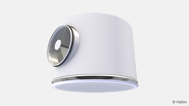
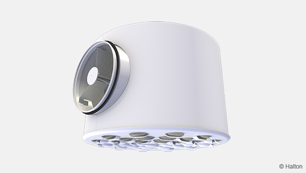
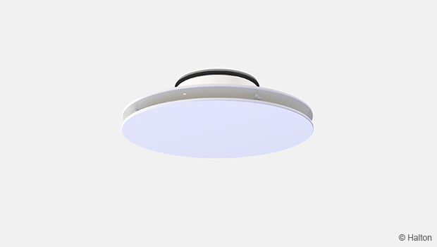
Halton TCV – Terminal diffuser
Circular and compact in design for free installation without suspended ceiling
- Effective sound attenuation
- Deflector for the direction of flow pattern
Overview
- Horisontal air supply
- Suitable for supply and exhaust
- Integrated circular balancing plenum with measurement and adjustment functions
- Effective sound attenuation
- Circular duct connection with gasket
- Deflector for direction of flow pattern
- Detachable front plate enables cleaning of the terminal unit and ductwork
Quick selection
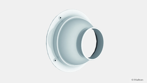
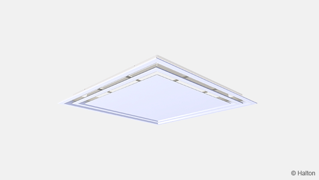
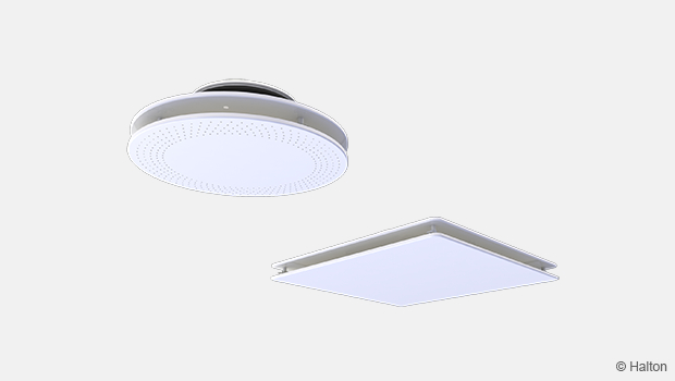
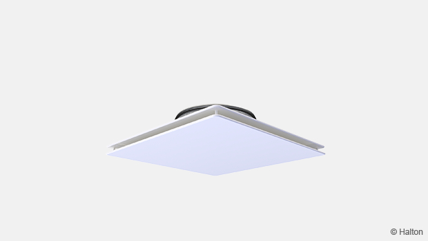
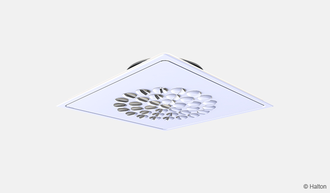
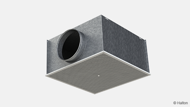
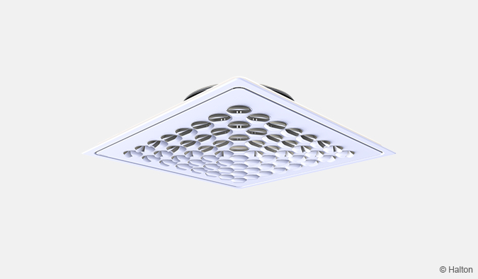
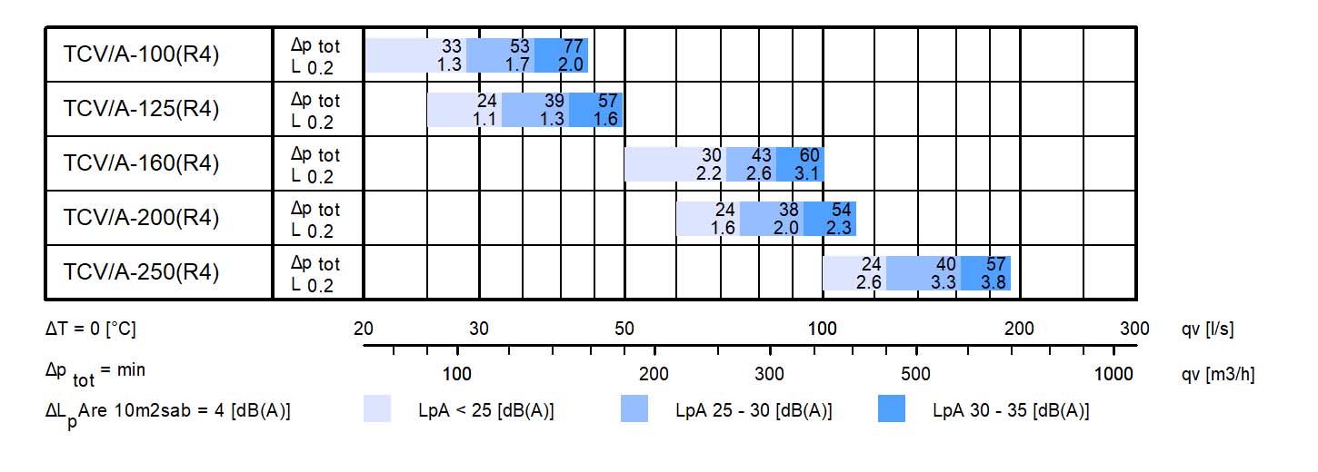 Fig.1. Halton TCV with MSM module, supply.
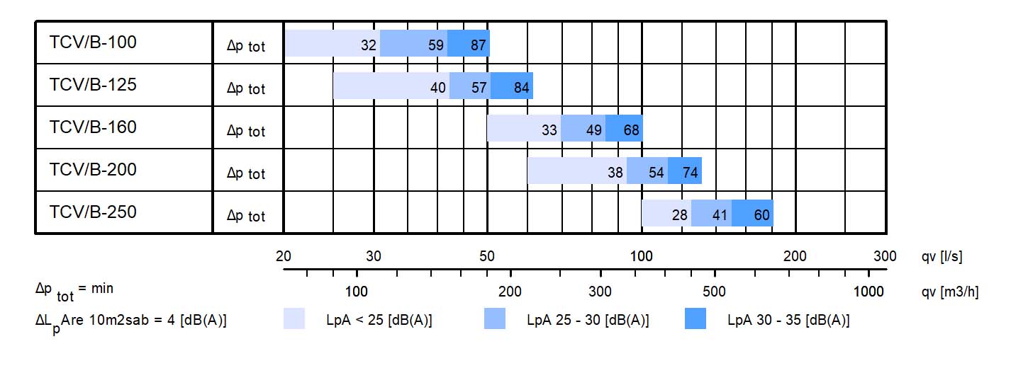
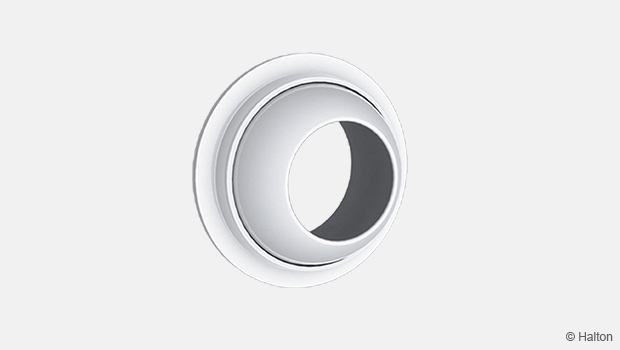
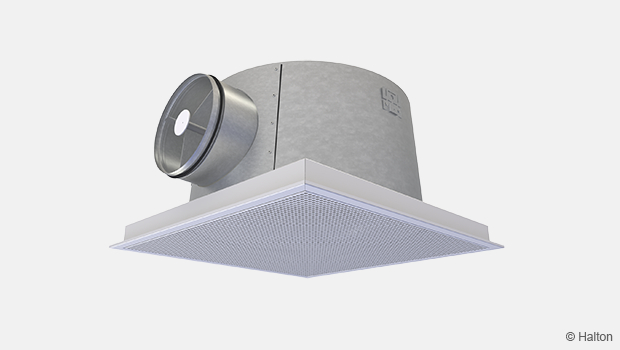
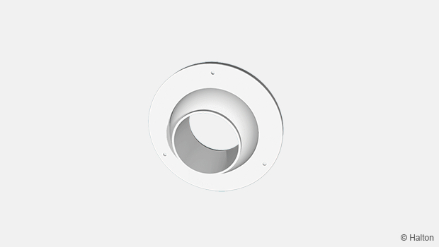
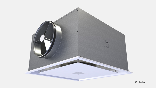
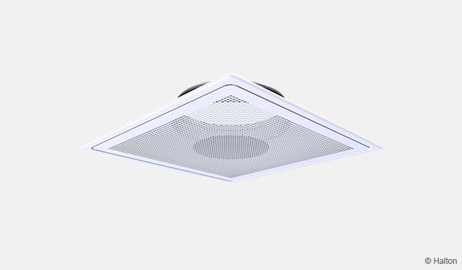
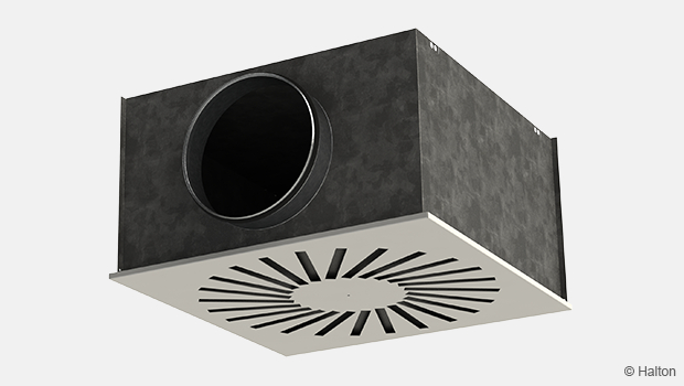
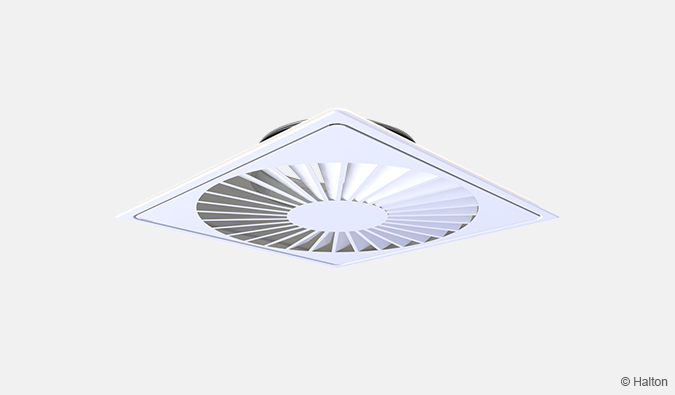
Fig.2. Halton TCV with MEM module, exhaust.
Dimensions
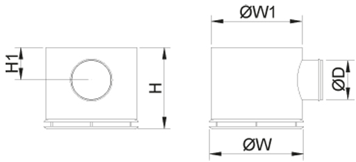
| NS | ØW | ØW1 | H | H1 | ØD |
| 100 | 300 | 289 | 258 | 93 | 99 |
| 125 | 300 | 289 | 258 | 103 | 124 |
| 160 | 450 | 439 | 294 | 121 | 159 |
| 200 | 450 | 439 | 318 | 138 | 199 |
| 250 | 600 | 589 | 377 | 174 | 249 |
Weight (kg)
| NS | Weight |
| 100 | 3.90 |
| 125 | 3.86 |
| 160 | 7.49 |
| 200 | 7.72 |
| 250 | 12.39 |
Material
| Part | Material | Note |
| Upper plate | Steel | |
| Front panel | Perforated steel | |
| Deflection panels |
Steel | |
| Plenum | Galvanised steel | |
| Attenuation material |
Polyester fibre | Surfaces protection layer |
| Spigot | Galvanised steel | |
| Gasket | Rubber compound | |
| Finishing | Painted White (RAL 9003) |
Special colours available |
Function
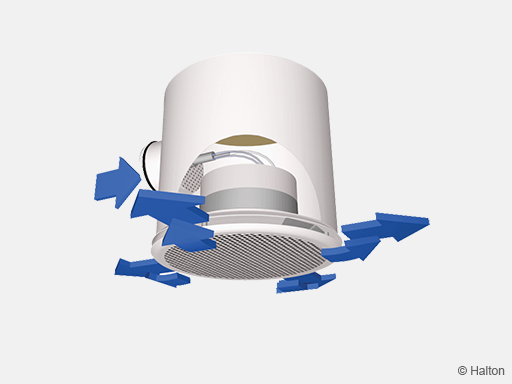
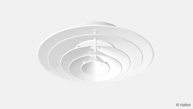
Air is supplied into the space through the side slots and front panel of the diffuser and mixed with the room air outside the diffuser.
The throw pattern can be deflected in different (1, 2, 3 and 4) directions with the deflection panels.
Recommended maximum air temperature difference between supply and room air in cooling situations is 10 °C.
Installation
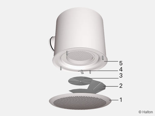
Code description
1. Front panel
2. Deflector panel
3. Deflector plate
4. Spring
5. Plenum
The terminal unit is connected directly to the duct by screwing or riveting. The desired flow pattern is selected with the deflector panels during installation.
It is recommended that the minimum safety distance before the terminal unit is 3xD.
In an exhaust application neither deflector panels nor deflector plate are used.
Adjustment
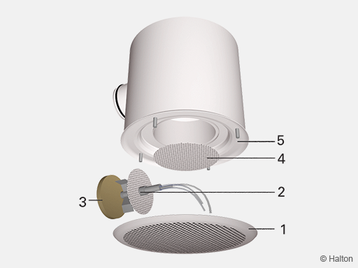
Code description
1. Front panel
2. . Measurement and adjustment module
3. Pressure test plug
4. Equalisation plate
5. Plenum
The supply volume flow rate is determined using the measurement and adjustment module MSM.
Open the front panel and equalisation plate, pass the tubes and control spindle through the equalisation plate and side slot of the diffuser.
Replace the front panel.
Measure the differential pressure using a manometer. The airflow rate is calculated using the formula below.
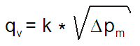
Adjust the airflow rate by rotating the control spindle until the desired setting is achieved.
Lock the damper position with a screw.
Reassemble the tubes and spindle into the plenum and replace the diffuser front panel.
The exhaust flow rate is determined by using the separate measurement module located in the equalisation plate.
The k- factor for installations with different safety distances (D = duct diameter)
Supply air
| ØD | (>8xD) | min 3xD |
| 100 | 6.0 | 8.5 |
| 125 | 10.0 | 13.0 |
| 160 | 17.1 | 22.8 |
| 200 | 27.5 | 32.1 |
| 315 | 47.9 | 55.5 |
Exhaust air
| ØD | k |
| 100 | 8.7 |
| 125 | 21.6 |
| 160 | 21.6 |
| 200 | 53.1 |
| 250 | 53.1 |
Servicing
Open the front panel of the diffuser and clean the parts by wiping with a damp cloth.
Remove the equalisation plate, and measurement and adjustment module by gently pulling the shaft (not the control spindle or measurement tubes!).
Wipe the parts with a damp cloth, instead of immersing in water.
Reassemble the equalisation plate, and measurement and adjustment module by pushing the shaft back into place until the unit meets the stopper.
Push the front panel back into place so that the springs lock.
Specification
The diffuser and plenum is made of epoxy-painted steel with a white (RAL 9003) colour.
The diffuser difsfuse the suspply air into the space through the side slot and perforated front panel, ensuring a high mixing rate.
Flow pattern of the diffuser i adjustable in a 1, 2, 3 or 4-way direction by shaping the deflector.
The diffuser is integrated to a balancing plenum equipped with a measurement and adjustment module.
The diffuser has a detachable perforated front panel in order to provide access to the measurement and adjustment module in the plenum.
The balancing plenum has a spigot equipped with integral gasket for airtight duct connection.
Order code
TCV-S-D, CO-ZT
| Main options | |
| S = Construction | |
| A | Supply air with MSM module |
| B | Exhaust air with MEM module |
| D = Connection size [mm] | 100, 125, 160, 200, 250 |
| Other options and accessories | |
| CO = Colour | |
| SW | White (RAL 9003) |
| X | Special colour (RAL xxxx) |
| ZT = Tailored product | |
| N | No |
| Y | Yes (ETO) |
Order code example
TCV-A-100, CO=SW,ZT=N
Downloads
"*" indicates required fields
Halton APL – Jet air diffuser
product
Halton APS – Jet air diffuser
product
Halton BCF – Floor diffuser
product
Halton CAR – Conical diffuser
product
Halton DAC – Square diffuser
product
Halton DCS – Modular diffuser
product
Halton DFA – Square conical diffuser
product
Halton DFB – Conical diffuser
product
Halton DRV – Multi-nozzle terminal unit
product
Halton IAO – Jet nozzle diffuser
product
Halton Jaz JCC – Diffuser
product
Halton Jaz JDA – Diffuser with side slot
product
Halton Jaz JDB – Diffuser with side slot
product
Halton Jaz JDS – Variable air volume diffuser unit (VAV)
product
Halton Jaz JMC – Nozzle diffuser
product
Halton Jaz JRC – Perforated diffuser
product
Halton Jaz JRP – Swirl diffuser
product
Halton Jaz JSC – Nozzle diffuser
product
Halton Jaz JTH – Swirl diffuser
product
Halton Jaz JWC – Swirl diffuser
product