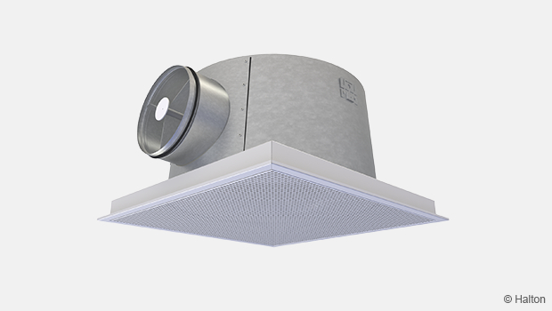
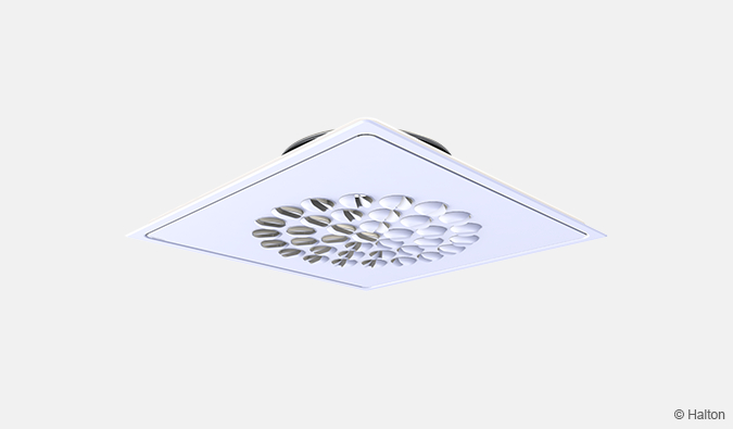
Product / TSA
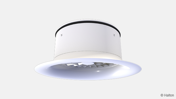
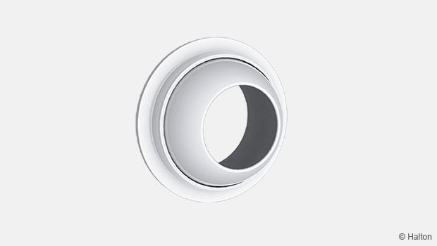
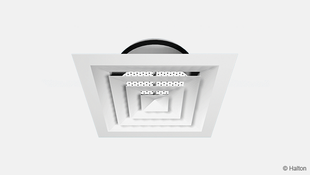
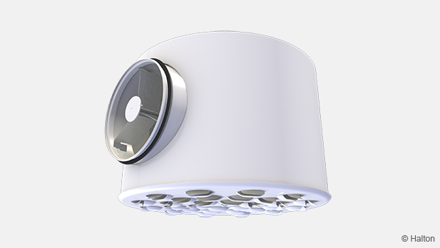
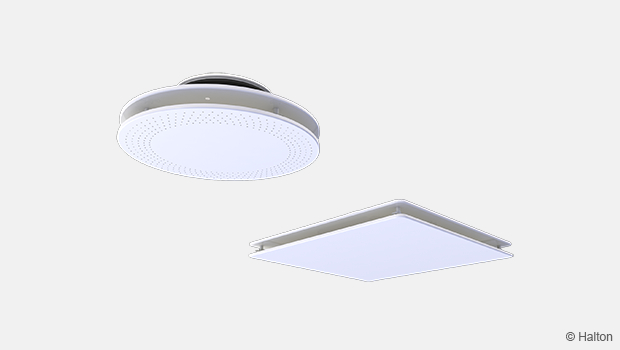
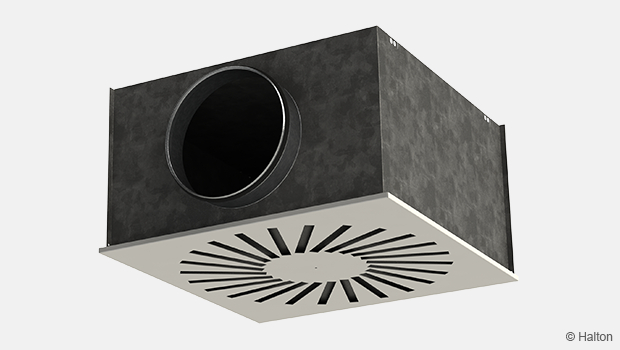
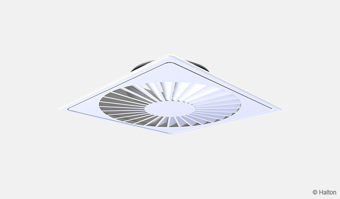
Halton TSA – Swirl diffuser
Ideal for high spaces.
- Specially designed for large and high spaces
- Supply air pattern can be adjusted either manually or controlled by actuator
Overview
- Horisontal radial or vertical compact swirl jet air supply
- Suitable for heating and cooling applications
- Specially designed for large and high spaces
- Supply air pattern can be adjusted either manually or controlled by actuator
- High induction swirl jet ensures efficient mixing and fast reduction of air velocity
- Installation using plenum or directly to ductwork
Accessories
- Plenum options with measurement and adjustment functions
- Actuator (with 24 VAC power supply and proportional 0…10 VDC control signal or alternatively self-actuating wax-bulb) for the direction of airflow pattern
Quick selection
Values with adjustment module (MSM) fully open.
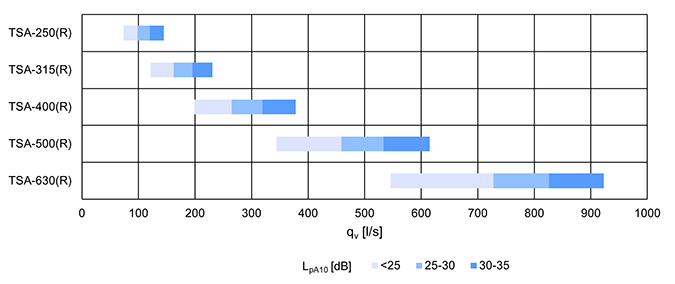
Fig. 1. Quick selection for diffuser with radial jet, unit l/s
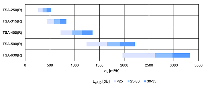
Fig. 2. Quick selection for diffuser with radial jet, unit m3/h
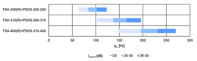
Fig. 3. Quick selection for diffuser and plenum with radial jet, unit l/s
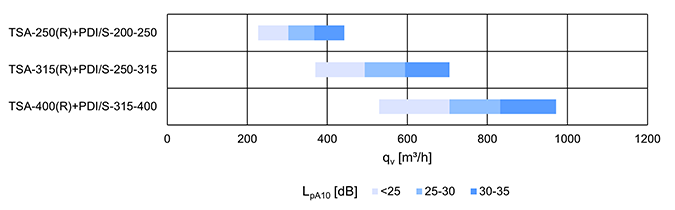
Fig. 4. Quick selection for diffuser and plenum with radial jet, unit m3/h
Dimensions and weight
Halton TSA, manually operated (MO=NA)
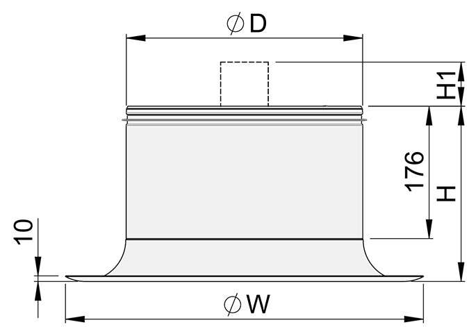
| TSA [mm] |
ØW [mm] |
H [mm] |
H1 [mm] |
ØD [mm] |
Weight [kg] |
|||
| MO=M2* | MO=M3* | MO=NA* | MO=M2* | MO=M3* | ||||
| 250 | 382 | 221 | 209 | 52 | 249 | 3.7 | 4.2 | 4.1 |
| 315 | 475 | 233 | 226 | 69 | 314 | 4.8 | 5.3 | 5.2 |
| 400 | 593 | 246 | 240 | 83 | 399 | 7.3 | 7.8 | 7.7 |
| 500 | 735 | 264 | 235 | 78 | 499 | 9.6 | 10.1 | 10.0 |
| 630 | 917 | 286 | 238 | 81 | 629 | 11.6 | 12.1 | 12.0 |
* Manually operated (MO = NA), Electrical actuator (MO=M2), Wax-bulb actuator (MO=M3)
Halton TSA with Halton Pop PDI plenum
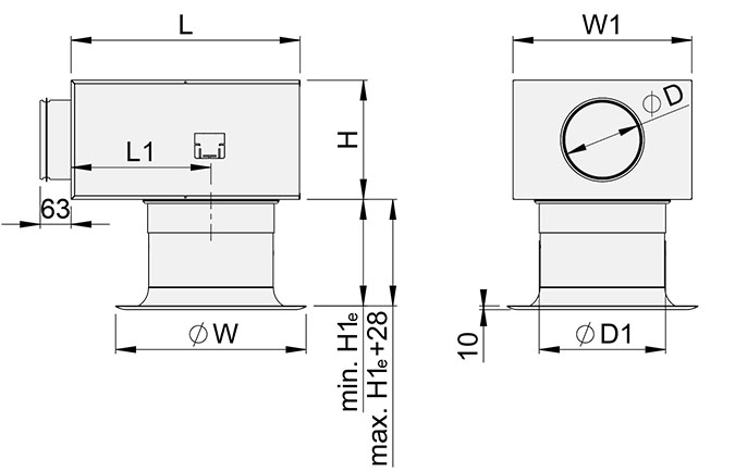
Fig. 5. Halton TSA with Halton Pop PDI plenum, externally positioned connection spigot
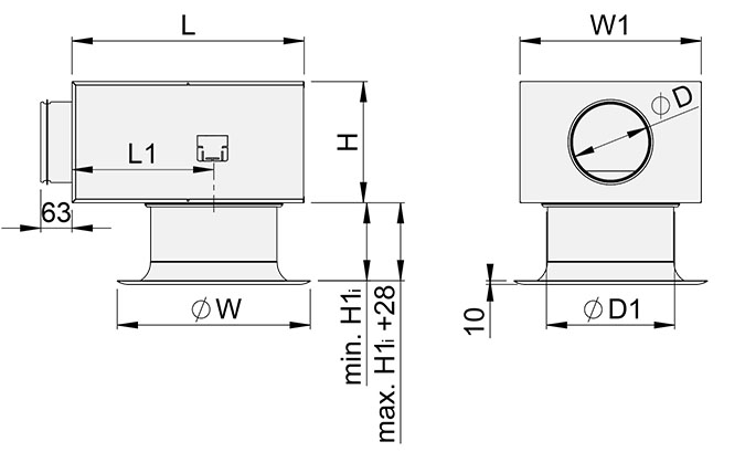
Fig. 6. Halton TSA with Halton Pop PDI plenum, internally positioned connection spigot
| TSA | W [mm] |
PDI [mm] |
ØD [mm] |
ØD1 [mm] |
L [mm] |
W1 [mm] |
H [mm] |
H1e [mm] |
H1i [mm] |
L1 [mm] |
Weight [kg] |
| 250 | 382 | 200-250 | 199 | 252 | 458 | 358 | 239 | 211 | 151 | 280 | 8.6 |
| 382 | 250-250 | 249 | 252 | 520 | 480 | 359 | 211 | 151 | 280 | 11.9 | |
| 315 | 475 | 250-315 | 249 | 317 | 520 | 480 | 359 | 223 | 163 | 280 | 12.8 |
| 475 | 315-315 | 314 | 317 | 520 | 480 | 359 | 223 | 163 | 280 | 13.0 | |
| 400 | 593 | 315-400 | 314 | 402 | 520 | 480 | 359 | 236 | 176 | 280 | 15.3 |
Material
| Part | Description | Note |
| Casing | Steel | – |
| Deflector ring or cylinder | Steel | – |
| Front vane panel | Steel | – |
| Knob | Plastic | Colour options: White or black |
| Finishing | Painted, white (RAL 9003/30%) |
Special colours available |
Product models
Halton TSA with electric actuator (MO=M2)
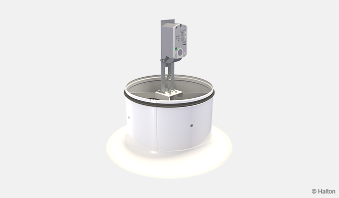
Fig.7. Halton TSA with Siemens GDB161.2E/HA actuator with 24 VAC power supply and proportional 0…10 VDC control signal
Halton TSA with wax-bulb actuator (MO=M3)
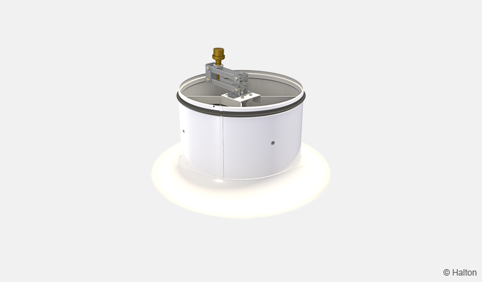
Fig.8. Halton TSA equipped with a wax-bulb actuator
- Work without any power supply.
- The cylinder position changes according to the temperature of supply air.
- The temperature range of the wax-bulb actuator is about 20 °C to 27 °C.
- The time taken to change from radial to compact jet (or the other way around) is 10 – 20 minutes.
- When warm air is supplied the piston of the wax bulb actuator keeps moving until the TSA supply air pattern is vertical. When cold air is supplied, the Halton TSA supply air pattern is changed back to horizontal by means of a spring.
Operating principle
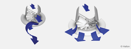
Compact jet Radial Jet
The Halton TSA is a high induction swirl diffuser with an adjustable flow pattern. The horizontal radial swirl jet is used mainly in cooling applications that use cool supply air or for ventilation with isothermal supply air.
The vertical compact swirl jet with warm supply air is used in heating applications.
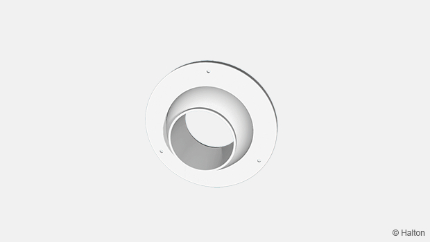
Adjustment of the supply air pattern is effected by moving the internal adjustment element (cylinder).
It is also possible to change from cooling mode to heating mode by adjusting the flow pattern using an electric or wax bulb actuator.
The recommended maximum temperature differences between room and supply air temperatures are +15 °C for heating and -15 °C for cooling applications.
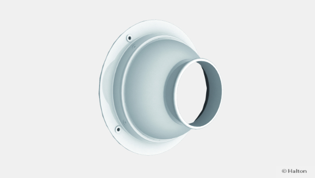
Installation
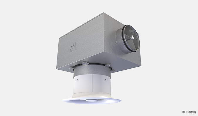
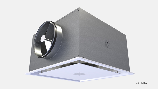
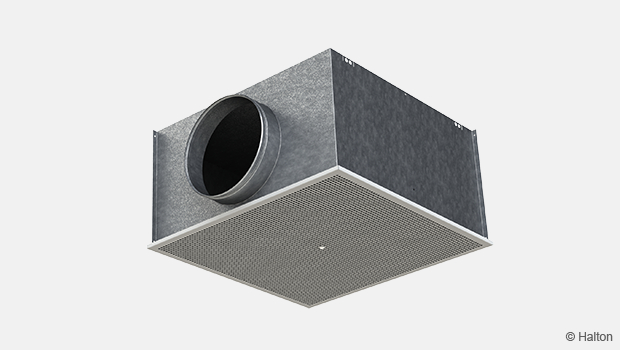
Fig. 9. Halton TSA diffuser connected to a Halton Pop PDI plenum
The diffuser is connected usually to balancing plenum Halton Pop PDI. Alternatively, it can be connected direct to the duct by riveting or screwing. In that case, minimum safety distance to the next T-branch or curve is three times the duct diameter (3xD).
The front vane panel can be reattached
- Remove the screws through the front vane panel (sizes 250 and 315) or between the cylinder and casing (sizes 400, 500 and 630), turn and hold the front vane panel to remove.
Take care during installation to ensure that the cylinder can move freely and that the actuator has adequate installation space. There should be at least 50 mm clearance space above the top of the device when the cylinder is in the lowest position. The connection and fixing rivets or screws may not be located more than 50 mm below the upper edge of the diffuser.
Wiring and DIL switches (MO=M2)
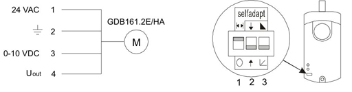
DIL switches:
1. Automatic adaptation of limited movement length to 0-10 VDC control signal
2. Direction of shaft movement based on 0-10 VDC control signal
3. Feedback signal
Commissioning
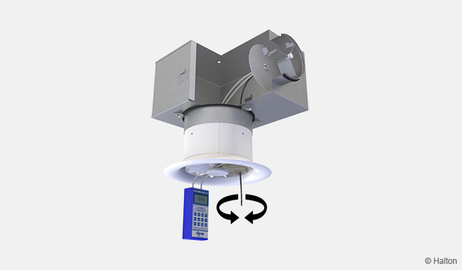
Fig. 8. Adjustment of airflow of diffuser and plenum combination
Airflow control
The diffuser itself has no airflow adjustment. To adjust and measure the supply airflow rate, the diffuser shall be combined with Halton Pop PDI balancing plenum with measurement and adjustment module MSM. In case of exhaust air, use of adjustment module MEM is recommended. It is not possible to measure exhaust airflow rate with adjustment module MEM.
Open the front plate and pass the tubes and control spindle through the front panel (Fig. 8.). Replace the front panel. Measure the differential pressure with a manometer. The flow rate is calculated using the formula below:
![]()
where
- qv Airflow rate [l/s] or [m3/h]
- ∆pm Measured pressure [Pa]
- k The k factor (see the table below)
Adjust the airflow rate by rotating the control spindle until the desired airflow rate (pressure difference) is achieved.
Set the tubes and spindle back into the plenum. Damper position can be locked with a knurled head screw of the adjuster.
| Duct connection (PDI) | k factor of MSM adjuster, opening >0 [l/s] | |
| > 8D | Min. 3D | |
| 100 | 5.7 | 7.5 |
| 125 | 9.6 | 12.6 |
| 160 | 16.4 | 21.9 |
| 200 | 26.3 | 31.0 |
| 250 | 47.1 | 51.5 |
| 315 | 78.8 | – |
| Duct connection (PDI) | k factor of MSM adjuster, opening >0 [m3/h] | |
| > 8D | Min. 3D | |
| 100 | 20.6 | 27.0 |
| 125 | 34.4 | 45.4 |
| 160 | 59.0 | 78.8 |
| 200 | 94.8 | 111.6 |
| 250 | 169.5 | 185.4 |
| 315 | 283.6 | – |
Throw pattern adjustment
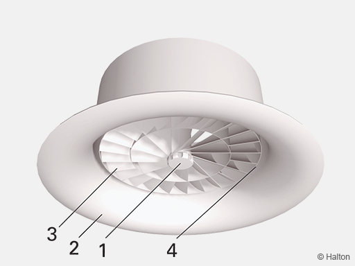
Key
1. Control knob
2. Casing
3. Front vane panel
4. Cylinder
The supply air jet is adjusted by changing the position of the cylinder. When you turn the control knob clockwise the throw pattern is changes from radial to compact.
Maintenance
Remove the front vane panel and clean the diffuser by wiping it with a damp cloth, instead of immersing it in water.
Option with balancing plenum
Remove the measurement and adjustment module by pulling gently the shaft; (not the control spindle or measurement tubes!).
Wipe the parts with a damp cloth, instead of immersing them in water.
Remount the measurement and adjustment module by pushing the shaft until the module meets the stopper.
Specification
The diffuser consists of a frame with fixed internal profiled vane rings and a movable cylinder for throw pattern selection.
The front vane panel, the movable cylinder and the frame are made of powder painted steel, with a white (RAL 9003/30%) as standard colour.
The airflow pattern is adjustable automatically using an electrical or wax-bulb actuator, (in applications where both heating and cooling are required.)
Order code
TSA-D; CO-MO-ZT
| Main options | |
| D = Diffuser duct connection size [mm] | 250, 315, 400, 500, 630 |
| Other options and accessories | |
| CO = Colour | |
| SW | Signal white (RAL 9003) |
| X | Special colour (RAL xxxx) |
| MO = Actuator type | |
| NA | Not assigned |
| M2 | 24 VAC actuator, 0…10 VDC control signal |
| M3 | Wax-bulb actuator |
| ZT = Taylored product | |
| N | No |
| Y | Yes (ETO) |
| Sub products and accessories (ordered separately) | |
| Halton Pop PDI | Balancing plenum |
Order code example
TSA-250; CO=SW, MO=NA, ZT=N
Downloads
"*" indicates required fields
Halton APL – Jet air diffuser
product
Halton APS – Jet air diffuser
product
Halton BCF – Floor diffuser
product
Halton CAR – Conical diffuser
product
Halton DAC – Square diffuser
product
Halton DCS – Modular diffuser
product
Halton DFA – Square conical diffuser
product

Halton DFB – Conical diffuser
product
Halton DRV – Multi-nozzle terminal unit
product
Halton IAO – Jet nozzle diffuser
product
Halton Jaz JCC – Diffuser
product
Halton Jaz JDA – Diffuser with side slot
product
Halton Jaz JDB – Diffuser with side slot
product
Halton Jaz JDS – Variable air volume diffuser unit (VAV)
product
Halton Jaz JMC – Nozzle diffuser
product
Halton Jaz JRC – Perforated diffuser
product
Halton Jaz JRP – Swirl diffuser
product
Halton Jaz JSC – Nozzle diffuser
product
Halton Jaz JTH – Swirl diffuser
product
Halton Jaz JWC – Swirl diffuser
product