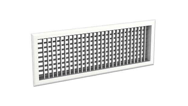
Product / WDD
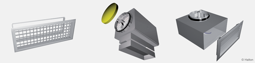
Overview
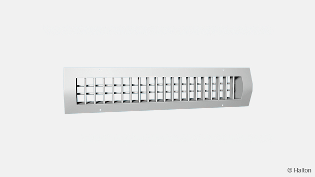
- For cooling and heating applications; suitable also for exhaust
- Adjustable vertical and horizontal vanes
- Aluminium construction
Accessories
- Wax-bulb actuator for directing the supply air jet in heating operation
- Airflow adjustment damper
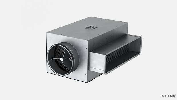
- Plenum options with measurement and adjustment functions
- Installation frame
Dimensions
Halton WDD, rounded frame (R)

| LxH | L1 | L2 | H1 | H2 |
| 200×100 | 226 | 176 | 126 | 76 |
| 250×100 | 276 | 226 | 126 | 76 |
| 300×100 | 326 | 276 | 126 | 76 |
| 300×150 | 326 | 276 | 176 | 126 |
| 400×150 | 426 | 376 | 176 | 126 |
| 400×200 | 426 | 376 | 226 | 176 |
| 500×200 | 526 | 476 | 226 | 176 |
| 600×200 | 626 | 576 | 226 | 176 |
| 800×200 | 826 | 776 | 226 | 176 |
| 1000×200 | 1026 | 976 | 226 | 176 |
| 600×300 | 626 | 576 | 326 | 276 |
| 800×300 | 826 | 776 | 326 | 276 |
| 1000×300 | 1026 | 976 | 326 | 276 |
| 1000×400 | 1026 | 976 | 426 | 376 |
| 1200×400 | 1226 | 1176 | 426 | 376 |
Halton WDD, flat frame 22 mm (F)

| LxH | L1 | L2 | H1 | H2 |
| 200×100 | 220 | 176 | 120 | 76 |
| 250×100 | 270 | 226 | 120 | 76 |
| 300×100 | 320 | 276 | 120 | 76 |
| 300×150 | 320 | 276 | 170 | 126 |
| 400×150 | 420 | 376 | 170 | 126 |
| 400×200 | 420 | 376 | 220 | 176 |
| 500×200 | 520 | 476 | 220 | 176 |
| 600×200 | 620 | 576 | 220 | 176 |
| 800×200 | 820 | 776 | 220 | 176 |
| 1000×200 | 1020 | 976 | 220 | 176 |
| 600×300 | 620 | 576 | 320 | 276 |
| 800×300 | 820 | 776 | 320 | 276 |
| 1000×300 | 1020 | 976 | 320 | 276 |
| 1000×400 | 1020 | 976 | 420 | 376 |
| 1200×400 | 1220 | 1176 | 420 | 376 |
Halton WDD, flat frame 30 mm (F2)

| LxH | L1 | L2 | H1 | H2 |
| 200×100 | 236 | 176 | 136 | 76 |
| 250×100 | 286 | 226 | 136 | 76 |
| 300×100 | 336 | 276 | 136 | 76 |
| 300×150 | 336 | 276 | 186 | 126 |
| 400×150 | 436 | 376 | 186 | 126 |
| 400×200 | 436 | 376 | 236 | 176 |
| 500×200 | 536 | 476 | 236 | 176 |
| 600×200 | 636 | 576 | 236 | 176 |
| 800×200 | 836 | 776 | 236 | 176 |
| 1000×200 | 1036 | 976 | 236 | 176 |
| 600×300 | 636 | 576 | 336 | 276 |
| 800×300 | 836 | 776 | 336 | 276 |
| 1000×300 | 1036 | 976 | 336 | 276 |
| 1000×400 | 1036 | 976 | 436 | 376 |
| 1200×400 | 1236 | 1176 | 436 | 376 |
With OD (airflow adjustment damper) total depth is 48 mm + 45 mm.
Special dimensions
In addition to these standard sizes, other dimensions are available by special order.
The maximum size is 1500 mm x 600 mm (LxH).
Structure and materials

| No. | Part | Description | Note |
| 1 | Frame | Aluminium. Polyester-painted as white (RAL 9003/ 30% gloss), anodised or mill finished | Special colours available |
| 2 | Vanes | Aluminium. Polyester-painted as white (RAL 9003/30% gloss), anodised or mill finished | Special colours available |
The bevel angles of the outer frame have been welded so that the joints are almost invisible.
Features and options
| Category | Feature (order code) |
Option (order code) |
Description |
| Frame | Model (FM) |
R | Rounded frame |
| F | Flat frame 22 mm | ||
| F2 | Flat frame 30 mm | ||
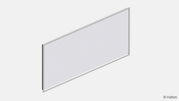
| Installation frame | IF | For installation without plenum | |
| Wax-bulb actuator | MT | The actuator controls the vane angle depending on the supply air temperature |
|
| Flow adjustment damper | OD | Aluminium opposite blade damper for airflow adjustment |
|
| Fastening | Visible screw fastening | SF | Screw fastening |
| Concealed screw fastening | CC | For installation with Halton BDR plenum or IF frame | |
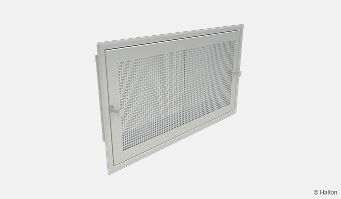
| Plenum BDR (subproduct) |
Model (M) |
S | Standard |
| L | L-shape | ||
| T | T-shape | ||
| Sizes | L | Length (mm) | |
| H | Height (mm) | ||
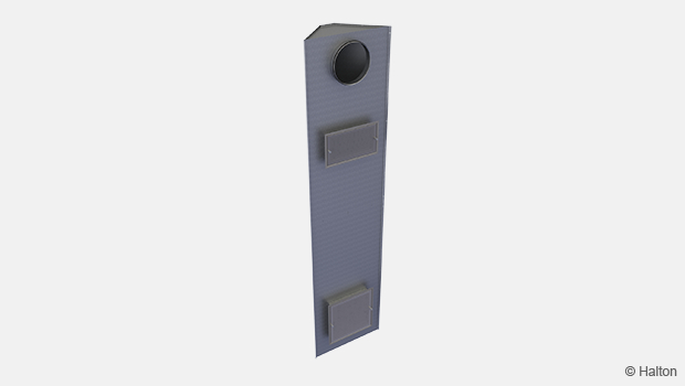
| Balancing plenum PRL (subproduct) | Model (M) |
A | Supply inlet (Left-Right connection) with sound attenuation option |
| B | Supply inlet (Back connection) with sound attenuation option | ||
| C | Supply inlet (Top/Bottom connection) with sound attenuation option | ||
| D | Exhaust outlet (Left-Right connection) with sound attenuation option | ||
| E | Exhaust outlet (Back connection) with sound attenuation option | ||
| F | Exhaust outlet (Top/Bottom connection) with sound attenuation option | ||
| G | No accessories (Left-Right connection) | ||
| H | No accessories (Back connection) | ||
| I | No accessories (Top/Bottom connection) | ||
| Sizes | W | Width of grille connection [mm] | |
| H | Height of grille connection [mm] | ||
| D | Connection size of duct [mm] |
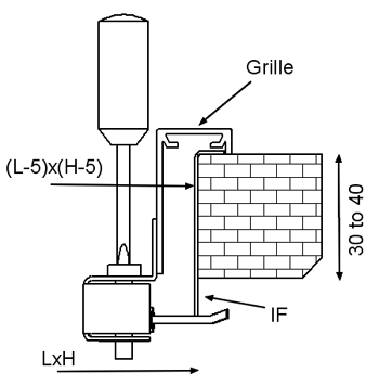
Wax-bulb actuator
In applications, where both heating and cooling are provided, the air pattern can be changed automatically via the wax-bulb actuator.
The wax-bulb actuator alters the angles of the horizontal rear vane depending on the supply air temperature. Neither auxiliary energy nor dedicated control system are needed.
When cold air is supplied at a temperature up to 18 °C the supply jet is horizontal. The vane angle is 0°. As the supply air temperature rises, the actuator piston progressively changes the angle of the rear vanes to direct the supply air jet downwards. Vane angle reaches 45° in 10 to 20 minutes.
No maintenance is required for the wax-bulb actuator.
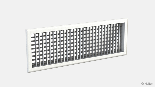
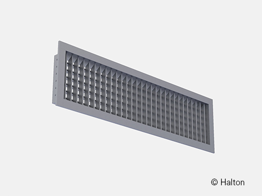
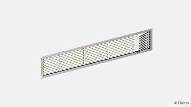
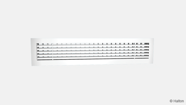
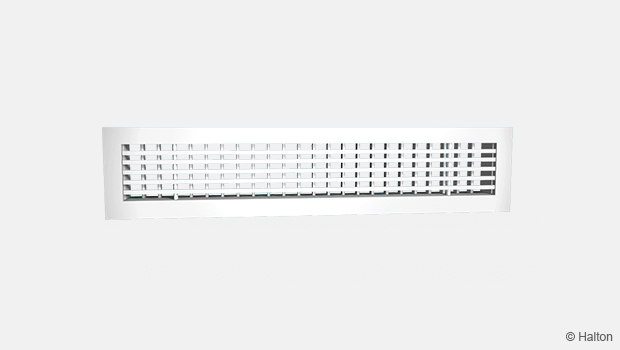
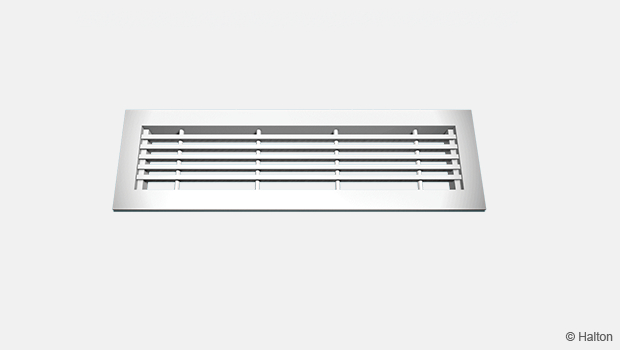
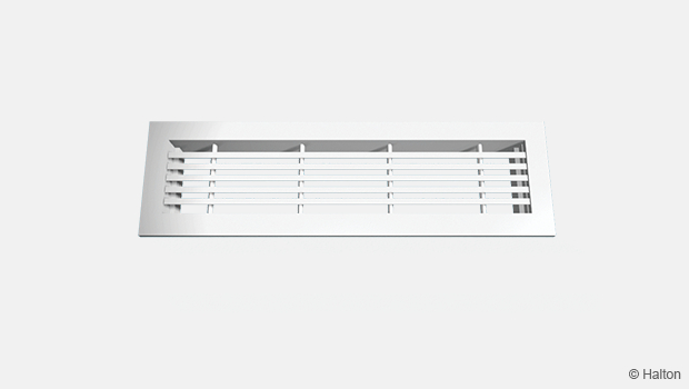
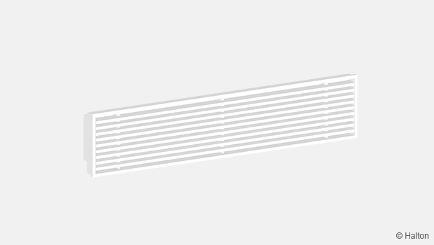
Product models
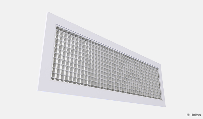
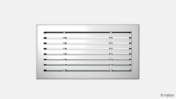
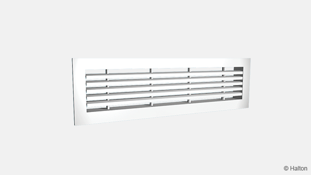
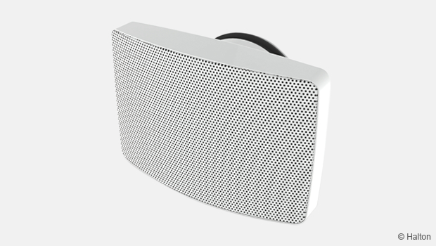
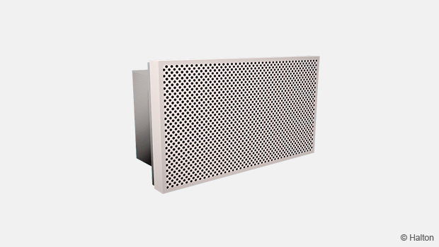
Halton WDD, rounded frame (R)
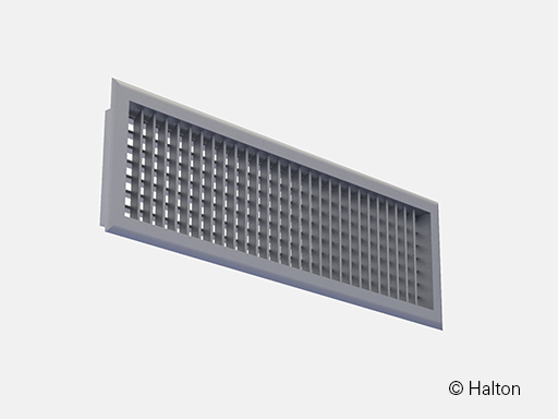
Halton WDD, flat frame (F, F2)
Operating principle
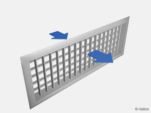
Supply air is supplied with horizontal and vertical deflection through the vanes into the space. The supply air mixes with the room air in front of the grille.
The supply air is directed with the horizontal adjustable vanes.
Moving the vertical vanes can change the length and form of the flow pattern.
In wall installations, the recommended distance from the ceiling is 200 mm, when the supply air is directed to the ceiling.The rear vane angle can also be controlled by optional wax-bulb actuator.
The Halton WDD grille can also be used for exhaust.
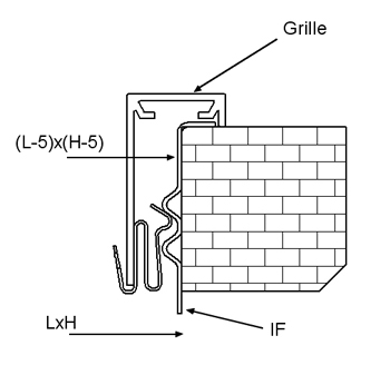
Installation
For ceiling installation, we recommend using visible screw fastening. The auto screws, 4.2×25 are supplied.
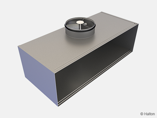
The grille is connected to the circular duct using either a Halton PRL balancing plenum or a Halton BDR plenum or alternatively directly to the rectangular duct using the IF/WDD installation frame.
Installation frame, IF/WDD Balancing plenum, PRL Plenum box, BDR
Fastening options
Clips, as standard (CL)
The grilles are delivered with clips fastening as standard.
Clips fastening is used with Halton PRL, Halton BDR and IF/WDD.
Concealed screw (CC)
Concealed screw fastening is possible when the grille is installed with an IF/WDD installation frame or with a Halton BDR plenum, not with a Halton PRL balancing plenum.
Pre-drilled screw holes are integrated into the Halton BDR for ease of installation.
For ceiling installation, concealed screw fastening is recommended.
The dimensions of the installation holes are LxH when an installation frame is used, and (L-5) x (H-5) without installation frame.
Visible screw (SF) – Frame 30×48 mm (F2)

Commissioning
Supply
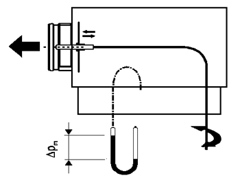
In order to enable airflow adjustment and measurement of airflow rate we recommend connecting the diffuser to a Halton BDR plenum or Halton PRL balancing plenum equipped with the MSM module. The supply flow rate is determined by using the measurement and adjustment module MSM.
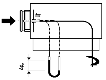
Detach the grille and pass the tubes and control spindle through the grille. Measure the differential pressure with a manometer. The flow rate is calculated using the formula below:
![]()
where
- qv Airflow rate [l/s] or [m3/h]
- ∆pm Measured pressure [Pa]
- k The k-factor given as a function of mounting and diameter (see the table below)
Adjust the airflow rate by rotating the control spindle until the desired setting is achieved.
Lock the damper position with a screw.
Replace the tubes and spindle into the plenum and replace the grille.
The k-factor for installations with different safety distances
(D= duct diameter)
| Duct connection (BDR) | k-factor of MSM adjuster, opening > 0 [l/s] | |
| >6D | min 3D | |
| 100 | 6 | 7 |
| 125 | 10 | 12 |
| 160 | 19 | 22 |
| 200 | 28 | 32 |
| 250 | 49 | 51 |
| 315 | 77 | 83 |
Exhaust
The airflow rate is selected by measuring the pressure difference between the measurement tap on the Halton PRL balancing plenum or Halton BDR plenum and theroom air.
The corresponding airflow rate is calculated and can be adjusted by turning the control spindle of the adjustment unit MEM.
Airflow adjustment damper OD
The airflow rate can also be adjusted by turning the damper blades behind the grille with a screwdriver. The measurement is carried out when grille is installed.
Maintenance
Remove the grille by gently drawing it out by the frame. Use a screwdriver if necessary. Clean the parts by wiping them with a damp cloth.
Push the grille back into place until the springs lock (or fix by screwing on the concealed screws).
Option with balancing plenum
Remove the measurement and adjustment module by gently pulling the shaft (NB notthe control spindle). Wipe the parts with a damp cloth, instead of immersing in water.
Remount the measurement and adjustment module by pushing in the shaft until the module meets the stopper.
Push the grille back into place so that the clips lock.
Specification
The grille is made of extruded aluminium, with an anodised or epoxy-painted with a white (RAL9003) standard colour.
The bevel angles of the outer frame are welded so that the joints are almost invisible.
The Halton WDD grille has horizontal and vertical adjustable vanes. The rear vanes direct the supply air jet horizontally. The length and form of the air pattern are adjusted by turning the front vanes.
The supply air jet shall be controlled according to supply air temperature by a waxbulb actuator.
The grille can be connected to the ductwork using a balancing plenum, which comprises sound attenuation material made of polyester fibre or mineral wool with a washable surface.
The plenum comprises an airflow measurement and adjustment unit.
The grille is removable in order to provide access to the measurement and adjustment module in the plenum.
Order code
WDD-L-H; FM-VP-FS-FI-CO-ZT-AC
L = Length [mm]
200, +1, .., 1500
H = Height (mm]
100, +1, .., 600
Other options and accessories
FM = Frame model
R Rounded
F Flat (22 mm)
F2 Flat (30 mm)
VP = Vane positioning
V Vertical at front
H Horizontal at front
FS = Fastening
CL Clips
SF Screw fastening
CC Concealed screw fastening
FI = Finishing
PN Painted
AN Anodised
MF Mill finished
CO = Colour
SW Signal white (RAL 9003)
X Special colour (RAL xxxx)
ZT = Tailored product
N No
Y Yes (ETO)
AC = Accessories
IF Installation frame
OD Opposed blade damper
WM Wax-bulb actuator
Sub products
BDR Plenum
PRL Plenum
Order code example
WDD-200-100; FM=R, VP=V, FS=CL, FI=AN, CO=N, ZT=N, AC=IF
Downloads
"*" indicates required fields
Halton AGC – Exhaust grille
product
Halton AHD – Exhaust grille
product
Halton ALE – Universal grille
product

Halton ALU – Universal grille
product
Halton ASC – Window bench grille
product
Halton AWE – Universal grille
product
Halton AWU – Universal grille
product
Halton BDR – Plenum for grilles
product
Halton BOS – Supply air valve
product
Halton EVA – Exhaust air unit
product
Halton FLE – Floor grille
product
Halton FLU – Floor grille
product
Halton GDD – Grille for circular duct installation
product
Halton GSP – Floor grille
product
Halton HDF – Exhaust grille with filter
product
Halton PRL – Plenum for grilles
product
Halton Vita VSC – Exhaust unit
product
Halton Vita VSG – Exhaust grille
product
Halton WDD – Universal grille
product