Product / BOX
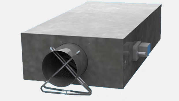
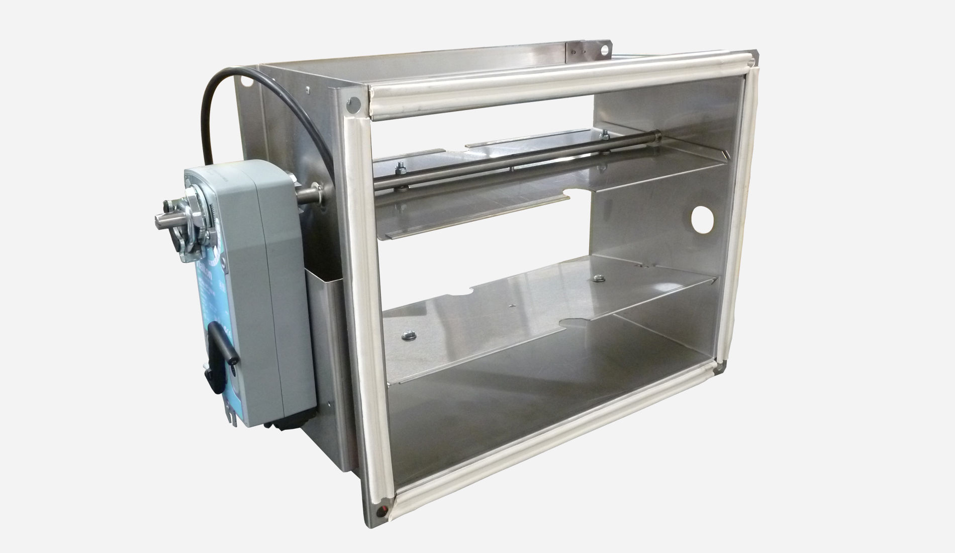
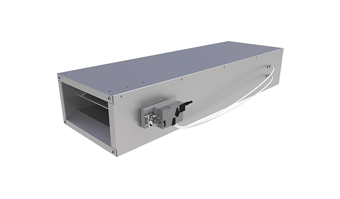
Halton BOX – Airflow management unit (VAV)
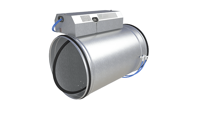
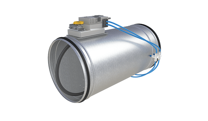
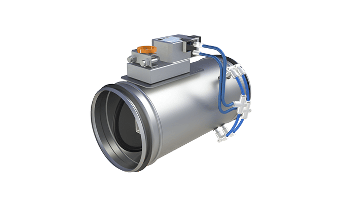
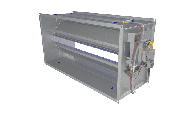
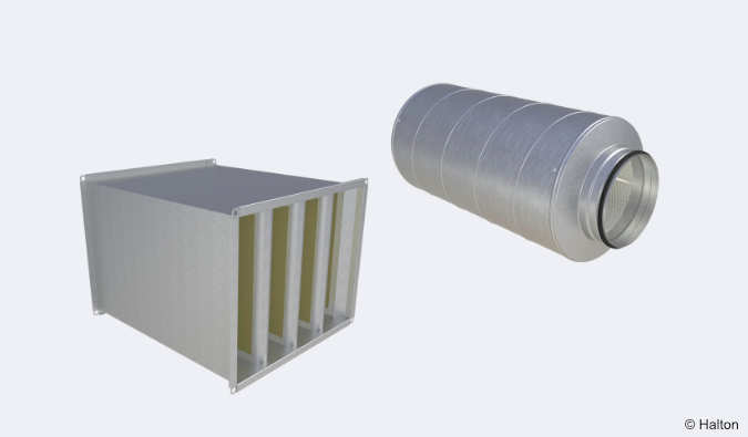
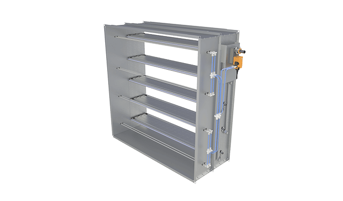
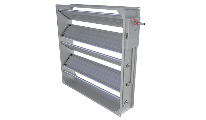
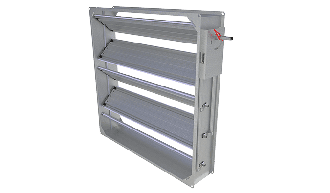
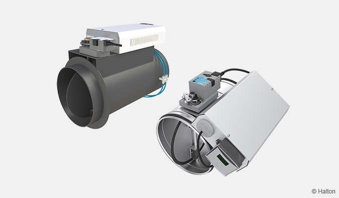
VAV and CAV damper units have a unique double blade construction with/without an integrated silencer for excellent sound level and for different airflow and duct pressure control applications. Factory-set airflow range limits (min./max. airflow rates).
- Variable or constant airflow rate operation
- Pressure-independent operation
Overview
- Airflow management and control unit
- Variable or constant airflow rate operation
- Pressure-independent operation
- Galvanised steel construction
- Airflow management plenum with acoustic attenuation (high density mineral wool)
- Factory set airflow range limit
Product models and accessories
- Electrical or hot water reheating unit
- Outlet plenum with one or more circular connections
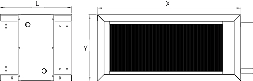
Dimensions
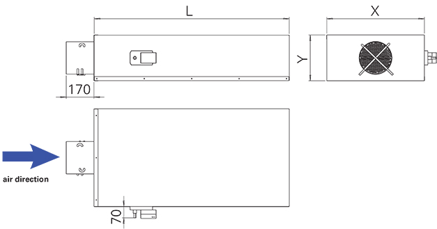
Halton BOX, supply
Halton BOX, exhaust
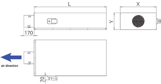
Actuator on right side of the damper as standard. Available on left side as tailored product. Ask your sales.
Long version: BOX/L-D
| Description | Diameter [mm] | Length [mm] | Height [mm] | Depth [mm] |
| D | X | Y | L | |
| 25 mm Insulation, I1 | 100 | 400 | 250 | 1000 |
| 125 | 400 | 250 | 1000 | |
| 160 | 400 | 250 | 1000 | |
| 200 | 600 | 280 | 1200 | |
| 250 | 700 | 320 | 1400 | |
| 315 | 800 | 400 | 1600* | |
| 355 | 1000 | 450 | 1600* | |
| 400 | 1000 | 450 | 1600* | |
| 500 | 1300 | 550 | 1800 | |
| 40 mm Insulation, I2 | 100 | 430 | 280 | 1000 |
| 125 | 430 | 280 | 1000 | |
| 160 | 430 | 280 | 1000 | |
| 200 | 630 | 310 | 1200 | |
| 250 | 730 | 350 | 1400 | |
| 315 | 830 | 430 | 1600 | |
| 355 | 1030 | 480 | 1600* | |
| 400 | 1030 | 480 | 1600* | |
| 500 | 1330 | 580 | 1800* |
* in 2 parts
Short version: BOX/S-D
| Description | Diameter [mm] | Length [mm] | Height [mm] | Depth [mm] |
| D | X | Y | L | |
| 25 mm Insulation, I1 | 100 | 400 | 250 | 600 |
| 125 | 400 | 250 | 600 | |
| 160 | 400 | 250 | 600 | |
| 200 | 600 | 280 | 600 | |
| 250 | 700 | 320 | 900 | |
| 315 | 800 | 400 | 900 | |
| 355 | 1000 | 450 | 900 | |
| 400 | 1000 | 450 | 900 | |
| 500 | 1300 | 550 | 1000 | |
| 40 mm Insulation, I2 | 100 | 430 | 280 | 600 |
| 125 | 430 | 280 | 600 | |
| 160 | 430 | 280 | 600 | |
| 200 | 630 | 310 | 600 | |
| 250 | 730 | 350 | 900 | |
| 315 | 830 | 430 | 900 | |
| 355 | 1030 | 480 | 900 | |
| 400 | 1030 | 480 | 900 | |
| 500 | 1330 | 580 | 1000 |
Material
| Part | Material |
| Plenum | Galvanised steel |
| Measurement probe | Aluminium |
| Acoustic insulation | High density mineral wool |
| Blade | Galvanised steel |
| Perforated sheet steel | Galvanised steel |
| External insulation | Mineral wool protected by galvanised steel frame |
Function
The Halton BOX variable airflow rate management unit contains a complete regulation loop. This includes an aluminium probe measurement system to take the average value measured over the whole crossing surface, an activator mounted on the blade axis and a controller.
The measurements made are sent to the controller which compares these values with the required setpoint value; depending on the measured difference, a signal is then sent to the actuator so that the unit compensates for this difference.
An analogue signal that enables the setpoint to be shifted may also be sent to the controller. The flow rate is regulated between the min and max rate values programmed into the controller.
The regulation loop is closed and operates independently of the variations in upstream pressure. The regulation may also be static pressure regulation (in the duct or in the premises).
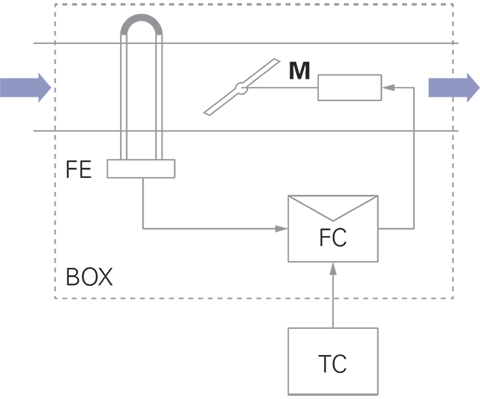
M Actuator
PE Dynamic pressure measurement probe
FC Airflow controller
TC Thermostat or room sensor
Product models
The Halton BOX airflow management unit is available in several versions.
The long version is used to reduce the air flow noise; the version with exterior sound proofing is used to reduce the noise emitted by the unit.
| Model | Application | Execution |
| BOX/S-S; IN=I1 | Supply | Short version. 25 mm insulation |
| BOX/L-S; IN=I1 | Supply Low noise level to be complied |
Long version. Integrated sound attenuator 25 mm insulation |
| BOX/S-E; IN=I1 | Exhaust | Short version. 25 mm insulation |
| BOX/L-E; IN=I1 | Exhaust Low noise level to be complied |
Long version. 25 mm insulation |
| BOX/S-S; IN=I2 | Supply | Short version. 40 mm insulation |
| BOX/L-S; IN=I2 | Supply Low noise level to be complied |
Long version. Integrated sound attenuator 40 mm insulation |
| BOX/S-E; IN=I2 | Exhaust | Short version. 40 mm insulation. |
| BOX/L-E; IN=I2 | Exhaust Low noise level to be complied |
Long version. 40 mm insulation. |
Accessories
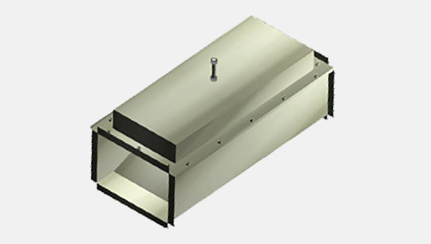
Water reheating unit WBO
- Rectangular water reheating to be mounted downstream of the airflow management unit Halton BOX
- Lateral water connection
- Fixing on the Halton BOX by toggle latches
- Cooling coil with condensate tray can be manufactured upon request.
WBO Dimensions
| Description | D | X | Y | L |
| 25 mm Insulation, I1 | 100 | 400 | 250 | 300 |
| 125 | 400 | 250 | 300 | |
| 160 | 400 | 250 | 300 | |
| 200 | 600 | 280 | 300 | |
| 250 | 700 | 320 | 300 | |
| 315 | 800 | 400 | 500 | |
| 355 | 1000 | 450 | 600 | |
| 400 | 1000 | 450 | 600 | |
| 500 | 1300 | 550 | 600 | |
| 40 mm Insulation, I2 | 100 | 430 | 280 | 300 |
| 125 | 430 | 280 | 300 | |
| 160 | 430 | 280 | 300 | |
| 200 | 630 | 310 | 300 | |
| 250 | 730 | 350 | 300 | |
| 315 | 830 | 430 | 500 | |
| 355 | 1030 | 480 | 600 | |
| 400 | 1030 | 480 | 600 | |
| 500 | 1330 | 580 | 600 |
Water reheating power
| Size | Airflow [m3/h] |
Airflow [l/s] |
Power | ΔP [Pa] |
| 100 | 58 | 16 | 425 | 2 |
| 97 | 27 | 641 | 3 | |
| 136 | 38 | 824 | 5 | |
| 175 | 49 | 986 | 7 | |
| 214 | 59 | 1129 | 10 | |
| 251 | 70 | 1255 | 13 | |
| 125 | 90 | 25 | 603 | 3 |
| 155 | 43 | 904 | 6 | |
| 220 | 61 | 1149 | 10 | |
| 285 | 79 | 1363 | 15 | |
| 350 | 97 | 1555 | 21 | |
| 414 | 115 | 1727 | 28 | |
| 160 | 144 | 40 | 859 | 6 |
| 254 | 71 | 1266 | 13 | |
| 364 | 101 | 1593 | 23 | |
| 474 | 132 | 1877 | 35 | |
| 584 | 162 | 2115 | 49 | |
| 695 | 193 | 2326 | 65 | |
| 200 | 227 | 63 | 1440 | 4 |
| 427 | 119 | 2238 | 10 | |
| 627 | 174 | 2882 | 18 | |
| 827 | 230 | 3424 | 28 | |
| 1027 | 285 | 3889 | 40 | |
| 1226 | 341 | 4315 | 54 | |
| 250 | 360 | 100 | 2320 | 4 |
| 675 | 188 | 3611 | 11 | |
| 990 | 275 | 4644 | 19 | |
| 1305 | 363 | 5512 | 30 | |
| 1620 | 450 | 6288 | 43 | |
| 1936 | 538 | 6953 | 58 | |
| 315 | 569 | 158 | 3530 | 5 |
| 1039 | 289 | 5378 | 12 | |
| 1509 | 419 | 6849 | 22 | |
| 1979 | 550 | 8086 | 34 | |
| 2449 | 680 | 9145 | 49 | |
| 2920 | 811 | 10120 | 65 | |
| 355 | 736 | 204 | 4577 | 4 |
| 1395 | 388 | 7205 | 10 | |
| 2054 | 571 | 9286 | 19 | |
| 2713 | 754 | 11036 | 29 | |
| 3372 | 937 | 12535 | 42 | |
| 4032 | 1120 | 13856 | 56 | |
| 400 | 900 | 250 | 5330 | 5 |
| 1600 | 444 | 7899 | 13 | |
| 2300 | 639 | 9964 | 22 | |
| 3000 | 833 | 11702 | 34 | |
| 3700 | 1028 | 13188 | 49 | |
| 4400 | 1222 | 14557 | 65 | |
| 500 | 1404 | 390 | 8749 | 5 |
| 2643 | 734 | 13611 | 12 | |
| 3882 | 1078 | 17480 | 22 | |
| 5121 | 1423 | 20724 | 34 | |
| 6360 | 1767 | 23493 | 48 | |
| 7600 | 2111 | 25923 | 65 |
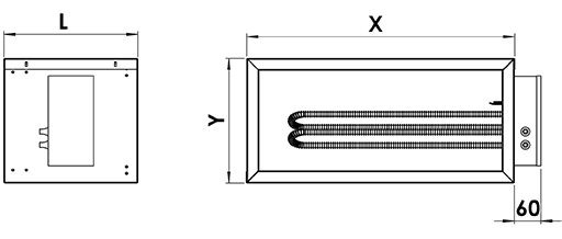
Electrical reheating unit WBF
- Electrical reheating with electrical supply 230 V single phase (1 or 2 resistances), 230/400 V three phase (3 resistances)
- Safety thermostat with manual reset
- Minimum air velocity: 2 m/s.
WBF Dimensions
| Description | D | X | Y | L |
| 25 mm Insulation, I1 | 100 | 400 | 250 | 300 |
| 125 | 400 | 250 | 300 | |
| 160 | 400 | 250 | 300 | |
| 200 | 600 | 280 | 300 | |
| 250 | 700 | 320 | 300 | |
| 315 | 800 | 400 | 500 | |
| 355 | 1000 | 450 | 600 | |
| 400 | 1000 | 450 | 600 | |
| 500 | 1300 | 550 | 600 | |
| 40 mm Insulation, I2 | 100 | 430 | 280 | 300 |
| 125 | 430 | 280 | 300 | |
| 160 | 430 | 280 | 300 | |
| 200 | 630 | 310 | 300 | |
| 250 | 730 | 350 | 300 | |
| 315 | 830 | 430 | 500 | |
| 355 | 1030 | 480 | 600 | |
| 400 | 1030 | 480 | 600 | |
| 500 | 1330 | 580 | 600 |
Plenum PBO
Plenum with 1 circular outlet to be mounted downstream of the airflow management unit Halton BOX.
PBO dimensions
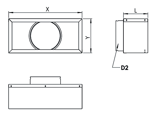
| Description | D | X | Y | D2 | L |
| 25 mm insulation, I1 | 100 | 400 | 250 | 125 | 200 |
| 125 | 400 | 250 | 160 | 200 | |
| 160 | 400 | 250 | 200 | 200 | |
| 200 | 600 | 280 | 250 | 200 | |
| 315 | 800 | 400 | 355 | 200 | |
| 355 | 1000 | 450 | 400 | 200 | |
| 40 mm insulation, I2 | 100 | 430 | 280 | 125 | 200 |
| 125 | 430 | 280 | 160 | 200 | |
| 160 | 430 | 280 | 200 | 200 | |
| 200 | 630 | 310 | 250 | 200 | |
| 315 | 830 | 430 | 355 | 200 | |
| 355 | 1030 | 480 | 400 | 200 |
Upon request, outlet plenum PBO:
- with side connection
- with several connections.
Control
Control units (CU)
The Halton BOX airflow control damper can be equipped with several different control units for either airflow or duct pressure control.
Airflow control
- For supply and exhaust installations
- Complete damper shutt off
- Operating ambient temperature range from 0 to 50°C
- Ambient relative humidity < 95%, non condensing
- Analog command signal: 0-10 V or 2-10 V.
Available airflow controllers:
EE NMV-D3-MP (MP bus), 10 Nm
EC LMV-D3-MP (MP bus), 5 Nm
EK NMV-D3-MF.1 HI (DC 0/2…10 V), 10 Nm
EM LMV-D3-MF.1 HI (DC 0/2…10 V), 5 Nm
ER LMV-D3-KNX (KNX bus), 5 Nm
ES NMV-D3-KNX (KNX bus), 10 Nm
ET LMV-D3-MOD (Modbus RTU), 5 Nm
EU NMV-D3-MOD (Modbus RTU), 10 Nm
EH GDB181.1E/3 (DC 0/2…10 V), 5 Nm
EG GLB181.1E/3 (DC 0/2…10V), 10 Nm
EV GDB181.1E/KN (KNX bus), 5 Nm
EW GLB181.1E/KN (KNX bus), 10 Nm
EB GDB181.1E/MO (Modbus RTU), 5 Nm
EF GLB181.1E/MO (Modbus RTU), 10 Nm
V1 LM24A-VST. (DC 0/2…10 V), 5 Nm+VRU-D3-BAC
V2 NM24A-VST. (DC 0/2…10 V), 10Nm+VRU-D3-BAC
V3 LMQ24A-VST. 2.5 sec (DC 0/2…10 V), 4 Nm+VRU-D3-BAC
V4 NMQ24A-VST. 4 sec (DC 0/2…10 V), 8 Nm+VRU-D3-BAC
HM ECL-VAV-S. HAV (LonWorks), 5Nm
HK ECL-VAV-N. HAV + NM24A-SR (LonWorks), 10 Nm
The EE, EC, EM and EK airflow controllers feature a differential pressure sensor crossed by a low rate. Therefore these airflow controllers must not be used in a highly contaminated environment. The EG airflow controller pressure sensor is a model with membrane and is therefore sealed and no flow can cross it.
The table below provides the nominal airflow control ranges for standard controls (nominal pressure: 150 Pa):
| Size | Nominal rate | Minimal rate (standard) | Minimal rate (special) | |||
| m3/h | l/s | m3/h | l/s | m3/h | l/s | |
| 100 | 287 | 80 | 58 | 16 | 28 | 8 |
| 125 | 469 | 130 | 90 | 25 | 46 | 13 |
| 160 | 808 | 224 | 144 | 40 | 84 | 23 |
| 200 | 1210 | 336 | 227 | 63 | 136 | 38 |
| 250 | 1940 | 539 | 360 | 100 | 214 | 59 |
| 315 | 3145 | 874 | 569 | 158 | 353 | 98 |
| 355 | 4031 | 1120 | 736 | 204 | 444 | 123 |
| 400 | 5159 | 1433 | 900 | 250 | 617 | 171 |
| 500 | 8160 | 2267 | 1404 | 390 | 971 | 270 |
Nominal rate: Maximal admissible airflow for the Halton BOX
Minimal airflow std: Minimal airflow, value for standard controls
Minimal airflow special: Minimal airflow, value for control with static or quasi-static pressure sensor
Pressure regulation
- Used for supply and exhaust
- Static pressure range depends on the probe (for example, EG control: adjustement from 0 to 300 Pa)
- Operating ambient temperature range from 0 to 50°C
- Ambient relative humidity < 95%, non condensing
Available airflow controllers:
EG GLB181.1E/3 (DC 0/2…10V), 10 Nm
Installation
Safety distance
The Halton BOX airflow control damper is installed taking into account the required safety distances
(see figure). These distances are valid for supply and exhaust. If the safety distances below are not respected, the dynamic pressure measurement can be false.
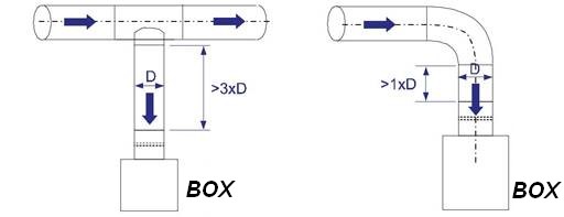
For the supply, in static pressure control, the minimum safety distance for the static measurement unit after the control damper is 5 x D in supply air applications. However, the pressure sensor position is typically halfway along or in the last third of in the last third of the duct branch length.
Commissioning
The actual airflow rate can be calculated as a function of differential pressure at the measurement probe and the measurement probe k factor. The proper k factor can be found in the documentation supplied with the product.
qv Actual airflow rate [l/s]
k k factor of the product
∆P_m Differential pressure of the measurement probe [Pa]
| NS | k [l/s] | k [m3/h] |
| 100 | 6,5 | 23,5 |
| 125 | 10,6 | 38,2 |
| 160 | 18,3 | 65,8 |
| 200 | 27,4 | 98,8 |
| 250 | 44 | 158,4 |
| 315 | 71,4 | 256,9 |
| 400 | 117 | 421,2 |
| 500 | 185,1 | 666,4 |
The EE, EC, EK and EM airflow controllers are equipped with a dynamic pressure differential sensor which is subjected to a low airflow. Therefore, a manual manometer cannot be connected in parallel with the airflow controller for differential pressure measurement. If a manual manometer is used, the airflow controller power supply shall be switched off in order to stop damper movement during measurement of the airflow probe differential pressure. Note that the duct pressure might vary during the measurement.
The EG airflow controller is equipped with a static membrane pressure sensor including an automatic zero point calibration, and there is no airflow through the differential pressure sensor of the controller. Therefore,
a manual differential measurement manometer can be connected in parallel to the airflow controller
(for example, with tube T-branches), and both measurements can operate in parallel with continuous control.
Specification
The Halton BOX airflow management unit is used for airflow adjustment in variable air volume installations, in supply as well as exhaust.
It is composed of:
- a circular inlet spigot equipped with an aluminium airflow measurement probe,
- a damper blade
- a rectangular part equipped with a sound attenuator, allowing air expansion.
The airflow measurement probe measures the average differential pressure across the whole surface of the inlet spigot, thus it allows the correct measurement of the airflow crossing the unit.
The damper actuator is made of two blades with a kinematic link, it enables the reduction of airborne noise as soon as the air enters the unit.
When closed, the damper is air tight.
The main blade is equipped with a gasket to reduce the friction and thus the needed torque of the actuator. The electric power consumption of the regulation loop is also reduced.
The Halton BOX casing airtightness is optimised by a construction with with limited cuttings. The acoustic part of the unit shall be equipped with an asymmetric sound attenuator, enabling an additionnal acoustic attenuation, particularly in the low frequency-range.
The Halton BOX selection is carried out according to its airflow range.
The minimum and maximum airflow values are indicative and can differ by control type or brand.
The Halton BOX is delivered factory-set according to the customer demand.
Factory parameters values as well as identification of the unit in the installation are marked on each unit.
This inside facing consitutes a smooth and washable surface thus limits the microbial development. Thus the unit can be used in areas such as hospitals, laboratories, electronic industries,…
The unit is made of galvanised steel and measurement probes of aluminium.
The unit sound attenuation is made of Euroclass A2 s1 d0 high density mineral wool with coating to avoid tearing, even at high velocities. The insulating material is also inert to bacterial development and can be used in demanding spaces such as hospitals, laboratories, electronic environment.
The unit can be equipped with a 40 mm thick insulation to reduce radiated noise emission.
For supply application, the unit can be equipped with a hot water reheater or an electric reheater.
Order code
BOX-V-M-D; CU-SE-TF-IN-ZT
| Main options | |
| V = Version | |
| L | Long |
| S | Short |
| M = Model | |
| S | Supply |
| E | Exhaust |
| D = Duct connection size [mm] | 100, 125, 160, 200, 250, 315, 355, 400, 500 |
| Other options and accessories | |
| CU = Control units | |
| EM | LMV-D3-MF-F.1 HI (DC 0/2…10 V), 5 Nm |
| EK | NMV-D3-MF-F.1 HI (DC 0/2…10 V), 10 Nm |
| EC | LMV-D3-MP (MP bus), 5 Nm |
| EE | NMV-D3-MP (MP bus), 10 Nm |
| ER | LMV-D3-KNX (KNX bus), 5 Nm |
| ES | NMV-D3-KNX (KNX bus), 10 Nm |
| ET | LMV-D3-MOD (Modbus RTU), 5 Nm |
| EU | NMV-D3-MOD (Modbus RTU), 10 Nm |
| EH | GDB181.1E/3 (DC 0/2…10 V), 5 Nm |
| EG | GLB181.1E/3 (DC 0/2…10V), 10 Nm |
| EV | GDB181.1E/KN (KNX bus), 5 Nm |
| EW | GLB181.1E/KN (KNX bus), 10 Nm |
| EB | GDB181.1E/MO (Modbus RTU), 5 Nm |
| EF | GLB181.1E/MO (Modbus RTU), 10 Nm |
| V1 | LM24A-VST. (DC 0/2…10 V), 5 Nm+VRU-D3-BAC |
| V2 | NM24A-VST. (DC 0/2…10 V), 10Nm+VRU-D3-BAC |
| V3 | LMQ24A-VST. 2.5 sec (DC 0/2…10 V), 4 Nm+VRU-D3-BAC |
| V4 | NMQ24A-VST. 4 sec (DC 0/2…10 V), 8 Nm+VRU-D3-BAC |
| HM | ECL-VAV-S, HAV (LonWorks), 5Nm |
| HK | ECL-VAV-N, HAV + NM24A-SR (LonWorks), 10 Nm |
| SE = Sensors | |
| NA | Not assigned |
| DS1 | Duct sensor (CO2G, Duct CO2) |
| P1 | Differential pressure transmitter (HDP-PE) |
| TF = Transformer | |
| NA | Not assigned |
| TF1 | 230/24 transformer (35VA) |
| IN = Insulation | |
| I1 | 25 mm (standard) |
| I2 | 40 mm |
| ZT = Tailored product | |
| N | No |
| Y | Yes (ETO) |
Order code example
BOX-L-S-200; CU=EM, SE=DS1, TF=NA, IN=I1, ZT=N
Downloads
"*" indicates required fields
ABD – Automated Balancing Damper for kitchen ventilation (CE)
product
ABD – Automatic balancing damper for kitchen ventilation (ETL)
product
CID-01 – Zero leakage isolation damper
product
Halton BOX – Airflow management unit (VAV)
product
Halton Max MDC – Zone control damper for Halton Workplace system
product
Halton Max MLC – Airflow management damper (VAV)
product
Halton Max MOC – Airflow management damper (VAV)
product
Halton Max MOS – Airflow management damper (VAV)
product
Halton Max MSB – Slim airflow management damper (VAV)
product
Halton Max MUC – Ultrasound airflow management damper (VAV)
product

Halton PRA – Airflow management damper (CAV)
product
Halton PTS – Airflow management damper (single-blade)
product
Halton RMC – Airflow management damper (CAV)
product
Halton SA – Sound attenuator
product
Halton UKV – Airflow management damper (VAV)
product
Halton UTK – Multi-blade airflow management damper (CAV)
product
Halton UTT – Multi-blade airflow management damper (CAV)
product

Halton Vita VLR – Room airflow controller for Halton Vita Lab solutions
product
Halton Vita VLS – Fume cupboard controller for Halton Vita Lab solutions
product
KBD – Exhaust hood balancing damper (ETL)
product