Product / MOS
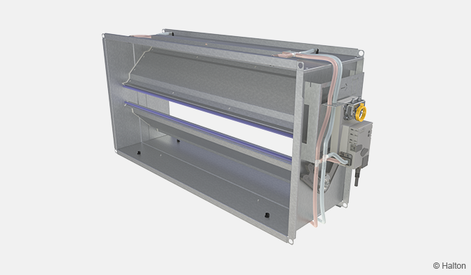
NEW! Halton Max MOS – Airflow management damper (VAV)
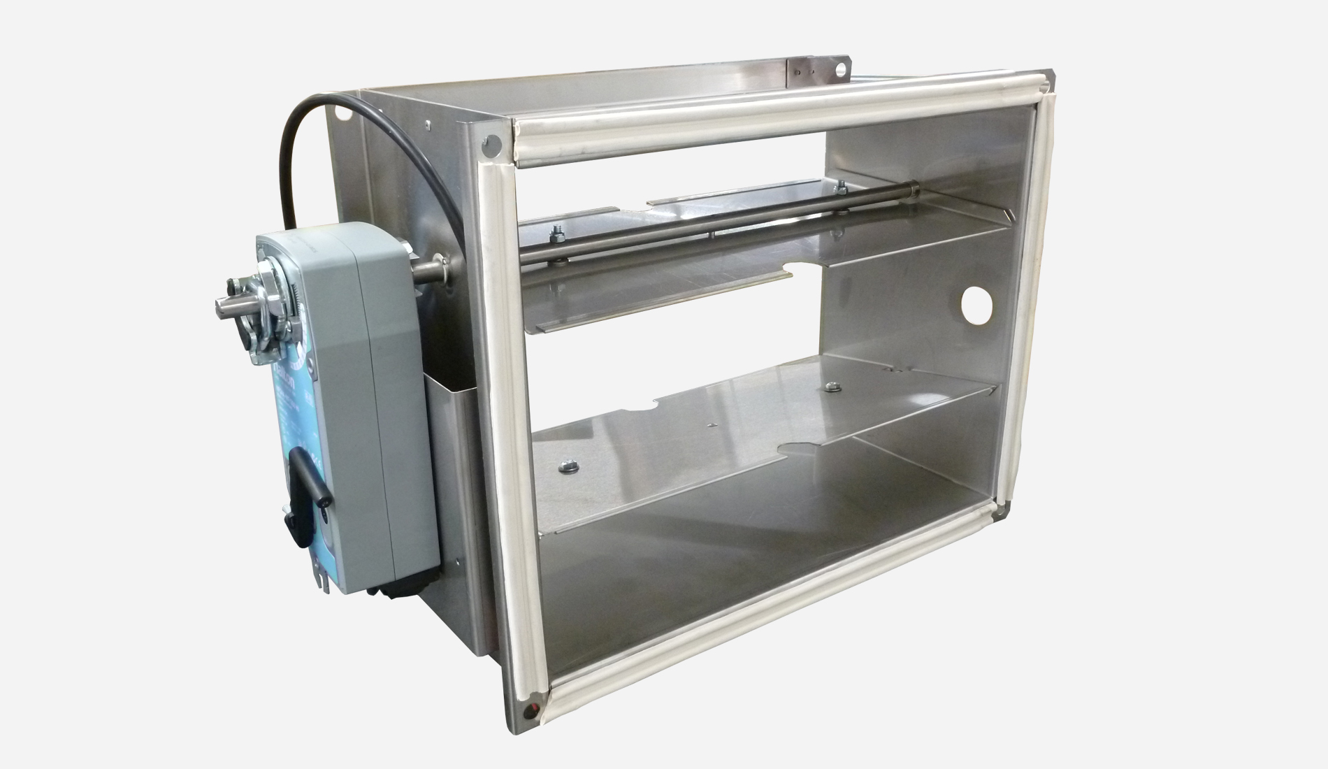
Halton Max MOS is a rectangular airflow management damper that needs no safety distances.
This airflow management damper is also designed to function at very low air velocity.
It uses advanced and patented airflow measurement based on the combination of the blade opening and the pressure difference between the blades.
- Variable (VAV) and constant (CAV) airflow control applications
- Supply and exhaust installations
Link to Revit object (MagiCAD Cloud)

Overview
Halton Max MOS is a rectangular airflow management damper that needs no safety distances. This airflow management damper is also designed to function at very low air velocity.
It uses advanced and patented airflow measurement based on the combination of the blade opening and the pressure difference between the blades.
Application areas
- Variable (VAV) and constant (CAV) airflow control applications
- Supply and exhaust installations
Key features
- 0.5-8 m/s airflow velocity
- Maximum differential pressure: 500 Pa over the damper
- Can be connected to Building Management System (BMS)
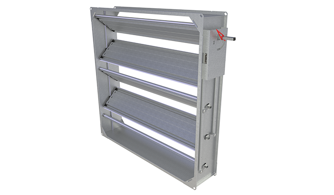
Operating principle
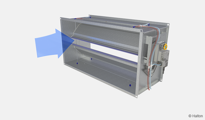
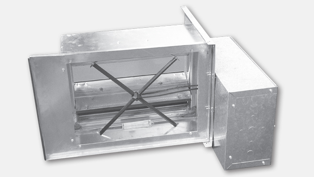
Fig. 1. Halton Max MOS measuring pressure difference between blades.
Thanks to short (<330mm) and smooth damper casing and uniquely positioned walled measurement probes therein, the flow measurement is based on amplified pressure difference of the damper which enables accurate (±10%) and undisturbed flow control even at low flow velocity (≥0,5m/s).
It also enables challenging flow conditions without the need for in-duct structures, which would cause unnecessary initial pressure losses and challenges for damper cleaning or additional duct sections for safety distance (0-distance). These would cause high additional costs and challenge for damper positioning and installation in other dampers. Also, eventual cleaning of the measurement probes may be done with pressurized air outside of the unit without the need to access measurement tubes or damper blades inside the damper.
Depending on the selected airflow controller, it can receive the airflow control signal via
- Modbus RTU network variable
- BACnet MSTP network variable
- An analog standard signal
The airflow setpoint can be modified between the minimum and maximum settings from the room controller interface or a BMS. The VAV controller can also send the actual value data back to the room interface controller. The communication protocol used for the signal between the room control interface and the VAV controller depends on the actuator model.
Key technical data
| Features | Description |
| Duct connection sizes | 200×150 mm up to 800×400 mm |
| Material | Galvanised steel or stainless steel (EN 1.4404/AISI 316L) |
| Air velocity range | 0.5 – 8 m/s |
| Operating range (ambient temperature) | 0-50℃ |
| Ambient relative humidity (non-condensing) | < 95% |
| Communication interface | Modbus RTU, BACnet MST, analog |
| Accessories |
|
| Standards and certifications |
|
| Maintenance | According to the building maintenance program |
Features and options
| Category | Feature (order code) |
Option (order code) |
Description |
| Size | Width of duct connection size W |
200, 250, 300, 400, 500, 600, 800 | Seven nominal width sizes. Units are in millimetres. |
| Height of duct connection size H |
150, 200, 250, 300, 400 | Five nominal height sizes. Units are in millimetres. | |
| Options | System package SP |
N | No |
| Material MA |
GS | Galvanised steel | |
| AS | Stainless steel (EN 1.4404/AISI 316L) | ||
| Insulation IN |
NA | No insulation material on the damper body | |
| I3 | Damper body is insulated with 50 mm mineral wool | ||
| Control unit CU |
EX | Control unit with analog signal (0…10V or 2…10V) | |
| EY | Control unit with Modbus RTU or BACnet MSTP | ||
| Sound attenuator, SA (subproduct*) |
Sound attenuator material AT |
W | Mineral wool |
| P | Polyester fibre | ||
| Reheater, RH (subproduct*) |
Model type RT |
E | Electrical heater |
| W | Water coil for heating or cooling | ||
| Control type, electrical RE |
NA | Not assigned | |
| 1 | Own room panel to adjust setpoint and measure temperature | ||
| 2 | On/off controller, need external controller to switch heater on or off | ||
| 3 | External 0-10V control signal to adjust heating element power | ||
| 4 | External PWM control signal to adjust heating element power | ||
| Control type, water RW |
NA | Not assigned | |
| H | Coil for heating | ||
| C | Coil for heating or cooling. Drip tray included. |
* Ordered separatly
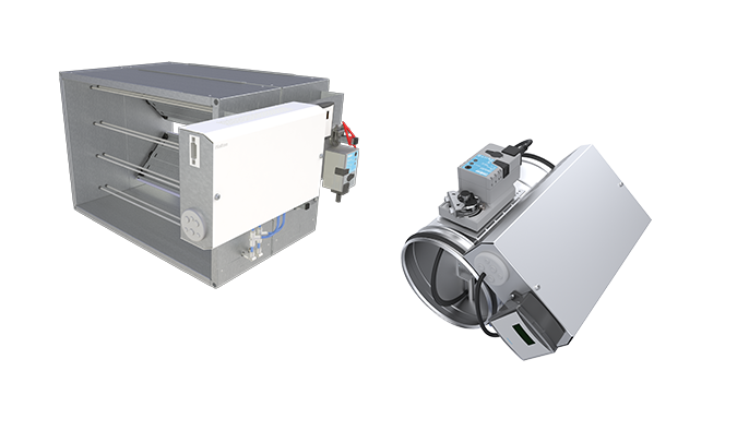
Control units
A range of control units are available for various application needs.
The control unit includes an integrated dynamic differential pressure sensor. The pressure sensor has a low bypass airflow rate through the sensor element. Depending on the model, airflow rate limits are adjusted on site with a mobile application or a dial for manual adjustment.
| Code | Actuator | Torque | Damper size | Communication interface | Order code |
| EX | Belimo | 10 Nm | 200 x 150 – 800 x 400 |
Analog 0..10V/2..10V |
EX = NMVD3W- MP.1 (DC 0/2…10 V), 10 Nm |
| EY | Belimo | 10 Nm | 200 x 150 – 800 x 400 |
Bus Modbus RTU BACnet MSTP |
EY = NMVD3W- MOD.1 (Modbus RTU/ BACnet MSTP), 10 Nm |
Quick selection
The operable airflow range for the Halton Max MOS corresponds to the duct air velocities of 0.5-8 m/s.
| Operating range [l/s) | ||||||||
| Width [mm] | 200 | 250 | 300 | 400 | 500 | 600 | 800 | |
| Height [mm] |
150 | 15-240 | 19-300 | 23-360 | 30-480 | 28-600 | 45-720 | – |
| 200 | 20-320 | 25-400 | 30-480 | 40-640 | 50-800 | 60-960 | 80-1280 | |
| 250 | – | 31-500 | 38-600 | 50-800 | 63-1000 | 75-1200 | 100-1600 | |
| 300 | – | – | 45-720 | 60-960 | 75-1200 | 90-1440 | 120-1920 | |
| 400 | – | – | – | 80-1280 | 100-1600 | 120-1920 | 160-2560 | |
Table 1. Operating range, min – max [l/s]
| Operating range [m3/h) | ||||||||
| Width [mm] | 200 | 250 | 300 | 400 | 500 | 600 | 800 | |
| Height [mm] |
150 | 54-864 | 68-1080 | 81-1296 | 108-1728 | 135-2160 | 162-2592 | – |
| 200 | 72-1152 | 90-1440 | 108-1728 | 144-2304 | 180-2880 | 216-3456 | 288-4608 | |
| 250 | – | 113-1800 | 135-2160 | 180-2880 | 225-3600 | 270-4320 | 360-5760 | |
| 300 | – | – | 162-2592 | 216-3456 | 270-4320 | 324-5184 | 432-6912 | |
| 400 | – | – | – | 288-4608 | 360-5760 | 432-6912 | 576-9216 | |
Table 2. Operating range, min – max [m3/h]
Stucture and materials
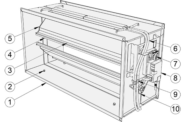
| No. | Part | Description | Note |
| 1 | Casing | Galvanised steel | Stainless steel (EN 1.4404/AISI 316L) also available. |
| 2 | Measurement probe | Polyurethane | – |
| 3 | Blade | Galvanised steel | Sandwich design. Stainless steel (EN 1.4404/AISI 316L) also available. |
| 4 | Blade gasket | Silicone | Heat-proof model: LTE silicone |
| 5 | Blades end gasket | Silicone | – |
| 6 | Measurement tube | Silicone | – |
| 7 | Rectangular drive shaft | Stainless steel (AISI 316L) | 12×12 mm |
| 8 | Control unit | Plastic, steel | PVC cable |
| 9 | Tube connector | Plastic | POM |
| 10 | Gear sector | Plastic | – |
Dimensions and weight

Fig. 3. Dimensions of Halton Max MOS

Fig. 4. Dimensions of Halton Max MOS, insulated model
| WxH [mm] |
L [mm] |
Weight [kg] |
| 200×150 | 250 | 3.5 |
| 200×200 | 250 | 3.8 |
| 250×150 | 250 | 4.5 |
| 250×200 | 250 | 4.1 |
| 250×250 | 330 | 4.0 |
| 300×150 | 250 | 4.2 |
| 300×200 | 250 | 4.6 |
| 300×250 | 330 | 5.5 |
| 300×300 | 250 | 5.6 |
| 400×150 | 250 | 4.8 |
| 400×200 | 250 | 5.3 |
| 400×250 | 330 | 6.4 |
| 400×300 | 250 | 6.6 |
| 400×400 | 250 | 7.6 |
| 500×150 | 250 | 5.5 |
| 500×200 | 250 | 6.0 |
| 500×250 | 330 | 7.2 |
| 500×300 | 250 | 7.5 |
| 500×400 | 250 | 8.6 |
| 600×150 | 250 | 6.0 |
| 600×200 | 250 | 6.6 |
| 600×250 | 330 | 8.0 |
| 600×300 | 250 | 8.1 |
| 600×400 | 250 | 9.3 |
| 800×200 | 250 | 8.3 |
| 800×250 | 330 | 9.9 |
| 800×300 | 250 | 10.3 |
| 800×400 | 250 | 11.8 |
Specification
Rectangular pressure-independent variable multiblade airflow control damper for supply and exhaust installations, fulfilling the following requirements:
Construction
- Short (<330mm) and smooth damper casing and uniquely positioned walled measurement probes therein.
- The flow measurement is based on amplified pressure difference of the damper. Accurate (±10%) and undisturbed flow control even at low flow velocity (≥0,5m/s) and challenging flow conditions. Control range at least 1:15
- Closed damper blade air leakage according to EN 1751 class 3.
- Casing air leakage according to EN 1751 class C.
- No internal structures that would cause unnecessary initial pressure losses and challenges for damper cleaning. Eventual cleaning of the measurement probes to be done with pressurized air outside of the unit without the need to access measurement tubes/vanes or damper blades inside the damper.
- No need to install additional duct sections for safety distance (zero safety distance).
Material
- Galvanised or stainless steel (EN 1.4404, AISI 316L)
Electrical data
- Modbus RTU, BACnet MSTP, or analogue connection
- Control signal range of analogue control mode is for input 0…10 VDC or 2 …10 VDC
- Feedback signal range of analogue control mode for output follows the selected control signal range 0…10 VDC
- Power supply voltage 24 V DC/AC
Parameter settings
- Designed airflow range can be set at the factory.
- Controller settings are adjustable on site with bus communication or external service tool.
Accessories
- Sound attenuator for noise reduction. Model with access panel available for easy maintenance.
- Electric reheat coil with an internal heating controller.
- Water coil for heating and cooling
Order code
| Main options | |
| W = Width of duct connection [mm] | 200, 250, 300, 400, 500, 600, 800 |
| H = Height of duct connection [mm] | 150, 200, 250, 300, 400 |
| Other options and accessories | |
| SP = System package | |
| N | No |
| MA = Material | |
| GS | Galvanised steel |
| AS | Stainless steel (EN 1.4404/AISI 316L) |
| IN = Insulation | |
| NA | Not assigned |
| I3 | Insulated, 50 mm |
| CU = Control unit | |
| EX | NMV-D3W-MP.1 (DC 0/2…10V), 10 Nm |
| EY | NMV-D3W-MOD.1 (Modbus RTU/BACnet MSTP), 10 Nm |
| ZT = Tailored product | |
| N | No |
| Y | Yes (ETO) |
| Sub products and accessories (ordered separately) | |
| SA | Sound attenuator |
| RH | Reheat coil |
Order code example
MOS-400-200; SP=N, MA=GS, IN=NA, CU=EX, ZT=NA
Installation
The Halton Max MOS airflow control damper can be installed to T-branch and curve, without safety distances. The accuracy of the measured airflow is given in a table below. Install the unit into the ductwork in such a way that the airflow direction through the unit is as indicated with the arrow label in the unit casing.

Fig. 5. Example of Halton Max MOS installed to duct with no safety distances
Technical performance
- Velocity range 0.5﹣8.0 m/s
- General Measurement Uncertainty
- Accuracy ±10%
- The minimum allowed safety distance is 0xD.
Note: The measurement uncertainty is defined in laboratory conditions and may be greater in practical installations, where non-optimal installation situations or multiple consequent disturbances may exist.
Wiring
The wiring must only be carried out by qualified personnel following the local regulations. For the power supply, a safety isolating transformer must be used.
The bus must be implemented according to standard EIA/TIA-485.
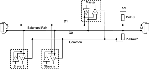
Fig. 6. Example: General RS-485 2-wire Topology
For connection and wiring diagrams, see Controller connections and Wiring diagrams in Technical reference data.
Cabling requirements
Field devices:
- The wires connected to the terminals have a cross-sectional area of at least 0.5 mm2.
- Twisted-pair cables, shielding recommended.
Modbus RTU or BACnet MSTP cable:
- Shielding twisted-pair. For example, Belden 3105A or Nomak 2x2x0.5+0.5.
- Max. bus length 1000 m.
- To avoid signal reflections, a 120 Ohm termination resistance must be added at the end of the main cable line.
Commissioning
Airflow control
The airflow rates for the Halton Max MOS are preset at the factory. If the airflow rates are not specified by the customer, the default factory settings are 0 for the minimum airflow rate and the nominal value (Vnom) for the maximum rate.
The nominal airflow rates in the following table are given with a pressure level of 110 Pa.
| Vnom [l/s) | ||||||||
| Width [mm] | 200 | 250 | 300 | 400 | 500 | 600 | 800 | |
| Height [mm] |
150 | 300 | 375 | 450 | 600 | 750 | 900 | – |
| 200 | 400 | 500 | 600 | 800 | 1000 | 1200 | 1600 | |
| 250 | – | 625 | 750 | 1000 | 1250 | 150 | 2000 | |
| 300 | – | – | 900 | 1200 | 1500 | 1800 | 2400 | |
| 400 | – | – | – | 1600 | 200 | 2400 | 3200 | |
Table 3. Vnom [l/s]
| Vnom [m3/h) | ||||||||
| Width [mm] | 200 | 250 | 300 | 400 | 500 | 600 | 800 | |
| Height [mm] |
150 | 1080 | 1350 | 1620 | 2160 | 2700 | 3240 | – |
| 200 | 1440 | 1800 | 2160 | 2880 | 3600 | 4320 | 5760 | |
| 250 | – | 2250 | 2700 | 3600 | 4500 | 5400 | 7200 | |
| 300 | – | – | 3240 | 4320 | 5400 | 6480 | 8640 | |
| 400 | – | – | – | 5760 | 7200 | 8640 | 11520 | |
Table 4. Vnom [m3/h]
The actual airflow rate is calculated as a function of different of differential pressure at the measurement probe, blade opening angle and the correct size k factor.
Maintenance
The product is easy to maintain. Normally, the electrical parts do not need maintenance. It is recommended to clean the internal parts of the product when cleaning the ductwork. Refer to the building maintenance program for the maintenance cycle.
Design examples
Office room design example
Description
Office environments place high demands on the ventilation and air quality. Halton Max MOS is perfect for air management in spaces where wide airflow ranges are needed. Silent ventilation system guarantees good working conditions. Minimum maintenance needs prevent creating disturbances in the daily activities.
Design data
- Office/meeting room area 14 m2
- Room minimum airflow 30 l/s
- Room maximum airflow 60 l/s
- Cooling load 500W, 36W/m2
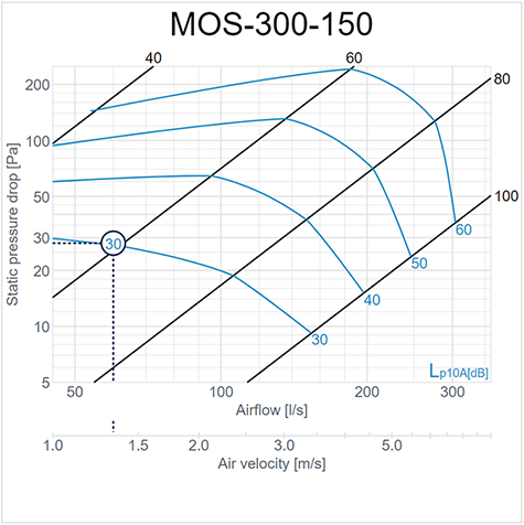
Fig. 7. Halton Max MOS performance
Ventilation design

Fig. 8. Halton Max MOS ventilation design
Components
- MOS with attenuator 600 length
- AGC-500-100
- PRL/F-500-100-200
- 2 x JDS/S-160
Schematic drawing
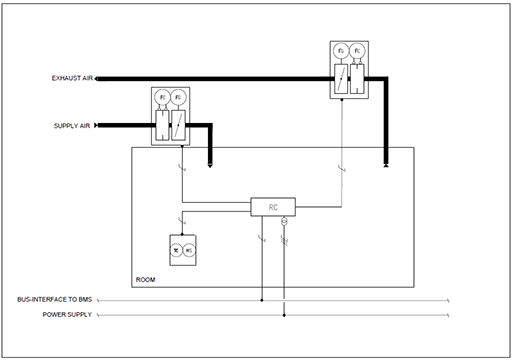
Fig. 9.Wiring example for Halton Max MOS with a master-slave configuration
In this example, the supply unit is controlling the exhaust unit.
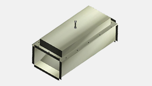
Accessories
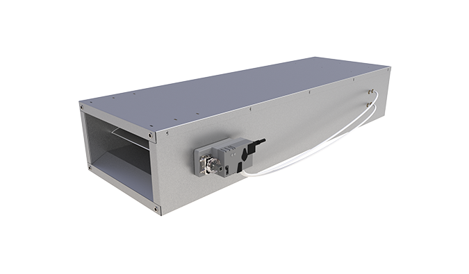
Reheat coils (RH)
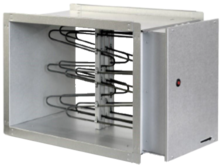
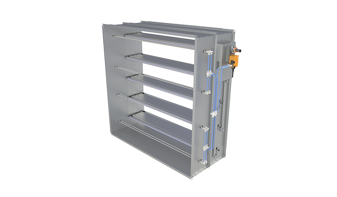
Fig. 10. Rectangular duct heater, electrical
Halton offers two models of reheater for ducts:
- Water heater/cooler coils are designed for cooling the ventilation air in a ventilation system. The reheater/cooler can also be used for heating or cooling individual rooms or zones.
- Electrical heaters, circular and rectangular, are designed to heat fresh air in a ventilation system.
For more information on the available reheat coils, see section Downloads.
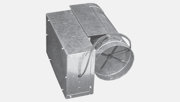
Sound attenuators (SA)
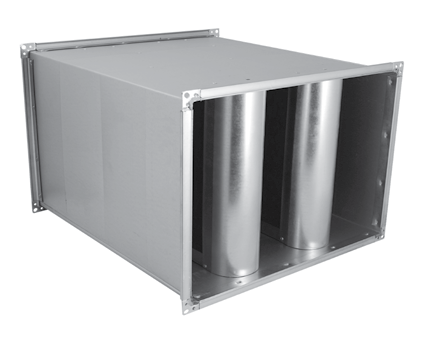
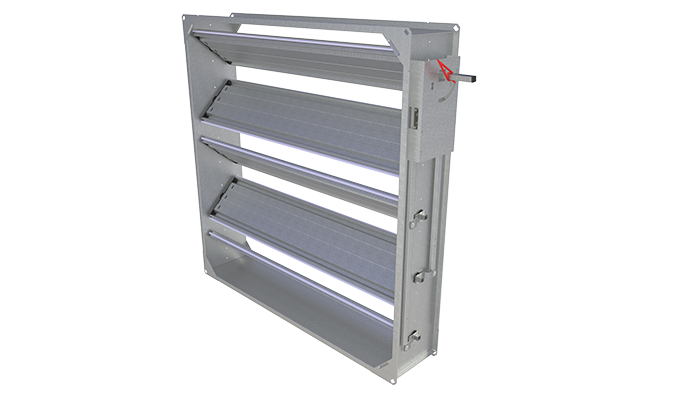
Fig. 11. Rectangular sound attenuator
Halton offers high-quality rectangular and circular sound attenuators for reducing noise levels in the duct.
For more information on the available sound attenuators, see section Downloads.
Downloads
ABD – Automated Balancing Damper for kitchen ventilation (CE)
product
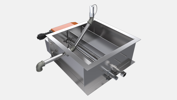
ABD – Automatic balancing damper for kitchen ventilation (ETL)
product
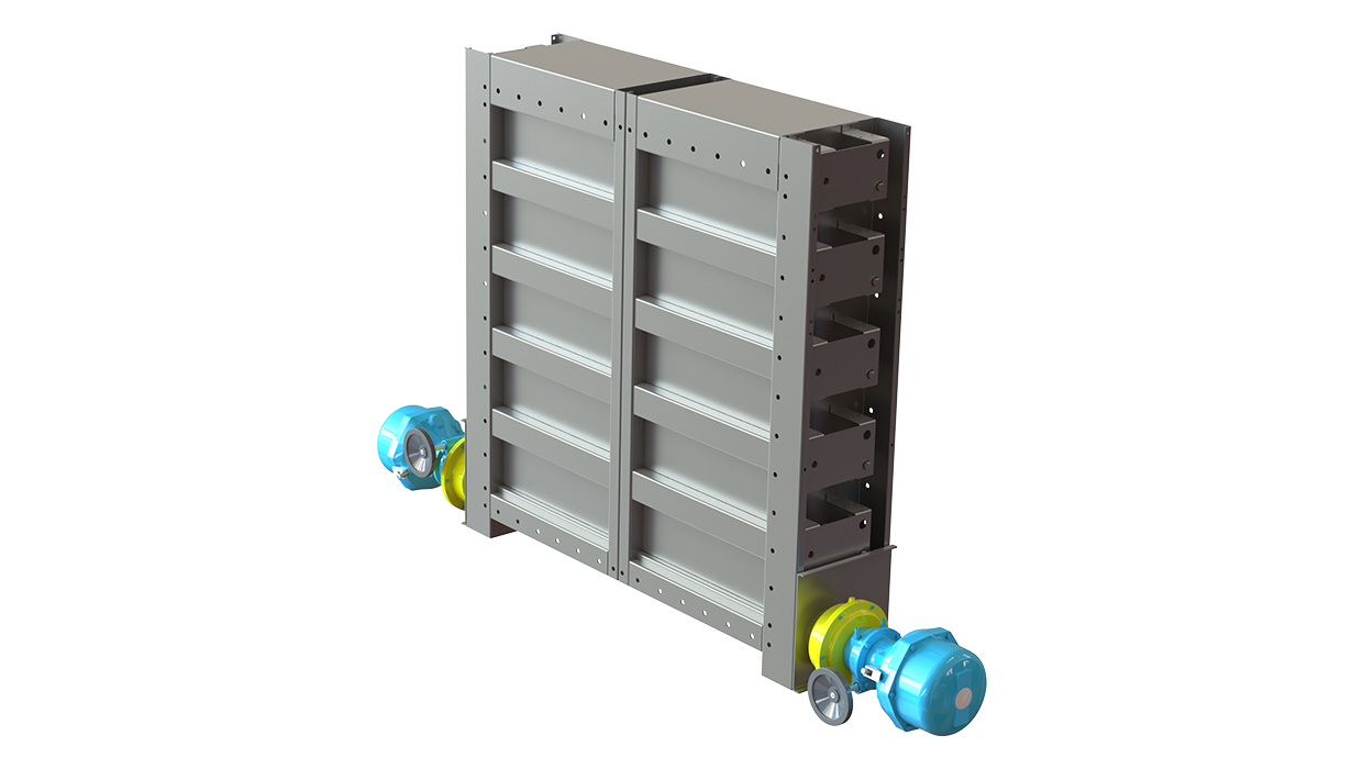
CID-01 – Zero leakage isolation damper
product
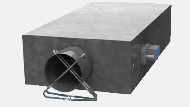
Halton BOX – Airflow management unit
product
Halton Max MDC – Zone control damper for Halton Workplace system
product
Halton Max MLC – Airflow management damper
product

Halton Max MOC – Airflow management damper (VAV)
product
Halton Max MSB – Slim airflow management damper
product

Halton Max MUC – Ultrasound airflow management damper
product
Halton PRA – Airflow management damper
product
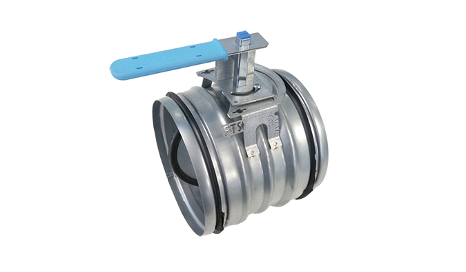
Halton PTS – Airflow management damper (single-blade)
product
Halton RMC – Airflow management damper (CAV)
product
Halton UKV – Airflow management damper (VAV)
product
Halton UTK – Multi-blade airflow management damper
product
Halton UTT – Multi-blade airflow management damper
product
Halton Vita VLR – Room airflow controller for Halton Vita Lab solutions
product
KBD – Exhaust hood balancing damper (ETL)
product
KVV-R – Kitchen ventilation rectangular VAV box
product
KVV-S – Kitchen ventilation square VAV box
product
MBD – Manual balancing dampers for kitchen ventilation (ETL)
product